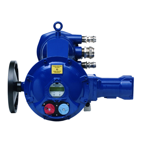
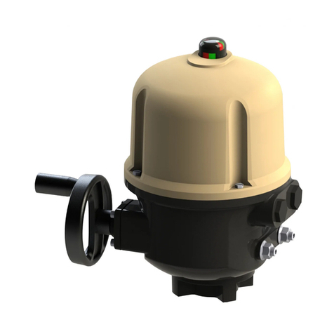
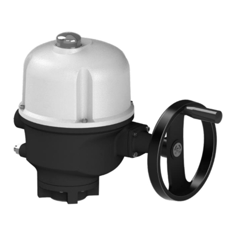
Bernard Controls AQL Series User guide

AQL Range
Start UpGuide SUG_17002 – Ind.A
Art : 5100465

TABLE OF LANGUAGES
1 English ---------------------------------------------------- 3
2 Français -------------------------------------------------- 3
3 Español -------------------------------------------------- 5
4 Italiana --------------------------------------------------- 7
5 Deutsch--------------------------------------------------- 7
2
49
37
25
13
3

TABLE OF CONTENTS
1SAFETY ---------------------------------------------------------- 3
2STORAGE AND MAINTENANCE -------------------------------- 3
Packaging & Storage
Maintenance
3ASSEMBLY ------------------------------------------------------- 4
Adapting the actuator to your valve input
Configuring position indicator for counter-clockwise closing
4MANUAL OVERRIDE---------------------------------------------5
5ELECTRICAL CONNECTION AND TESTS----------------------- 6
Checking after wiring
6TRAVEL LIMIT SETTINGS---------------------------------------7
Setting a single cam
Setting cams (AQ1L & AQ3L)
Setting cams and mechanical stops (AQ7L)
7PROPORTIONAL ANALOG COMMAND (OPTION) ----------- 10
Setting up positioner board
8TORQUE LIMITING DEVICE----------------------------------- 11
3
4
8
12
11
7
6
5
4

English
3
1SAFETY
This device complies with current applicable safety standards.
Installation, maintenance, and use of this unit require a skilled and
trained staff.
Please carefully read this whole document before mounting and
starting-up the actuator.
2STORAGE AND MAINTENANCE
Packaging & Storage
The AQL actuator is delivered in a cardboard box equivalent to the
size of the actuator and sits in a cardboard wedge.
It should be stored under a shelter, in a clean and dry place and
protected from wide temperature variations.
•Avoid placing the actuatordirectly on the floor.
•Check that cable entries' plugs are correctly tightened.
•Check that coverscrews are correctly tightened.
What to check after storage
1. Visually check the electrical equipment.
2. Operate the actuator manually.
What to check on pre-installed actuators
If you expect a long period between actuator mounting and electrical
wiring:
1. Visually check that cable entries and cover are tightly closed.
2. In case of outdoor installation, cover the unit with a plastic
protective film.
Maintenance
This actuator features lifetime lubrication and does not require any
specific maintenance. If it operates in a very wet atmosphere, you
are advised to check once a year that there is no condensation build-
up inside the unit.
4

English
4
3ASSEMBLY
After assembly, the actuator can operate in any position.
Adapting the actuator to your valve input
Actuator is supplied with a set of adapters to ensure the output fits
your valve shaft.
You only need to insert the accurate square adapter inside the socket.
Adapter can be oriented as parallel square or as diagonal square,
depending on your need.
Standard
On request
Standard
On request
Internal size in mm
Max. shaft length accepted 20mm
Internal size in mm
Max. shaft length accepted 25mm
AQ1L/AQ3L AQ7L
Adapters shapes (view from under the actuator)
However:
•Itis not recommendedto install actuatorwith coverdownwards
•Cable glandsmust not be orientedupwards
(loss of water tightness)
5

English
5
Configuring position indicator for counter-clockwise closing
As a standard, AQL actuator is configured to close clockwise. If the
actuator must close counter-clockwise, you can change orientation
of the position indicator cap.
Standard indicator orientation
for clockwise closing
Reverse indicator orientation
for counter-clockwise closing
How to change cap orientation
1. Disassemble the cover then the
cap.
2. Turn the cap 90°.
3. Reassemble the cap then the
cover.
4MANUAL OVERRIDE
You can operate the
actuator manually using the
driving square under the
actuator.
Output will turn in the
direction
opposite to the
rotation applied.
Square size is 10mm.
!
•Be careful not to damage actuator during manual operation.
Do not apply a torque higher than 6N
m to the square.
•Check indicator when driving actuator with manual override
to avoid reaching mechanical stops.
6

English
6
5ELECTRICAL CONNECTION AND TESTS
To perform electrical wiring, please refer to the wiringdiagram
supplied and follow theterminals' numbering.
!
Make sure not to wire AC supply on A, B, C terminals or DC supply
on 1, 2, 3 terminals, that will damage the board.
Checking after wiring
Once the actuator wiring is completed, the following points must be
checked:
1. Make sure that power supply voltage matches information on
the sticker on the side of the actuator.
2. Check that all connectors or cable glands are correctly
tightened.
3. Move the valve using manual override to an intermediate
position.
4. Electrically operate opening and closing travels and check that
the actuator rotates in the right direction and stops at the
desired position.
If any fault is detected at this stage, please check all wiring.
Never use a powered rotary equipment on manual override to
operate the actuator.
7

English
7
6TRAVEL LIMIT SETTINGS
The actuator is factory-set for a 90°travel.
It features 2 devices to limit the travel:
•Cams trigger switches toswitch off power at an end position or
to signal a position.
•Mechanical stops mechanically block rotation toprotect the valve
in case ofover-travel. They must not beused as travel limits.
Setting a single cam
The cam rotates as the
output shaft and triggers a
switch by pushing on its
lever.
Cams orientation are factory
pre-set, yet you can still re-
adjust them upon the
installation if necessary.
Rep. Function Status before installation
1
Clockwise travel limit
Pre-wired, cam pre-set
2
Counter-clockwise travel limit
Pre-wired, cam pre-set
3
Clockwise signalling
To wire, to set
4
Counter-clockwise signalling
To wire, to set
How to adjust asingle cam
At the desired position of the actuator output:
1) Turn the setting screw of
the corresponding cam
with a flat-head
or a
Phillips-head screwdriver.
The cam disk is then turning.
2) Set the cam disk until you
hear a click from the
switch. It
indicates the
triggering of the switch.
Make sure the cams contact the switch according to their proper
direction of travel, otherwise you could damage the switch.
8

English
8
Travel limit cams and signalling cams
On AQL actuator, you have 4 cams
with 2different functions:
•Travel limit cams cut motor
power supply when they
trigger the switches
corresponding to an end
position.
•Signalling cams are not wired
by default. You can use them
to indicate when the
actuator gets close to an end
position.
Signalling cams must be set to reach their corresponding switch
before the travel limit cams do.
If the actuator is supplied mounted on a valve, following
settings should have been performed by the valve supplier.
Setting cams (AQ1L & AQ3L)
AQ1L & AQ3L have fixed mechanical stops. Travel limit settings are
done by cams only.
How to adjust cams for both directions
1. Drive the actuator to clockwise travel limit position.
2. Set the cam corresponding to clockwise travel limit switch.
If the clockwise signalling switch is wired:
3. Drive the output slightly in the counter-clockwise direction
using manual override.
4. Set the cam corresponding to clockwise signallingswitch.
5. Drive the actuator to the counter-clockwise travel limit
position.
6. Redo settings steps 2 to 4 for counter-clockwise direction.
9

English
9
Setting cams and mechanical stops (AQ7L)
AQ7L has both mechanical stops and cams that can be set.
Setting travel limits
The mechanical stops limit
the actuator travel.
Fine adjustment of the stop
screws position is possible
within a limit of ±2°
maximum. These screws are
located inthe lower section
of the actuator.
The actuator stops on open
or closed position when the
travel limit switch is
tripped.
How to adjust cams and mechanical stops for both directions
One turn of the adjustment screw = 4° angle variation at the
actuator output.
1. Untighten the nut corresponding to clockwise mechanical
stop and turn stop screw 2 turns back.
2. Drive the actuator to clockwise travel limit position.
3. Get the clockwise stop screw in contact with output sleeve
then turn it back of 1.5 turns.
4. Retighten nut to keep position of mechanical stop.
5. Set the cam corresponding to clockwise travel limit switch.
If the clockwise signalling switch is wired:
6. Drive the output slightly in the counter-clockwise direction
using manual override.
7. Set the cam corresponding to clockwise signalling switch.
8. Untighten the nut corresponding to counter-clockwise
mechanical stop and turn stop screw 2 turns back.
9. Drive the actuator to the counter-clockwise travel limit
position.
10. Redo settings steps 3 to 7 for counter-clockwise direction.
10

English
10
7 PROPORTIONAL ANALOG COMMAND (OPTION)
The proportional analog
command allows to drive
the valve to intermediate
positions.
Board is factory pre-set.
Perform the electrical
wiring according to the
wiring diagram of the
actuator.
Setting up positioner board
Take care that the board is supplied during setting process.
The actuator is delivered with the proportional analog command
already installed, and the settings have already been done at
our factory.
Only go through the setup procedure below if you had to adjust the
mechanical end stops positions. Board setup is fully automatic.
How to run the board setup
1. Press for 5 seconds on the SW1 push button located on the
board.
The yellow LED is blinking while the setup is in progress and
is remaining lit when the setting is completed.
2. Control the setup by performing some clockwise and counter-
clockwise operations.
11

English
11
If the LED continues to blink after the automatic process, it is
indicating the following errors:
Times
blinking
2
3
4
5
Configuration
was not
correctly
loaded
4/20 mA signal
is lost
Actuator is
blocked
during travel
•Rotation direction is
wrong
•Actuator got to a
position out of
travel limits
•Actuator is pumping
How to set closing direction and fallback position
You can use SW2 dip switches to set closing direction (dip switch 1)
and fallback position (dip switches 2 & 3)in case signal is lost.
This setting must be done with power off.
Closing
direction
1
Fallback
position
3
ON
OFF
ON
Clockwise
2
ON
Stayput Closed
OFF
Counter-
clockwise
OFF
Open Stayput
8TORQUE LIMITING DEVICE
In case of excessive torque on the actuator, a torque limitation
system shuts down actuator.
A LED behind switch board is lighting up when this protection is ON.
How to re-start the actuator if torque limiter went off
1. Switch power supply off.
2. Check if the issue comes from valve (stiff point or jamming)
or mechanical stops (over-travel or wrong mechanical stop
settings).
3. Fix the issue.
4. Switch power supply on and electrically operate actuator in
both directions.
LED remainslita few seconds after power supply is switched off.
Wait those few seconds before switching power supply on again and
operating actuator.
12

SOMMAIRE
1SÉCURITÉ-------------------------------------------------------- 3
2STOCKAGE ET ENTRETIEN-------------------------------------3
Emballage et stockage
Entretien
3ASSEMBLAGE ---------------------------------------------------- 4
Adapter le servomoteur à votre entrée de vanne
Configuration de l'indicateur de position pour la fermeture
dans le sens anti-horaire
4COMMANDE MANUELLE DE SECOURS-------------------------5
5CONNEXION ÉLECTRIQUE ET TESTS-------------------------- 6
Vérification après câblage
6RÉGLAGES DES FINS DE COURSE ----------------------------- 7
Réglage d'une came
Régler les cames (AQ1L & AQ3L)
Régler les cames et butées mécaniques (AQ7L)
7COMMANDE PROPORTIONNELLE ANALOGIQUE (OPTION) 11
Régler la carte de positionnement
8LIMITEUR DE COUPLE---------------------------------------- 13
14
13
24
22
18
17
16
15
14

Français
3
1SÉCURITÉ
Cet appareil est conforme aux normes de sécurité applicables.
L'installation, l'entretien et l'utilisation de cet appareil nécessitent
un personnel qualifié et formé.
Veuillez lire attentivement ce document avant de monter et
démarrer l'actionneur.
2STOCKAGE ET ENTRETIEN
Emballage et stockage
L'actionneur AQL est livré dans une boîte en carton équivalente à la
taille de l'actionneur et repose sur une cale en carton.
Il doit être stocké sous abri, dans un endroit propre et sec et protégé
des grandes variations de température.
•Évitez de placer l'actionneur directement au sol.
•Vérifiez que les bouchons d'entrée de câble sont correctement
serrés.
•Vérifiez que les vis du couvercle sont correctement serrées.
Que vérifier après le stockage
1. Inspectez visuellement la partie électrique.
2. Manoeuvrez manuellement l'actionneur.
Que vérifier sur les servomoteurs pré-installés
Si vous prévoyez une longue attente entre le montage de l'actionneur
et le câblage électrique:
1. Vérifiez que les entrées de câble et le couvercle sont
fermement serrés.
2. En cas d'installation en extérieur, protégez l'appareil avec un
film plastique.
Entretien
Ce servomoteur est lubrifié à vie et ne nécessite pas de maintenance
spécifique. S'il fonctionne dans une atmosphère très humide, il est
conseillé de vérifier une fois par an qu'il n'y a pas de condensation à
l'intérieur.
14

Français
4
3ASSEMBLAGE
Après assemblage, l'actionneur peut fonctionner dans n'importe
quelle position.
Adapter le servomoteur à votre entrée de vanne
Le servomoteur est fourni avec un ensemble d'adaptateurs pour
assurer que la sortie s'adapte à votre tige de vanne.
Il suffit d'insérer l'adaptateur carré correspondant dans la douille.
L'adaptateur peut être orienté dans l'axe ou hors axe, selon votre
besoin.
Standard
Sur demande
Standard
Sur demande
Mesure interne en mm
Longueur maximale de tige 20mm
Mesure interne en mm
Longueur maximale de tige 25mm
AQ1L/AQ3L AQ7L
Formes des adaptateurs (vue de sous l'actionneur)
Cependant :
•Il est déconseillé d'installer l'actionneur avec le couvercle vers
le bas
•
Les presse-étoupes ne doivent pas être orientés vers le haut
(perte d'étanchéité)
15

Français
5
Configuration de l'indicateur de position pour la fermeture
dans le sens anti-horaire
En standard, l'actionneur AQL est configuré pour se fermer dans le
sens horaire. Si l'actionneur doit se fermer dans le sens anti-horaire,
vous pouvez modifier l'orientation du hublot de l'indicateur de
position.
Orientation standard de
l'indicateur
Pour la fermeture dansle sens
horaire
Orientation inversée de
l'indicateur
Pour la fermeture dansle sens
anti-horaire
Changer l'orientation du hublot
1. Démontez le couvercle puis le
hublot.
2. Tournez le hublot de 90°.
3. Remontez le hublot puis le
couvercle.
4COMMANDE MANUELLE DE
SECOURS
Vous pouvez actionner le
servomoteur manuellement à
l'aide du carré situé en
dessous.
La sortie tourne dans le sens
opposé à la rotation
appliquée.
La taille du carré est de 10
mm.
16

Français
6
!
•Veillez à ne pas endommager le servomoteur lors d'une
manœuvre manuelle.
Ne pas appliquer au carré un couple supérieur à 6 N.m.
•Surveillez l'indicateur lors de la manœuvre
manuelle pour
éviter d'atteindre les butées mécaniques.
5CONNEXION ÉLECTRIQUE ET TESTS
Pour effectuer le câblage électrique, reportez-vous au schéma de
câblage fourni et suivez la numérotation des bornes.
!
Veillez à ne pas brancher l'alimentation en CA sur les bornes A,
B, C ou l'alimentation en CC sur les bornes 1, 2, 3, ce qui
endommagerait la carte électronique.
Vérification après câblage
Une fois que le câblage du servomoteur est terminé, les points
suivants doivent être vérifiés:
1. Assurez-vous que la tension d'alimentation correspond à celle
indiquée sur l'autocollant placé sur le côté de l'actionneur.
2. Vérifiez que tous les connecteurs ou les presse-étoupes sont
correctement serrés.
3. Amenez la vanne à une position intermédiaire à l'aide de la
commande manuelle.
4. Effectuez électriquement une ouverture et une fermeture.
Vérifiez que le servomoteur tourne dans le bon sens, et
s'arrête à la position désirée.
N'utilisez jamais un appareil tournant motorisé sur la commande
manuelle pour entraîner l'actionneur.
Si une erreur est détectée à cette étape, vérifiez tout le câblage.
17

Français
7
6RÉGLAGES DES FINS DE COURSE
Le servomoteur est réglé en usine pour une course de 90°.
Il comporte 2 dispositifs pour limiter la course :
•Les cames déclenchent des contacts pour couper l'alimentation
en fin de course ou pour signaler une position.
•Les butées mécaniques bloquent mécaniquement la rotation pour
protéger la vanne en cas de surcourse.
Ils ne doivent pas être utilisés comme fins de course.
Réglage d'une came
La came tourne comme
l’arbre de sortie et
déclenche un contact en
appuyant sur son levier.
L'orientation des cames est
pré-réglée en usine, mais
vous pouvez toujours
l'ajuster lors de l’installation
si nécessaire.
Rep. Fonction État avant l’installation
1
Fin de course dans le sens horaire
Précâblé, came pré-réglée
2
Fin de course dans le sens anti-horaire
Précâblé, came pré-réglée
3
Signalisation dans le sens horaire
A câbler, à régler
4
Signalisation dans le sens anti-horaire
A câbler, à régler
18

Français
8
Comment régler une came
A la position de la sortie du vérin souhaitée :
1) Tournez la vis de réglage de
la came correspondante
avec un tournevis à bout
plat ou cruciforme.
Le disque de came tourne.
2)
Réglez le disque de came
jusqu'à ce que vous
entendiez le
contact faire
un clic. Cela indique le
déclenchement du contact.
Cames de fin de course et cames de signalisation
Sur le servomoteur, vous disposez
de 4 cames avec 2 fonctions
différentes :
•Les cames de fin de course
coupent l'alimentation du
moteur
quandelles
déclenchent
le
contact
correspondant à une fin de
course.
•Les cames de signalisation
ne sont par défaut pas
câblées. Vous pouvez les
utiliser pour signaler
l'approche de la fin de
course.
Les cames de signalisation doivent être réglées pour atteindre leur
contact correspondant avant les cames de fin de course.
Si l’appareil est livré monté sur une vanne, les réglages qui
suivent ont normalement déjà été effectués par le
fournisseur de vanne.
Assurez-vous que les cames atteignent le contact dans le sens de
leur actionnement, sinon vous pourriez l’endommager.
19
Signalisation
Fin de course

Français
9
Régler les cames (AQ1L & AQ3L)
AQ1L & AQ3L ont des butées mécaniques fixes. Le réglage des fins
de course se font avec les cames.
Comment régler les cames pour les deux directions
1. Amenez le servomoteur en fin de course dans le sens horaire.
2. Réglez la came correspondant au contact de fin de course du
sens horaire.
Si le contact de signalisation de sens horaire est câblé :
3. Faites légèrement tourner la sortie dans le sens anti-horaire
avec la commande manuelle.
4. Réglez la came correspondant au contact de signalisation du
sens horaire.
5. Amenez le servomoteur en fin de course dans le sens anti-
horaire.
6. Répétez les étapes de réglage 2 à 4 pour le sens anti-horaire.
Régler les cames et butées mécaniques (AQ7L)
AQ7L possède des butées mécaniques et des cames réglables.
Régler les fins de course
Les butées mécaniques
limitent la course du
servomoteur.
Le réglage de la vis de butée
est possible dans la limite
de ±2°. Ces vis sont situées
en partie basse du
servomoteur.
L’actionneur s’arrête en
position ouverte ou fermée
lorsque le contact de fin de
course est déclenché.
20
1 tour de vis
vers la droite
1 tour de vis
vers la gauche
This manual suits for next models
3
Table of contents
Languages:
Other Bernard Controls Switch manuals
Popular Switch manuals by other brands

Pilz
Pilz PSEN ma1.4n-50 operating manual

Cisco
Cisco Nexus 7000 Series Hardware installation and reference guide

ZyXEL Communications
ZyXEL Communications IES-1248-71 user guide

TRENDnet
TRENDnet TK-207K - KVM Switch - USB Guía del usuario
Contemporary Controls
Contemporary Controls CTRLink EISK8-GT/H installation guide

Cisco
Cisco Catalyst 6840 Series Troubleshooting
