Bernee BN-5606XCAR User manual
Bernee®
1/ 13
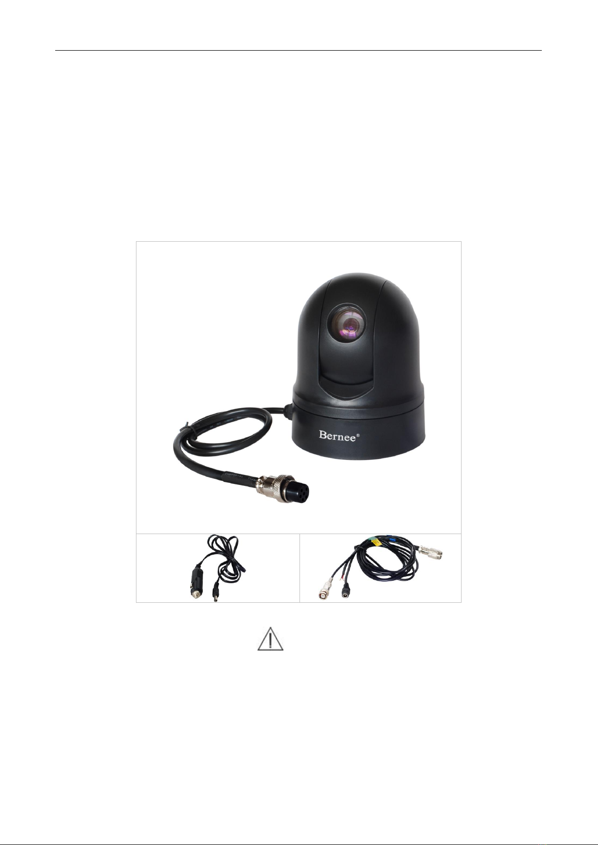
Vehicle Speed Dome User Manual
BN-5606XCAR
DC 12V
Berneeproduction
----------------------------------------------------------------------------------------------------------
Please read this User Manual carefully to ensure that you can use the device correctly and safely.

Bernee®
2/ 13
Index
MAIN CAUTIONS..................................................................................................................................................... 3
PRECAUTIONS ....................................................................................................................................................... 3
1. PREFACE......................................................................................................................................................... 4
2. FEATURES....................................................................................................................................................... 4
3. FUNCTION INTRODUCTION ......................................................................................................................... 4
4. INSTALLATION AND CABLE CONNECTION METHOD............................................................................. 6
4.1 DIMENSION......................................................................................................................................................... 6
4.2 BOTTOM PLATE STRUCTURE.............................................................................................................................. 6
4.3 6-PIN AVIATION PLUG &6-PIN CABLE ................................................................................................................. 6
4.4 VIDEO,POWER,CONTROL LINE.......................................................................................................................... 7
4.5 CABLE CONNECTING.......................................................................................................................................... 7
4.6 TWO METHODS FOR DOME INSTALLATION.......................................................................................................... 7
5. DOME SWITCHER SETTING......................................................................................................................... 7
5.1 VEHICLE DOME ADDRESS SETTING .................................................................................................................... 8
5.2 COMMUNICATION PROTOCOL &BAUD RATE SETTING...................................................................................... 10
5.2.1 Communication protocol setting ......................................................................................................... 10
5.2.2 Baud rate setting................................................................................................................................... 10
6. BASIC CONTROL FOR DOME.....................................................................................................................11
6.1 POWER CONNECTION SELF-TEST .................................................................................................................... 11
6.2 PRESET SETTING.............................................................................................................................................. 11
6.3 CALL PRESET ................................................................................................................................................... 11
7. INSTALLATION...............................................................................................................................................12
8. CLEANING ......................................................................................................................................................12
9. SPECIFICATIONS...........................................................................................................................................12
APPENDIX: SIMPLE FAULTS SOLVING.............................................................................................................13

Bernee®
3/ 13
Main Cautions
Please read this manual carefully before installing
Comply with all caution items on device & manual
Comply with all indicated operations as well as manual
Use components recommended by seller avoiding fault
This product should use specified power supply & voltage. If practical power supply & voltage is
unknown, please ask for seller.
Do not disassemble body but contact to seller
With body cleaning do not use strong or grinding detergent.
Use a dry, soft cloth to clean the camera shell when it is dirty. If very dirty, please use neutral
detergent rather than strong detergent in order to taken not to scratch the dome when wiping it. Then
use dry cloth wiping rest detergent.
Happen the following faults, please contact with dealer:
- Power supply and control line destroyed
- Body fell down or shell destroyed
- Device performance works abnormal
- Yet abnormally work after operation according to instruction
With component replacement, please use those components offered by dealer or performed
equally.
Precautions
Do not direct to sunlight with camera
Do not aim to shining objects with camera. Never aim to sunlight or other strong light objects no
matter during operating or not.
Do not long-time aim to strong light or expose in light source
If equivalent light forms facula, part of image will fade caused by CCD filter worsening under camera
face changing.
This product standard voltage is DC 12V
For seldom vehicle power sockets (lighter socket) are DC 24V and improper voltage will
damage camera greatly, please ensure power socket (lighter socket) voltage is DC 12V.

Bernee®
4/ 13
1. Preface
Vehicle speed dome is our advanced monitoring product with optical, mechanical and electronic
integration. It includes dynamic structure, precision actuator, CCD camera, digital decoder, image
processing unit and controller. Machinery structure designs simply and is precise. High precision &
reliability; smart operating, high speed, stable start & stop, easy control; multi-object presetting,
remember and auto tour; random position, true Omni-bearing & non-blind point monitoring; auto adjust
object distance and size to suit ambient brightness, high cost-performance, long-term stable running.
2. Features
Vehicle environmental designment, anti-shake, waterproof, IP66 protection grade
Horizontal 360°continuous running, max speed 100°/s.
Vertical -15°to 90°rotation from which begin to auto flip 180°and continuous monitoring.
64 customized presets
Auto tour function: 0~54 presets orderly switch
Set max running speed and proportional speed-down, fast call preset positions and manually
control precision tracking
RS485-485 bus-control
Built-in memory to store the setting data, which can not be lost after power off
Compatible with various protocols with adjustable baud rate (Pelco-P /Pelco-D/ Kalatel/
Samsun/ AD)
High-strength plastic shell with light weight
In installing, suck dome onto vehicle roof by owned magnet, or use three M5 screws mounting
dome onto vehicle roof
DC 12V power supply
3. Function Introduction
The following will introduce main functions of integrated speed dome, as well as various functions
operation (no operation details).
Set address code, baud rate and control protocol
Each command matches with only one camera address code, baud rate and control protocol, single
camera only reacts to commands matched to own address code, baud rate and control protocol.
Motion control
Customer can use keyboard controller to manage camera rotation, tracking motion object or motion
sight; besides can change view-angle or image size with adjusting focal length. In auto focus state, as
lens moving, camera will according to sight change adjust automatically, getting clear image.
Focal length / running-speed auto matching
In manual state, for long focal length, slight moving of controller will cause so great changes on
image as to data loss. Based on humanity designment, dome according to focal length can auto adjust
horizontal / vertical speed, so as to make manual tracking easier.

Bernee®
5/ 13
Auto flip
If lens is pulled until up to top (vertical 90°), it will auto horizontally turning 180°and then flip
downward, which can directly watch backside sight. This process ensures vertical 180°continuous
monitoring.
Set and call preset position
Preset function means that in present state, pan/tilt angle and focal length data stores into memory
in order to call and place pan/tilt with camera to specified position. Customer can store and call presets
with controller o infrared controller easily. This function supports 64 presets.
Lens control
- Focal length control
Customer can adjust focal length with controller or matrix so as to get full shot or close-up shot.
- Focus control
In auto focusing & zooming state, camera will focus on picture center to keep picture clear; in
special condition, customer can manually focus to get needed effect. Manual focus restores to auto
focus only needs shake joystick.
- Aperture control
Customer can manually adjust aperture size with controller to get needed picture
brightness. It is also operable to restore auto adjustment by calling a preset position.
Auto backlight compensation
When backlight compensation opens, camera can auto compensate brightness for dark sight
among strong light background. Adjusting background lighting prevents such a brightness mass on
careen caused by background brightness as to can not distinguish dark object, so that you can get clear
image.
ATW (auto tracking white)
Automatically adjust according to ambient light changes to reveal true color.
Auto tour
We can beforehand set presets for tour and put them into an ordered queue, a calling command
required only for that all points (domes) operate circularly based on certain interval.
Zone scanning
Only an outer command or power connection is required for that all domes circularly & horizontally
scan within certain scope (55°~63°or specified angle) with a speed.
Table of contents
Other Bernee Security Camera manuals


