Berthoud VEGA 120 User manual

1
Duster VEGA 120
377.563-A ENGLISH
to be read attentively
and kept for further reference
© BERTHOUD Agricole 06/2008

2
See pages
- GENERAL AND SAFETY
.Warning----------------------------------------------------------------------- 4
.Technical specifications -------------------------------------------------- 5
.Dimensions and weight --------------------------------------------------- 5
.Position of the safety stickers and the descriptive plate----------- 6
.Meaning of the safety stickers------------------------------------------- 7/8
. Acceptable use of the duster -------------------------------------------- 9
.General safety instructions----------------------------------------------- 10
. Hitching ----------------------------------------------------------------------- 10
.Hydraulic circuit ------------------------------------------------------------- 10
.Maintenance ----------------------------------------------------------------- 10
- STARTING-UP THE DUSTER
.Hitching the duster to the tractor ---------------------------------------- 12
.Filling the hopper ----------------------------------------------------------- 12
-OPERATION
.Outputadjustment----------------------------------------------------------- 14
.Selecting the produt output direction----------------------------------- 14
.Clogging in the product feed venturi nozzle -------------------------- 15
.Flowbalancing -------------------------------------------------------------- 15
.Torquelimiter----------------------------------------------------------------- 15
- DETERMINATION OF THE FLOW RATE
.Table of flow rates ---------------------------------------------------------- 18
- MAINTENANCE
.Drive maintenance --------------------------------------------------------- 20
.Maintenance during periods of use ------------------------------------ 20
.Maintenance when not in use-------------------------------------------- 20
contents

3
GENERAL
AND
SAFETY

4
- Successful treatment depends on correct operation of your duster.
- Correct operation depends on precise calibration of the equipment, and
this requires careful checking.
- When this checking has been undertaken, the duster must be
commissioned correctly, this also being necessary for correct spraying
and operation.
- Finally, to be certain that your duster can give you the performance you
expect, for a long time, make sure that you undertake the maintenance
operations required.
CHECKING, STARTING-UP,
OPERATION, MAINTENANCE
are therefore essential operations, and you have every reason to carefully
read the details in this booklet.
"This duster has been manufactered using materials which withstand most
plantprotection chemicalscurrently availableon themarket. Nevertheless,
BERTHOUD cannot assume responsibility for any damage resulting from
anincompatibilittyof the crop protection chemicals or productmixtures with
theplastic materials (polyethylene, polyvinylchloride, polypropylene, Vitton,
nitrile polyamide,ABS)."
CLEANING THE DUSTER
- Only BERTHOUD is qualified to assist you concerning the maintenance of
the duster and the choice of cleaning products.
- Care should be taken with products containing solvents. Such products
may attack and damage plastic and rubber elements and paint. Berthoud
cannotbe held responsibleincases where inappropriatecleaners are used.
We recommend the ALL CLEAR cleaner.
IMPORTANT
- According to the terms of article R 149 of the Highway Code, any
towed agricultural machine with a GVWR over 1.5 tonnes must be
fitted with a braking mechanism for driving on the public highway.
Because of our policy of constant product improvement,
we reserve the right to modify product specifications or design without prior notice.
WARNING

5
Duster VEGA 120
- Fan speed : 3,490 rpm
- Air flow per outlet : 880 m3/h
- Absorbed power : 4.5HP
- CHASSIS
- Steel profile and plate.
- HOPPER
- Sheet plate.
- Capacity : 120 litres.
- Wide filling orifice.
-Discharge hole.
- MECHANISM
- Speed-increasing gear to V-belts.
- MIXER
- Finger agitator to prevent bridging,
fitted with a torque limiter.
- FEEDING
- By endless screw.
- This system ensures the powder
flowsevenly.
- Length : 1.040 m.
-Width : 0.760 m.
- Height : 0.980 m.
- Weight : 93 kg.
- As the powder does not go through the rotor, micro-granules can be used.
-FAN
- Aluminium.
- Rotationspeed: 3,490rpm.
- ADJUSTMENT
- 8-positionnotched lever.
- Flow of 4 to 88 kg/ha.
- DISTRIBUTION
- Throughdoubleswivelling blades.
- Powder equalising device to ensure perfectly even left-right balance.
- MAINTENANCE
- All greasers located on the right-hand side with grease ducts.
TECHNICAL SPECIFICATIONS
DIMENSIONS AND WEIGHT

6
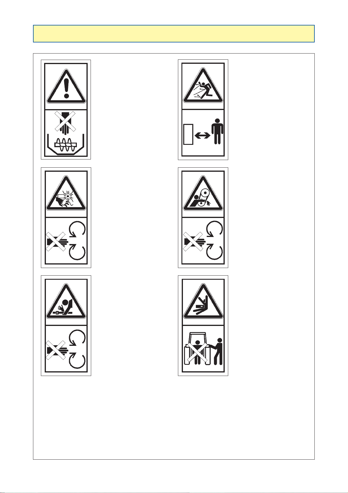
It is very important to keep the safety stickers in
location and in good condition as they draw your
attention to possible dangers and refer to the
operator's manual.
See the following pages and check their location
on the duster.
- Duster VEGA 120 -
417.590
418.630417.572 417.579
On the hood in front of the duster
T/min
R/min
U/min
G/min
540
200
417.588
On the hood
in front of the duster
417.583
In front of the
duster
POSITION OF THE SAFETY STICKERS

7
GENERIC WARNING
SYMBOL
READ THE OPERATING
MANUAL BEFORE
ANY OPERATION
SWITCH OFF THE
ENGINE AND REMOVE
THE IGNITION KEY
BEFORE UNDER-TAKING
WITH ANY INSPECTION,
MAINTENANCE OR
REPAIR OPERATION
RISK OFASPHYXIA
DO NOT ENTER
IN THE TANK
RISK OF ELECTRIC
SHOCKAND
ELECTROCUTION
HAND
PROTECTION
OBLIGATORY
FOOT
PROTECTION
OBLIGATORY
AIR PASSAGE
PROTECTION
OBLIGATORY
EYE
PROTECTION
OBLIGATORY
ROTATING SPEED OF
540 REVOLUTIONS
PER MINUTE
RECOMMENDED
HAND PROTECTION
OBLIGATORY FILL WITH CLEAR
WATER
OBLIGATIONTO WASH
YOURHANDS
T/min
R/min
U/min
G/min
540
MEANING OF THE SAFETY STICKERS
8
KEEP HANDS AWAY
FROM THE SCREW
WHILE THE TRACTOR
POWER TAKE-OFF
SHAFT IS CONNECTED
AND THE ENGINE IS
RUNNING
RISK OF INJURY
KEEP HANDS AWAY
FROM VENTILATION
FAN WHILE THE
TRACTOR POWER
TAKE-OFF SHAFT IS
ENGAGED AND THE
ENGINE IS RUNNING
RISK OF SNATCHING
DO NOT OPEN OR
REMOVE THE
PROTECTIVE COVERS
WHILE THE TRACTOR
POWER TAKE-OFF
SHAFT IS ENGAGED
AND THE ENGINE IS
RUNNING
RISK OF PROJECTION
STAY ATA SAFE
DISTANCE FROM
THE SPRAYER
RISK OF CRUSHING
KEEPA SAFE DISTANCE
FROM THE SPRAYER
RISK OF SNATCHING
DO NOT OPEN OR
REMOVE THE
PROTECTIVE GUARDS
WHILE THE TRACTOR
POWER TAKE-OFF
SHAFT IS ENGAGED
AND THE ENGINE IS
RUNNING
GENERIC WARNING
SYMBOL
MEANING OF THE SAFETY STICKERS

9
- Do not use your duster out of its function:
- sprayingcrop protection chemicals, spraying of plant protective products.
- Inthe event of any damage related tothe useof the duster outside theframework ofthe applications specified
by the manufacturer, the latter shall not be liable.
- Any extrapolation of the sprayer's original intended use shall be at the user's risk.
- Acceptable use of the duster also implies:
- compliance with the operating, servicing and maintenance instructions laid down by the manufacturer,
- the exclusive use of original spare parts, equipment and accessories or those recommended by the
manufacturer.
- The duster must only be used, serviced and repaired by trained people, familiar with its characteristics and
methods of use.
These people must also be aware of the dangers they may be exposed to.
- The user must comply strictly with existing regulations as regards:
- accident prevention,
- safety at work (Labour Code),
- travellingon the public highway(Highway Code).
- He must strictly observe the warnings affixed on the duster.
- Any change to the duster done by the user himself or any other person, without the manufacturer's prior
written agreement, shall mean that the latter is not liable for any damages which may result.
ACCEPTABLE USE OF THE DUSTER

10
GENERAL SAFETY INSTRUCTIONS
- This duster should be used by a fully trained operator in spray techniques.
- Do not allow anyone to enter the duster's working radius.
- When using hydraulic, electrical or other controls, first ensure that there is no-one within range of the spray.
- The only workpost is the tractor's cab when the duster is in operation.
- In addition to the instructions contained in this manual, comply with the legislation relating to safety and
accident prevention regulations.
- The stickers on the duster indicate safety measures to be complied with to prevent accidents.
- The user must train himself in the operation of this duster before doing any work.
- Protect yourself from spray drift during spraying.
- No passengers should be carried on the duster.
- Take care when hitching or unhitching the duster.
- Before hitching the duster, make sure that there is sufficient ballast on the tractor's front axle.
- All the remote controls must be placed so that they cannot cause a dangerous situation.
- Before doing anything on the duster, disconnect the power take-off, switch off the engine, remove the ignition
key and wait until the sprayer has stopped completely.
- Make sure that all the safety covers are in place.
- Carry out the adjustments and a water spray test before preparing the spray mixture.
- Dispose of chemical cans in accordance with the instructions given by the manufacturer.
HITCHING
- Beware of crush risks in the 3-point lifting area.
- Disconnect the power take-off, switch off the engine and remove the tractor's ignition key while the duster's
drive shafts are being connected.
- Use only EC-approved drive shafts. Fit them and service them in accordance with their manufacturer's
instructions. Replace their protectors as soon as they are damaged.
- The protective covers must always be in place and properly secured.
- Rest the drive shafts on their supports as soon as they are disconnected.
HYDRAULIC CIRCUIT
- Before connecting a hose to the tractor’s hydraulic system, make sure that the tractor and sprayer-side
circuits are not pressurized.
- Check that the hydraulic hoses are in good condition and replace them if they are damaged.
MAINTENANCE
- For all maintenance work, the PTO has to be disconnected, the tractor engine must be switched off, the
ignition key removed.
IMPORTANT: Formanually or hydraulically operated equipmentwith lifting, folding or extension gear,
etc. and prior to all maintenance work, even of minor importance, mechanical parts must be at the
limit of their travel, jack pressure off, arms on their supports and sliding or swinging frames locked
into position.
- Only use recommended spare parts by BERTHOUD.

11
STARTING-UP
THE DUSTER
12
- Attach the tractor’s lifting arms to the two pins on the drawbar.
- Mountthe cardan drive shaft.If necessary, cut the tube tothe required length and removeany burrs. Lubricate
thetubes.
- Attach the top link to the duster mounting pin.
- Lift the device to the required height using the lifting arms so that the drive shaft angle is as flat as possible.
The drive shaft angle must not be greater than 15° in relation to the PTO.
- PTO operating speed: 540 rpm.
- Rest the bag of powder on the rear edge of the
hopper.
While pouring it in, check that there are no foreign
bodies (pieces of bag or other) in the powder.
- Before filling the hopper, check that the opening
lever (1) is in the closed position, i.e. with the lever
in the top position, notch No. 1 (figure 1, ref. c1).
- Check that the gate (4) is fully blocking the powder
outlet aperture in the closed position (notch No. 1).
Use the nuts and locknuts (e) to adjust the position
(figure 1).
HITCHING THE DUSTER TO THE TRACTOR
FILLING THE HOPPER
1
1
c1
e
4

13
OPERATION
14
- Adjust the flow rate with the device powered by the
tractor PTO (540 rpm), going from:
notch No. 1 (c1) = closed position, to notch No. 8
(c8) = maximum opening.
Select the opening notch position from the flow rate
chart (see page 18).
CAUTION:
To avoid overheating and to prevent the
sulphur from solidifying we advise you:
1 - Not to use the VEGA with notch No. 1 (c1).
2 - To count 4 rows treated at a time. This
performance corresponds to the device’s
power.
3 - To drive at a normal working speed (between
4 and 6 km/h).
4 - Not to allow the VEGA run with the lever (1) in
the closed position.
With certain mixtures or sulphurs and when
theheadlandmakesitnecessaryto manœuvre,
disengage the PTO at the end of the rows.
- The product output direction lever is located on the
rightside of themachine, on theproduct feed venturi
nozzle (black knob).
a - central position:
evenflow through both product outlet vanes.
b - right position:
flow through right vane only.
c - leftposition:
flowthrough leftvane only.
OUTPUT ADJUSTMENT (figure 2)
2
1
c8
c1
SELECTING THE PRODUCT OUTPUT DIRECTION (figure 3)
3
c a b

15
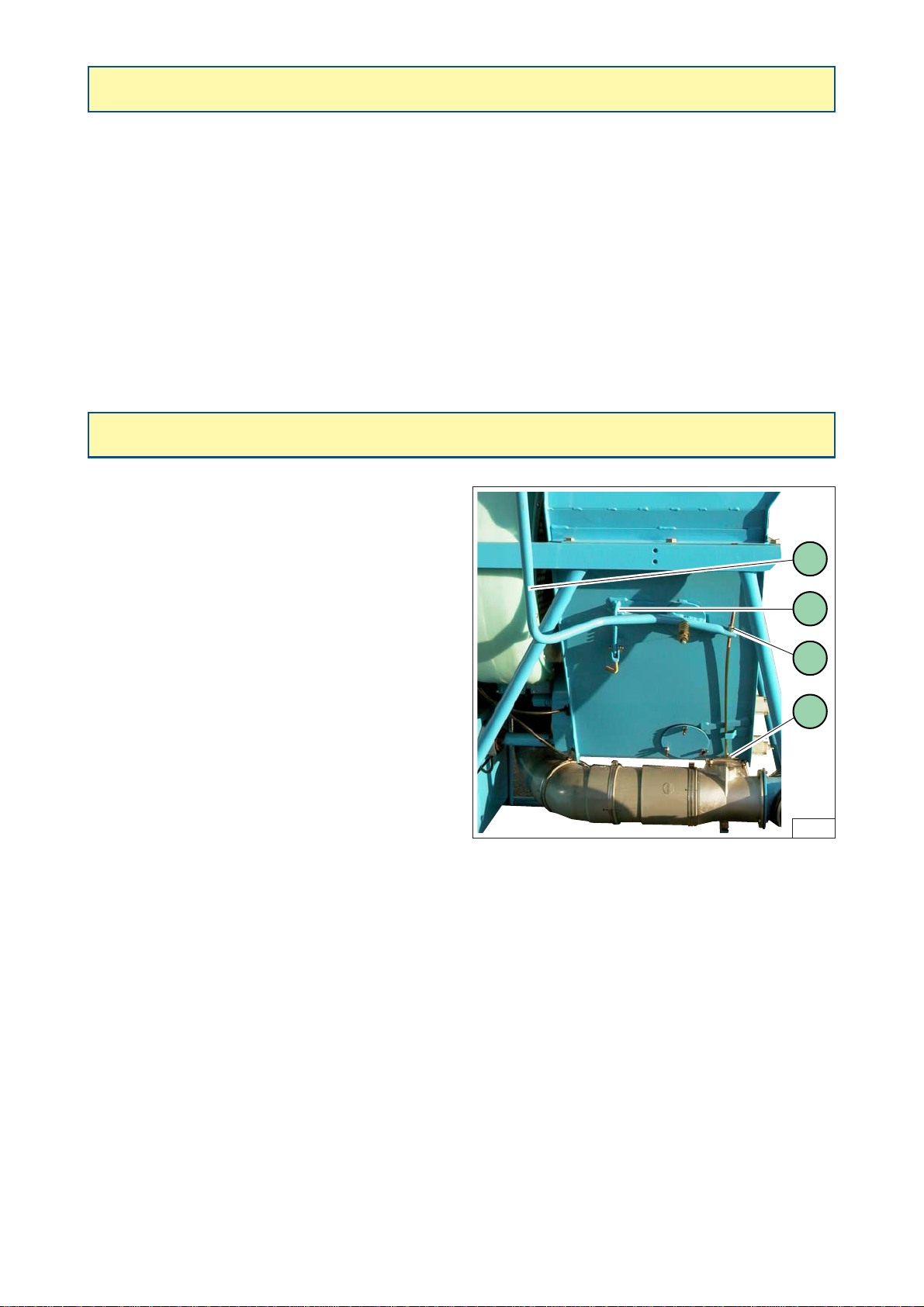
- The feed pipe to the swivelling venturi nozzle is
blocked by powder adhering to the walls due to
humidity.
- Disassemble the fixed venturi by removing the
4 nuts (2) attaching it to the hopper.
- Loosen the connecting collar (3) on the
ventilationpipe.
- Clean the powder feed pipe so that the walls
arecompletely smooth.
- Before reassembling, check that the flow rate
control gate is working properly (4).
- To balance flow at the outlets:
- with the machine running:
- put the product output direction lever in the
centralposition,
- loosen the nuts (e),
- use a screwdriver to adjust the balancing
screw (v).
- Theagitator must notdisengage if thereisno foreign
body.
- To increase or decrease torque, turn the screw (v).
CLOGGING IN THE PRODUCT FEED VENTURI NOZZLE (figure 4)
FLOW BALANCING (figure 5)
TORQUE LIMITER (figure 6)
4
4
2
3
6
v
5
e
v

16

17
DETERMINATION OF THE FLOW RATE

18
7
5
4
13.5
10
8
25
19
15
33
25
20
41.5
31
25
55
41
33
58
44
35
- These flow rates have been determined using fluid sulphur (fluidosoufre). They are therefore indicative and
significant differences may arise with powders which are more or less fluid.
- To obtain flow rates corresponding to different treatment widths, apply the following coefficients.
example:
- width 3 m: double the 6 m indications,
- width 12 m: divide the 6 m indications by 2.
Flow rates in kg/hectare according
to the forward speed
4 km/h 5 km/h 6 km/h
Selecting the
notch No. Flow rates /
minute Width
treated
6 m
8 m
10 m
6 m
8 m
10 m
6 m
8 m
10 m
6 m
8 m
10 m
6 m
8 m
10 m
6 m
8 m
10 m
6 m
8 m
10 m
2
3
4
5
6
7
8
0.4 kg
0.8 kg
1.5 kg
2.0 kg
2.5 kg
3.3 kg
3.5 kg
10
7.5
6
20
15
12
37.5
28
22.5
50
37.5
30
62.5
47
37.5
82.5
62
49.5
87.5
65.5
52.5
8
6
5
16
12
10
30
22.5
18
40
30
24
50
37.5
30
66
49.5
39.5
70
52.5
42
TABLE OF FLOW RATES

19
MAINTENANCE

20
- During the first hours of use, retighten the belts frequently.
- Remove the front cover (5) by unscrewing the nuts (6) (figure 7).
- Loosen the collar on the fan outlet tube elbow (7) (figure 7).
- Loosen the 4 screws (8) on the crosspiece (9) (figure 8).
- Unscrew the 2 nuts (10) (figure 8).
- Tighten the belts using the two tension screws (11) located under the crosspiece (figure 8).
- Retighten the nuts (10) and screws (8) (figure 8), and remount the cover (5) (figure 7).
- Lubricating the bearings: approximately every 100 hours.
- 8 greasers:
- 6 are centrally placed on the right side of the vertical support (12) (figure 9).
- 2 on the bearings (13) (figure 10).
- Use a brush to apply grease to the agitator shaft movement transmission pinions.
- Runningwithout lubricationwill resultin prematurewear.
- Recommended greases:
- After each day’s work: empty the hopper.
- Aftercleaning:openandclosetheflow regulation gate several times andleaveintheopenposition:notch No. 8.
- Carefully clean the hopper.
- Loosenthe belts.
- Unhook the return spring from the flow regulation gate which is open at its maximum position.
DRIVE MAINTENANCE
MOBILUX: Grease 2 or 3
SHELL: Alvania 2 or 3
ESSO: Beacon EP 2
MAINTENANCE DURING PERIODS OF USE
MAINTENANCE WHEN NOT IN USE
Table of contents


