Bestfilters UCT200 User manual
MODELS: UCT200
UCT100
UNDER-SINK
FILTER SYSTEMS
This System may require the
services of a licensed plumber.
UCT200 shown
with Designer Series Faucet
IMPORTANT Read and Save these Instructions
INSTALLATION, USE & CARE GUIDE
®
R 11.01 1-404-0102
QUESTIONS/COMMENTS? 1-800-842-4605 9am - 5pm Central Time
I
N
D
E
P
E
N
D
E
N
T
L
Y
•
C
E
R
T
I
F
I
E
D
•
NSF
®
System Tested and Certified by NSF International against NSF/ANSI Standard 42 for the reduction of Chlorine Taste
and Odor, and nominal Particulate Class I and NSF/ANSI Standard 53 for the reduction of Cysts, Lead, VOC and MTBE.

Introduction.................................................................................... 1
Important Use Guidelines ........................................................................ 1
Product Specifications ........................................................................... 2
Replacement Parts Directory ..................................................................... 2
Faucet Kits..................................................................................... 3
Setup and Installation ........................................................................... 4
Replacing the Cartridge.......................................................................... 9
Replacing the Battery Shuttle .................................................................... 11
Troubleshooting ............................................................................... 11
Warranty ..................................................................................... 12
TABLE OF CONTENTS
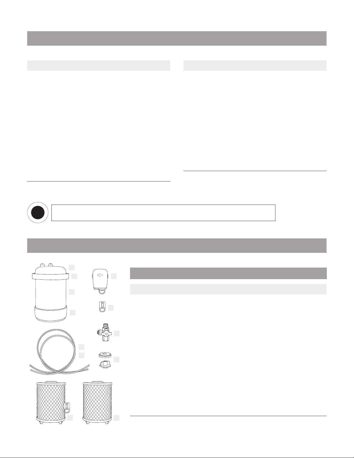
WHAT’S IN THE BOX [MODELS: UCT200, UCT100]
Designer Faucet
3/8” T Valve
Included Literature:
- Installation, Use & Care Guide
- Performance Data Sheet
LED Beauty Ring
LED Beauty Ring
Beauty Ring
(UCT100 models)
Plastic Spacer
Wing Nut
MODELS WITH VALUE FAUCET FILTER LIFE INDICATOR
(UCT200 models)
FILTER LIFE INDICATOR
(UCT200 models)
Filter Life Monitor
(includes battery and
battery shuttle)
Filter Life Monitor
(includes battery and
battery shuttle)
Value Faucet
Lid and Housing Assembly
(includes Clamp and Base)
NSF Certified
Filter Cartridge
(ships pre-installed
in housing assembly)
Red and Blue Tubing
MODELS WITH DESIGNER SERIES FAUCET
Beauty Ring
and Washer
(UCT100 models)

1
1. Replacement Cartridges may be purchased from Bestfilters®.com. For additional purchase information,
contact Customer Service at 1.800.842.4605.
2. The actual capacity of your cartridge may vary from the rated capacity. This may be due to the volume of
contaminants or sediment actually present in your water supply. Replace the Cartridge:
- Annually
- When the flow rate diminishes
- When the rated capacity of the Cartridge has been reached
- When you notice a taste or odor re-occurrence
- When the Filter Life Indicator (FLI) begins blinking Red (UCT200 models only).
3. Read this manual completely before attempting to install or use this product.
4. Do not use water that is microbiologically unsafe or of unknown quality without adequate disinfection
before or after the System.
5. Individuals requiring specific microbiological purity should consult their physician.
6. For use on cold potable water supplies only.
7. For this System to continue to perform as tested and represented, be sure to use only genuine,
NSF certified Replacement Cartridges.
8. Do not allow System to sit for extended lengths of time without being used (10 days or more). If System
must be left unused for more than 10 days, drain all water from the System and remove Cartridge. Once you
return, re-install Cartridge and flush for 15 min. prior to use (The flushed water can be used to water plants).
9. Installation of this product must comply with all state and local laws and regulations.
Refer to your local agencies for details.
10. The contaminants or other substances removed or reduced by this System may not be in all users’ water.
Congratulations on the purchase of your new, Bestfilters® Water Filter System!
You have taken an important step toward improving the quality of your drinking and cooking water.
Bestfilters® water filters have been crafted using only the finest materials and workmanship, and will serve
you reliably for many years to come when operated and maintained according to the directions contained in
this guide.
You have made a wise investment in providing quality water for you and your loved ones. Now, please take
a few minutes to make sure that you realize all the benefits your new system has to offer!
INTRODUCTION
IMPORTANT USE GUIDELINES
2
Installation. . . . . . . . . . . . . . . . . . . . . Under-Sink
Particle Retention Size . . . . . . . . . . . . . . Sub-Micron
Filter Life Indicator (FLI) . . . . . . . . . . . . . . . . . .LED
Rated Capacity. . . . . . . . . . . . . . . . 1000 gallons (US)
Rated Service Flow . . . . . . . . . . . . . . . 0.75 gal/min
Maximum Working Pressure . . . . . .125 psig (861.8 kPa)
Minimum Working Pressure . . . . . . . 30 psig (206.8 kPa)
Maximum Operating Temperature . . . . . . . 100˚ F / 38˚ C
Minimum Operating Temperature . . . . . . . . .34˚ F / 1˚ C
Replacement Cartridge (with battery & shuttle) . . . REPUCT200
EPA Establishment Number . . . . . . . . . . 63018-NV-001
UCT200 UNDER-SINK WATER FILTER UCT100 UNDER-SINK WATER FILTER
Installation. . . . . . . . . . . . . . . . . . . . . Under-Sink
Particle Retention Size . . . . . . . . . . . . . . Sub-Micron
Rated Capacity. . . . . . . . . . . . . . . . 600 gallons (US)
Rated Service Flow @ 60 psi . . . . . . . . . . . 0.75 gal/min
Maximum Working Pressure . . . . . .125 psig (861.8 kPa)
Minimum Working Pressure . . . . . . . 30 psig (206.8 kPa)
Maximum Operating Temperature . . . . . . . 100˚ F / 38˚ C
Minimum Operating Temperature . . . . . . . . 34˚ F / 1˚ C
Replacement Cartridge . . . . . . . . . . . . . . REPUCT100
EPA Establishment Number . . . . . . . . . . 63018-NV-001
Refer to Performance Data Sheet for actual contaminant and substance reduction capabilities.
PARTS DIRECTORY
PRODUCT SPECIFICATIONS
ITEM PART # DESCRIPTION
1 0581-17-05 Lid Assembly
2 9-902-0002 Clamp Assembly
3 0531-04-11 Filter Housing
4 4-105-0012-01 Base
5 9-903-0035 Filter Life Monitor (includes Shuttle & Battery) (UCT200 only)
6 0581-15-05 Battery Shuttle (includes Battery) (UCT200 only)
7 3-212-0015 3/8” T Valve
8 4-600-0017 Blue Tubing (5 ft.)
9 4-600-0015 Red Tubing (5 ft.)
10 9-904-0100 Spacer & Wing Nut
11 REPUCT200 Replacement Cartridge REPUCT200
(includes Battery Shuttle and Battery) (UCT200 only)
12 REPUCT100 Replacement Cartridge REPUCT100 (UCT100 only)
I
N
D
E
P
E
N
D
E
N
T
L
Y
•
C
E
R
T
I
F
I
E
D
•
NSF
®
System Tested and Certified by NSF International against NSF/ANSI Standard 42 for the reduction of Chlorine Taste and
Odor, and nominal Particulate Class I and NSF/ANSI Standard 53 for the reduction of Cysts, Lead, VOC and MTBE.
REPLACEMENT PARTS
1
2
4
5
6
8
7
9
3
12
10
11
3
PART # DESCRIPTION
9-904-0159 Value Faucet Kit with Filter Life Indicator (Polished Chrome)
PART # DESCRIPTION
9-904-0164 Value Faucet Kit (Polished Chrome)
PART # DESCRIPTION
9-904-0160 Designer Series Faucet Kit with Filter Life Indicator (Polished Chrome)
9-904-0161 Designer Series Faucet Kit with Filter Life Indicator (Polished Brass)
9-904-0162 Designer Series Faucet Kit with Filter Life Indicator (Brushed Nickel)
9-904-0163 Designer Series Faucet Kit with Filter Life Indicator (Oil Rubbed Bronze)
PART # DESCRIPTION
9-904-0165 Designer Series Faucet Kit (Polished Chrome)
9-904-0166 Designer Series Faucet Kit (Polished Brass)
9-904-0167 Designer Series Faucet Kit (Brushed Nickel)
9-904-0168 Designer Series Faucet Kit (Oil Rubbed Bronze)
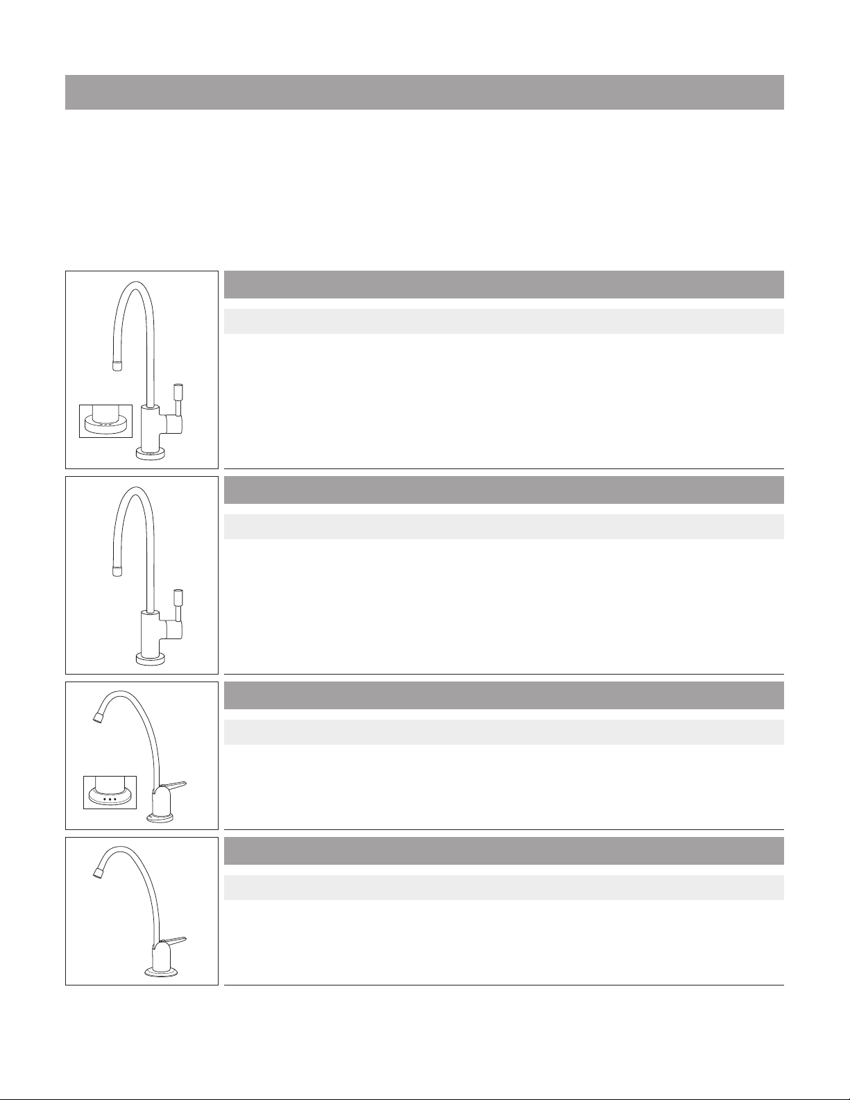
FAUCET KITS
Thinking about remodeling your kitchen? Want to add a Filter Life Indicator to your UCT100 System?
Bestfilters® Faucet Kits are available for your Under-Sink System in a variety of styles and finishes. From
our standard Value Faucet, to our premium Designer Series Faucets (available in four stunning finishes),
you’re sure to find a faucet to compliment your kitchen décor. If you’d like to add an electronic Filter Life
Indicator
to your UCT100 System, a Faucet Kit with Filter Life Indicator will convert it to a UCT200 System!
VALUE FAUCET KIT (with Filter Life Indicator)
VALUE FAUCET KIT
DESIGNER SERIES FAUCET KITS (with Filter Life Indicator)
DESIGNER SERIES FAUCET KITS
Faucet Kits include all miscellaneous installation hardware.

4
SETUP & INSTALLATION
1. Open the shipping carton, remove all System parts and place
them on your kitchen counter.
2. Compare them with the parts shown in this guide to be certain
all items were included (see inside front cover).
3. The type of plumbing that you have in your home will determine
the method of installation and type of hardware that will be used.
4. Following is a list of common tools required for most
under-counter installations:
Drilling a hole in a Porcelain/Ceramic Sink (fig. A):
3/8” Electric Drill
9/16” Carbide Masonary Drill Bit
9/16” High Speed Drill Bit
Hammer
Punch
Masking Tape
Drilling a hole in a Stainless Steel Sink (fig. B):
3/8” Electric Drill
9/16” High Speed Drill Bit
1/8” High Speed Drill Bit
Hammer
Punch
Masking Tape
Installing the 3/8” T Valve and Faucet (fig. C):
5/8” Open End Wrench
Knife
INSTALLATION QUESTIONS?
Call Customer Service at 1-800-842-4605 (M - F, 9am - 5pm Central Time)
A
B
C
1
1
3
3
2
2
4
4
1
2
5
5
6
6
1
1
1
3
3
5
5
2
2
2
4
4
6
6
5
SETUP & INSTALLATION
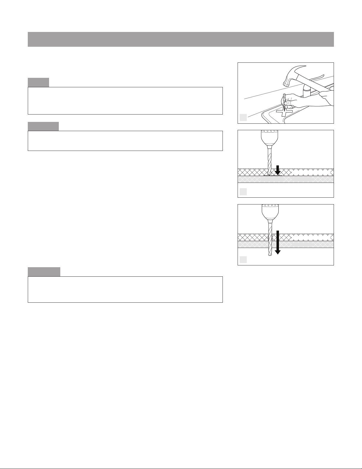
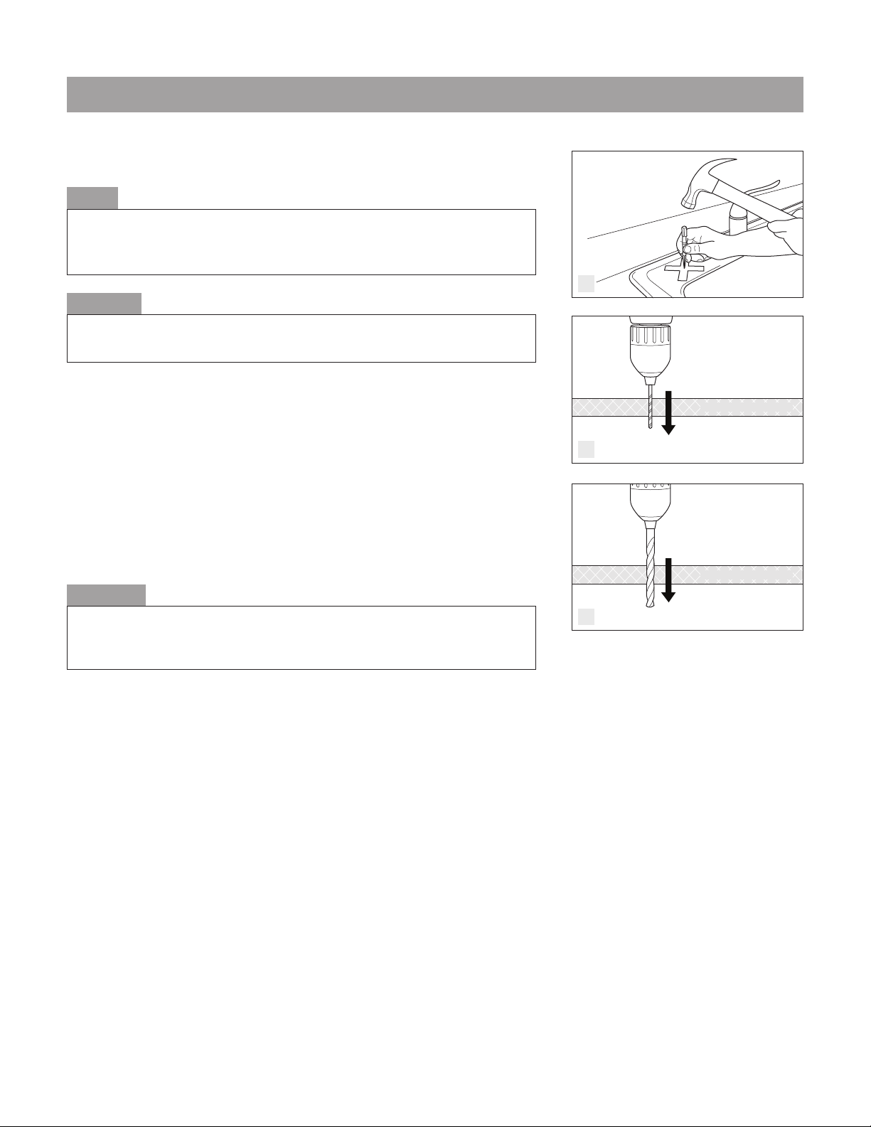
Drilling a Hole in a Porcelain/Ceramic Sink:
1. Locate an area on your sink to install the System Water Faucet
(make certain that there are no support ribs under the sink
in that location). Cover the designated location for the faucet
installation on sink with masking tape. Use the punch and
hammer to lightly score the porcelain at the designated location
for the faucet installation. (fig. D)
2. Use the 9/16” masonary drill bit to remove the porcelain down
to the metal. Drill slowly or at half speed. (fig. E)
3. Use the 9/16” high speed drill bit to drill through the exposed
surface of the metal. Hold the drill in the upright position to avoid
catching the edge of the porcelain with drill bit. (fig. F)
Proceed to “Faucet Installation” instructions on page 7.
CAUTION
This type of sink can chip easily. Use extreme care. If you have any doubts about
doing this yourself, consult a licensed plumber.
NOTE
If your sink has another hole that currently has a spray attachment, you may
decide to remove the spray attachment and use the existing hole to continue
your installation (skip the next section and go to “Faucet Installation” on page 7).
WARNING
Use EXTREME CAUTION with electric power tools near water. Ensure that there
is no standing water in the sink and that the area is dry. Failure to follow this
warning could result in serious injury or death.
F
D
E
9/16 Masonary Drill Bit
9/16 High Speed Drill Bit
Sink Cross-section:
Sink Cross-section:
Porcelain/Ceramic Layer
Porcelain/Ceramic Layer
Metal Layer
Metal Layer
STOP at Metal
SETUP & INSTALLATION
6
Drilling a hole in a Stainless Steel Sink:
1. Locate an area on your sink to install the System Water Faucet
(make certain that there are no support ribs under the sink in
that location). Cover the designated location for the faucet
installation on sink with masking tape. Use the punch and
hammer to make a light indentation at the designated location
for the faucet installation. (fig. G)
2. Using a 1/8” high speed drill bit, drill a pilot hole. (fig. H)
3. Use a 9/16” high speed drill bit to enlarge the pilot hole. (fig. I)
Proceed to “Faucet Installation” instructions on page 7.
WARNING
Use EXTREME CAUTION with electric power tools near water. Ensure that there
is no standing water in the sink and that the area is dry. Failure to follow this
warning could result in serious injury or death.
CAUTION
This type of sink can be scratched easily. Use extreme care. If you have any
doubts about doing this yourself, consult a licensed plumber.
NOTE
If your sink has another hole that currently has a spray attachment, you may
decide to remove the spray attachment, and use the existing hole to continue
your installation (skip the next section and go to “Faucet Installation”).
1/8” High Speed Drill Bit
9/16” High Speed Drill Bit
Steel Sink Cross-section
Steel Sink Cross-section
G
H
I
7
SETUP & INSTALLATION
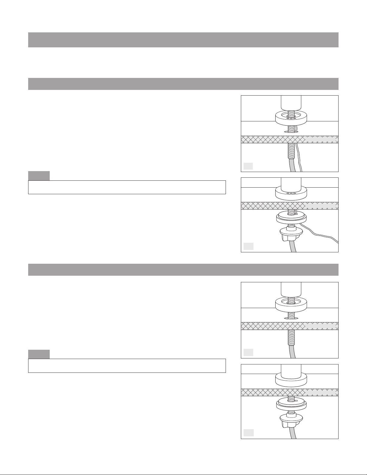
Faucet Installation:
1. Slide the LED Beauty Ring up Faucet Tubing and onto Faucet
Stem. Next, insert Cable through hole in sink, followed by Faucet
Tubing and Faucet Stem. (fig. J-1)
2. From under the sink, guide the Cable through the hole in
Spacer (small side up). Now insert the Faucet Tubing through
the hole in Spacer and guide Spacer onto Faucet Stem.
Thread Wing Nut onto Faucet Stem and hand tighten. (fig. J-2)
Proceed to “System Installation” instructions on page 8.
1. Slide the Beauty Ring (and Washer on Value Faucet Model) up
Faucet Tubing and onto Faucet Stem, then insert Faucet Tubing
and Stem through hole in sink. (fig. K-1)
2. From under the sink, insert Faucet Tubing through the hole in
Spacer (small side up) and guide Spacer onto Faucet Stem.
Thread Wing Nut onto Faucet Stem and hand tighten. (fig. K-2)
Proceed to “System Installation” instructions on page 8.
NOTE
Final Faucet positioning may require two people when Wing Nut is tightened.
NOTE
Final Faucet positioning may require two people when Wing Nut is tightened.
K-1
K-2
J-1
J-2
System Faucet
Faucet Stem
Faucet Stem
Blue Tubing
Blue Tubing
Spacer
Spacer
Wing Nut
Wing Nut
LED Beauty Ring
Beauty Ring
Cable
Cable
Sink Cross-section
Sink Cross-section
Sink Cross-section
Sink Cross-section
System Faucet
UCT200 MODELS (Faucets WITH Filter Life Indicator)
UCT100 MODELS (Faucets WITHOUT Filter Life Indicator)

8
SETUP & INSTALLATION
L
M
N
O
P
2
1
STEP
3
STEP STEP
Red Tubing
Compression Nut
Compression Nut
3/8” T Valve
Cold Water
Supply Line
Cold Water
Supply Line
Red Tubing
(from 3/8” T Valve)
Inlet Connector
Outlet Connector
System Installation:
1. Using the 5/8” open ended wrench, unthread the compression
nut located on top of the shut-off valve located on existing cold
water supply line. (fig. L)
2. Thread the 3/8” T Valve onto cold water supply line, and tighten
with the 5/8” open ended wrench (fig. M, Step 1). Next, thread
the compression nut onto the top of 3/8” T Valve and tighten
(fig. M, Step 2). Lastly, press the Red Tubing into the Outlet Connector
located on 3/8” T Valve (fig. M, Step 3).
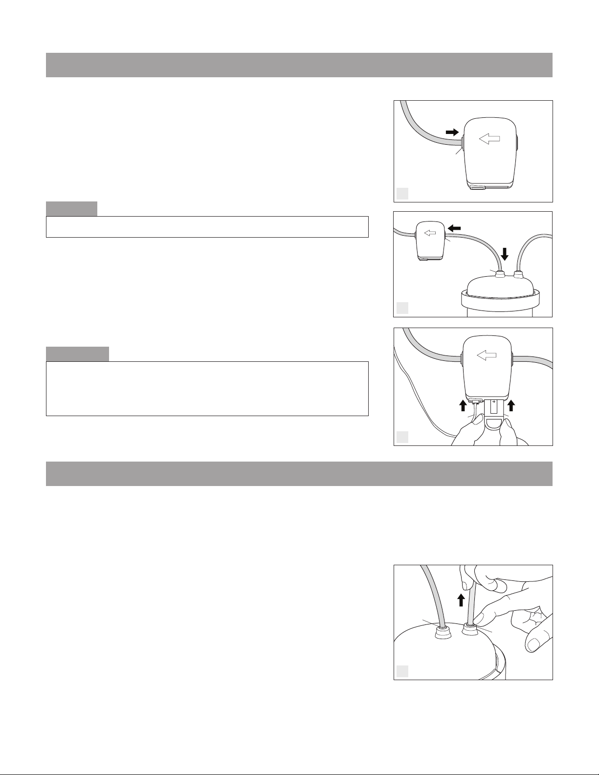
3. Press opposite end of Red Tubing into Inlet Connector located on
top of Lid Assembly. (fig. N)
4. UCT100 MODELS: Push the Blue Tubing from the System Faucet
into the Outlet Connector located on top of Lid Assembly. (fig. O)
(Skip to instruction number 8.)
UCT200 MODELS (with Filter Life Indicator): Locate an area on
cabinet wall to mount the Filter Life Monitor. Secure Filter Life
Monitor to the wall using the Velcro Adhesive Strips provided. (fig. P)
IMPORTANT
Before attempting this installation, be certain to turn “OFF” the cold water supply
located under your sink. If a shut-off valve is not located on the cold water line
directly under your kitchen sink, shut off the main water supply to your home.
RECOMMENDATION
You may want to reduce the length of the Red Tubing if you find there is excess.
However, it is advisable to leave the Red and Blue Tubing long enough so that
the System can be easily removed from under the counter when it’s time to
replace the Cartridge.
CAUTION
Use a sharp knife when cutting Tubing. Take extra care not to distort Tubing
while cutting. Cut Tubing end straight. Failure to do so may result in leaking.
NOTE
Locate an area under the kitchen sink to place the Base. The Base should be
located directly under the area where the Faucet will be installed.
NOTE
If you find that it is necessary to remove the tubing from Inlet or Outlet Connectors,
depress the small collar located on the Inlet and Outlet Connectors and pull
Tubing upward at same time.
Blue Tubing
(from System Faucet)
Velcro Strip
(on cabinet wall) Filter Life
Monitor
9
- Annually
- When the flow rate diminishes
- When the rated capacity of the Cartridge has been reached
- When you notice a taste or odor re-occurrence
- When the Filter Life Indicator begins blinking red (UCT200 models)
1. Turn “OFF“ the cold water supply to the System. Depress the small
Collar located on the Inlet Connector of the Lid Assembly while
pulling Red Tubing upward. Repeat procedure for removing the
Blue Tubing from the Outlet Connector. (fig. T)
(continued on following page)
The most important part of maintaining your Bestfilters® water filter is replacing the Cartridge (and battery
in UCT200 models) on a regular service interval. To insure your System continues to perform as stated in the
Performance Data Sheet, the Cartridge should be replaced upon the first occurrence of the following:
SETUP & INSTALLATION
REPLACING THE CARTRIDGE
Q
R
S
T
5. Push the Blue Tubing from the System Faucet into the Outlet
Connector located on Filter Life Monitor. (fig. Q)
6. Using the other piece of Blue Tubing provided, push one end of
the Tubing into Outlet Connector located on Lid Assembly, and
remaining end of Tubing into the Inlet Connector located on
Filter Life Monitor. (fig. R)
7. Insert Cable Connector into Cable Port located on Filter Life
Monitor, then insert Battery Shuttle into Battery Port located on
Filter Life Monitor. (fig. S)
8. Slowly turn “ON” cold water supply and check for leaks. Then
turn “ON” System Faucet and allow System to flush into sink for
15 minutes. Return System Faucet to “OFF” position.
Congratulations! Your new Bestfilters® water filter is ready!
IMPORTANT
Before using this System, or whenever a new Cartridge is installed, be sure to
allow the System to flush for 15 minutes (This water may be used to water plants).
This procedure will remove carbon particles left over from the manufacturing
process, expel trapped air and condition the Cartridge for normal use.
CAUTION
Be sure to leave enough Tubing length so that it does not kink or bend sharply.
Outlet
Connector
Outlet
Connector
Inlet
Connector
Cable Battery Shuttle
Filter Life
Monitor
Blue Tubing
(from System
Faucet)
Blue Tubing
Inlet
Collar
Outlet
Collar
Blue
Tubing Red
Tubing
REPLACING THE CARTRIDGE
10
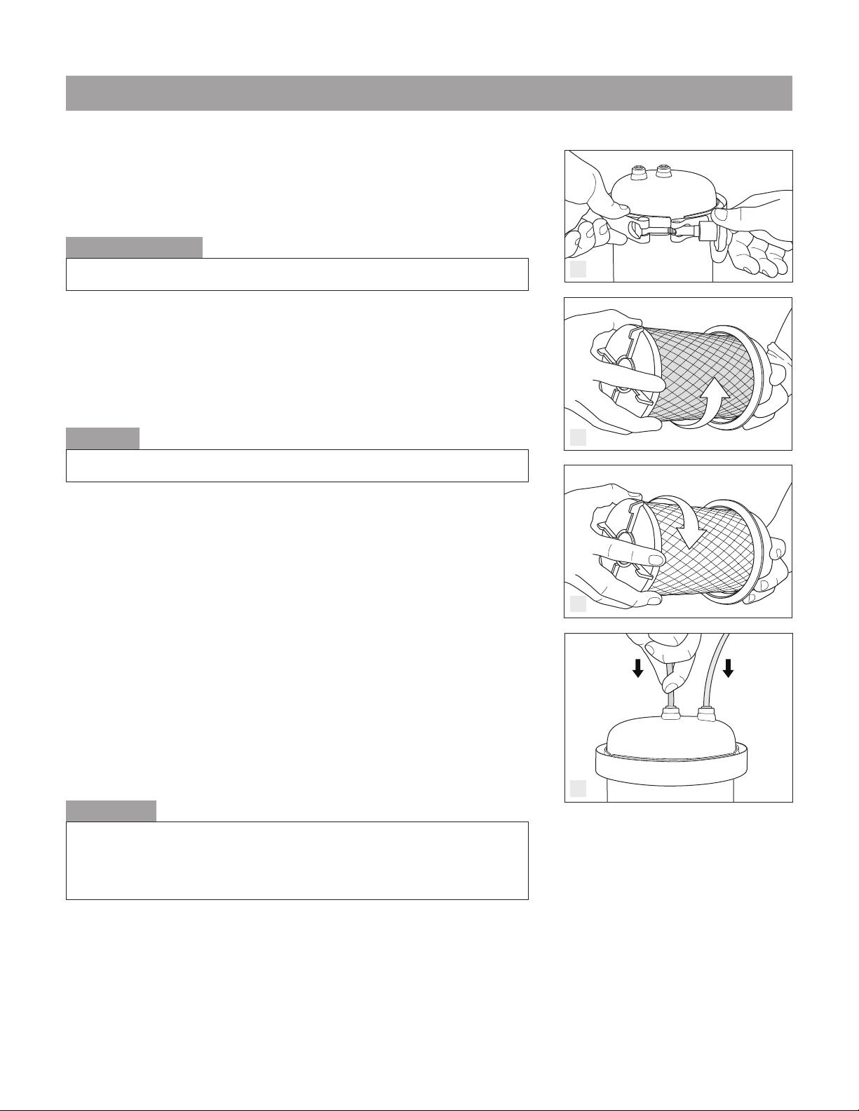
2. Place a towel or other soft object in sink to prevent damage to
System. Remove Filter Housing from Base and set in sink. Turn
knob located on Clamp counter clockwise to loosen. Remove
Clamp from Lid Assembly and Filter Housing. (fig. U)
3. Lift Lid Assembly from Filter Housing. While holding Lid Assembly,
turn Cartridge counter-clockwise to remove. Discard with
regular refuse. (fig. V)
4. Wash inside of Lid Assembly and Filter Housing with warm water,
mild dishwashing detergent and a clean cloth.
5. Remove plastic sanitary wrap from new, Bestfilters®
Replacement Cartridge. Thread the new Cartridge clockwise onto
the Threaded Post inside Lid Assembly until you feel resistance.
Make an additional quarter turn. Do not over-tighten. (fig. W)
6. Make certain O-Ring is seated on Lid Assembly. Place Lid Assembly
onto Filter Housing, and place Clamp around Lid Assembly and
Filter Housing. Tighten Knob on Clamp securely.
7. Place Filter Housing into Base. Insert Blue Tubing end into Outlet
Connector and Red Tubing end into Inlet Connector on Lid
Assembly. Re-position System under your sink. (fig. X)
8. Slowly turn “ON” cold water supply and check for leaks. Then
turn “ON” System Faucet and allow System to flush into sink for
15 minutes. Return System Faucet to “OFF” position.
IMPORTANT
Before using this System, or whenever a new Cartridge is installed, be sure to
allow the System to flush for 15 minutes (This water may be used to water plants).
This procedure will remove carbon particles left over from the manufacturing
process, expel trapped air and condition the Cartridge for normal use.
RECOMMENDATION
Rubber gloves should be worn to avoid direct contact with filtered contaminants.
CAUTION
Do not use abrasive pads or other abrasive materials to clean System.
V
W
Blue Tubing from
System Faucet
Red Tubing from
3/8” T Valve
Blue Tubing Red Tubing
Outlet Connector Inlet Connector
X
U
Old Cartridge
Replacement Cartridge
Gloves
REPLACING THE BATTERY SHUTTLE (UCT200 models only)
TROUBLESHOOTING
11
CONDITION:
White sediment is in my filtered water.
REASON:
There is a presence of calcium carbonate in your
main water supply. This condition will occur any
time the filtered water is boiled or frozen and
then melts.
SOLUTION:
This condition is normal – no action is required.
However, you may choose to strain the white
sediment.
CONDITION:
Filtered water is flowing slowly from the System.
REASON:
Excessive amounts of particles in the water supply
may have caused pre-mature plugging of the
Cartridge. On models equipped with a Filter Life
Indicator, this condition may occur before the Red
Lamp begins to flash.
SOLUTION:
The Cartridge must be replaced due to poor water
quality conditions in your area.
NOTE: For UCT200 models, the Battery and Battery
Shuttle must also be replaced at time of Cartridge
replacement. (Included with REPUCT200 Cartridge.)
CONDITION:
Ice cubes appear cloudy in the center.
REASON:
Minerals such as calcium and magnesium that
are present in your water supply and collect in
the center of ice cubes when water is frozen. Your
System is designed specifically to leave beneficial
trace minerals in your water.
SOLUTION:
No action is required
CONDITION:
The Yellow Lamp on System Faucet LED Beauty Ring
is flashing (UCT200 models only).
REASON:
The Cartridge is reaching the end of its rated
capacity and will need to be replaced soon.
SOLUTION:
Purchase a new Bestfilters® Replacement Cartridge
by calling Customer Service at 1.800.842.4605, or
ordering online from www.bestfilters.com. Once
the Red Lamp begins blinking, it is time to replace
the used Cartridge and Battery Shuttle.
NOTE: REPUCT200 Replacement Cartridges include new
Battery and Battery Shuttle.
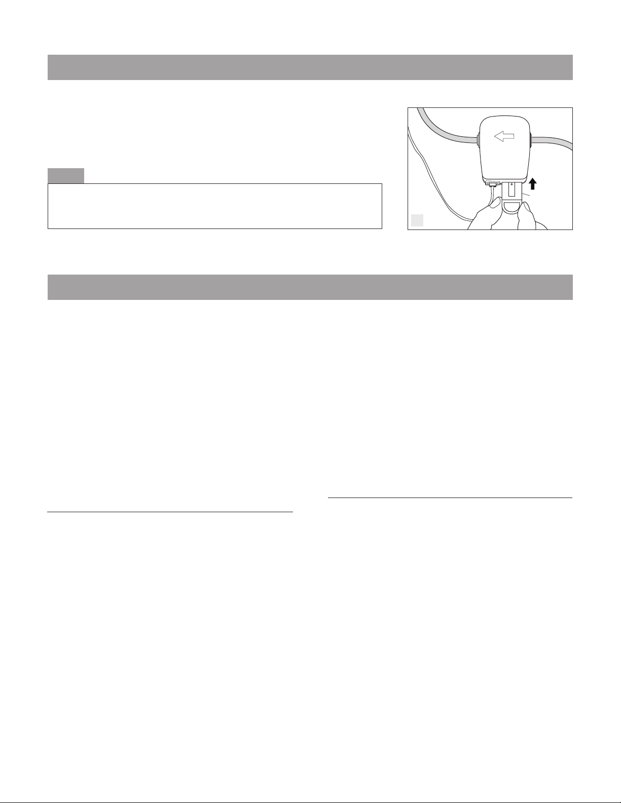
1. Remove Battery Shuttle from Filter Life Monitor and discard.
2. Insert new Battery Shuttle (included with your replacement
cartridge) into Battery Port located on Filter Life Monitor. (fig. Y)
NOTE
The Beauty Ring has embedded LEDs that will cycle green, yellow and red three
times. This resets the Filter Life Monitor to zero gallons, which is the starting
point for a new Cartridge.
New Battery
Shuttle
Y

UNDER-SINK FILTER SYSTEM
®
TWO YEAR LIMITED WARRANTY
Bestfilters®.com warrants that for a period of two years from the date of purchase, this product will
be free from defects in material and workmanship.
Bestfilters®.com, at its option, will repair or replace this product or any component of the product
found to be defective during this warranty period. Replacement will be made with a new or
remanufactured product or component. If the product is no longer available, replacement may be
made with a similar product of equal or greater value. This is your exclusive warranty. This warranty is
valid for the original retail purchaser from the date of original retail purchase and is not transferable.
Keep the original sales receipt. Proof of purchase is required to obtain warranty service.
This warranty does not cover normal wear of components or damage resulting from any of the
following: negligent use or misuse of the product, use contrary to the Installation, Use & Care
Guide, disassembly, repair or alteration by anyone other than Bestfilters®.com or an authorized
service center. Further, the warranty does not cover acts of nature, such as fire, flood, tornadoes
or hurricanes.
Bestfilters®.com shall not be liable for any incidental or consequential damages caused by the
breach of any express or implied warranty. Except to the extent prohibited by applicable law, any
implied warranty or merchantability or fitness for a particular purpose is limited in duration to the
duration of the above warranty. Some states, provinces or jurisdictions do not allow the exclusion or
limitation of the incidental or consequential damages or limitations on how long an implied warranty
lasts, so the above limitations or exclusion may not apply to you. This warranty gives you specific
legal rights, and you may also have other rights that vary from state to state or province to province.
HOW TO OBTAIN WARRANTY SERVICE
Call us at: 1.800.842.4605, or email us at info@bestfilters.com for a Return Authorization Number
and instructions for shipment. Products returned without a Return Authorization Number will be refused.
If it is determined that it is necessary to return the product, be certain to pack it in the original carton,
or equivalent, using newspaper, or other packing materials to protect the product from damage in
transit. Before sealing the carton, be sure to include a copy of the original sales receipt along with a
note describing the nature of the defect, or problem. Also be certain to include your return shipping
address and write the Return Authorization Number on the outside of the carton.
Send the product shipping pre-paid to: Bestfilters®.com, LLC.
Attn: Customer Service
11068 Little Elm Road
Farmington, AR 72730
Upon receiving the product, we will repair or replace the product and return it to the return address
on the shipping carton, shipping pre-paid.


This manual suits for next models
1
Table of contents
Popular Water Filtration System manuals by other brands


Tier1
Tier1 WH-RO-700 user manual

Waterco
Waterco MultiCyclone 70XL user manual

aquamundus
aquamundus GreaseShield 1000-PF installation guide

globalwater
globalwater AquaWave Classic 75GPD Installation, operation & maintenance manual

AQUA FILTER
AQUA FILTER FHMB12 Installation and Maintenance

globalwater
globalwater G500 Installation & operating manual

Welbilt
Welbilt Dean MF90 Series Installation & operation manual

Blue Marine
Blue Marine Reactor Mini 120 instruction manual

Spring Well
Spring Well ULTRA UWS1 installation instructions

Clear Water
Clear Water Ozone Systems PRO400 Installation & maintenance manual

Pure-Pro
Pure-Pro EC106 user manual

AQUA EL
AQUA EL ULTRAMAX 1000 user manual