BETEX BLF 200 User manual

© Betex International BV, BLF, 19-08-V1
USER MANUAL
BETEX® Induction heaters
Induktionsanwärmer | Appareil de chauffe par induction | Calentador de inducción | Inductieverhitter
BETEX® BASIC Models
BLF 200
BLF 201
BLF 202
BLF 203


1. User manual……………………………………………………. 5
2. Gebrauchsanleitung………………………………………….. 24
3. Manual de uso ……………………………………………… 44
4. Manuel utilisateur…………………………………………….. 63
5. Gebruiksaanwijzing…………………………………………… 82
READ THE MANUAL AND SAFETY INSTRUCTIONS BEFORE OPERATING THE DEVICE
Check all parts for possible damage during transportation. In case of damage, please contact the carrier
immediately. Because our products are continuously subject to improvements, we reserve the right to make
changes.
VOR INBETRIEBNAHME DIE BETRIEBSANLEITUNG UND DIE SICHERHEITSVORSCHRIFTEN
AUFMERKSAM LESEN
Alle Teile auf möglichen Transportschaden kontrollieren. Eventuelle Schäden umgehend der Spedition
melden. Da unsere Produkte ständig verbessert werden, behalten wir uns Änderungen vor.
ANTES DE LA PRIMERA PUESTA EN MARCHA, LEA ATENTAMENTE EL MANUAL DE USO Y LAS
INSTRUCCIONES DE SEGURIDAD
Revise todos los elementos para detectar posibles daños sufridos durante el transporte.
En caso de observar algún daño, avise inmediatamente a la empresa de transporte.
Debido a que nuestros productos están continuamente sujetos a mejoras, nos reservamos el derecho de
realizar cambios.
LISEZ LE MODE D'EMPLOI ET LES CONSIGNES DE SÉCURITÉ AVANT LA MISE EN SERVICE
Vérifiez pour l'ensemble des pièces que celles-ci n'ont pas été endommagées pendant le transport. En cas
de dommages, avertissez immédiatement le transporteur. Nos produits étant constamment améliorés, nous
nous réservons le droit d'apporter des modifications.
LEES VOOR INGEBRUIKNAME EERST DE GEBRUIKSAANWIJZING EN DE VEILIGHEIDSVOOR-
VOORSCHRIFTEN
Controleer alle onderdelen op mogelijke transportschade. Waarschuw bij schade onmiddellijk het
transportbedrijf. Omdat onze producten voortdurend worden verbeterd, behouden wij ons het recht voor om
wijzigingen aan te brengen.

5
Table of contents EN
Table of contents............................................................................................................................... 5
1. Safety , warnings and potential hazards...................................................................................... 6
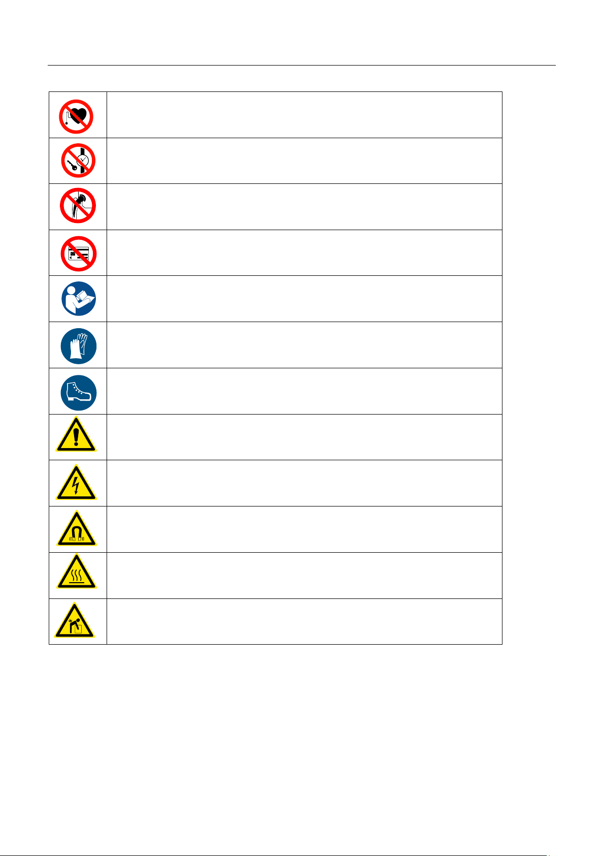
1.1 Explanation of the pictograms ................................................................................................... 6
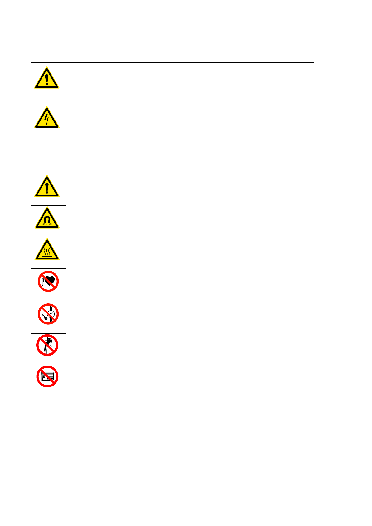
1.2 Description of potential hazards................................................................................................. 7
1.3 Safety measures to be taken ..................................................................................................... 9
1.4 Safety provisions ....................................................................................................................... 9
2. Introduction ................................................................................................................................. 10
2.1 Application............................................................................................................................... 10
2.2 Operating conditions................................................................................................................ 10
2.3 Principle of operation............................................................................................................... 10
3. Installation ....................................................................................................................................11
4. Explanation of display and keys ............................................................................................... 12
5. The magnetic temperature sensor ............................................................................................. 12
6. Method of operation.................................................................................................................... 13
6.1 Heating a hanging workpiece .................................................................................................. 13
6.2 Heating a horizontal workpiece................................................................................................ 14
6.3 Maximum weights for swivel arm models................................................................................. 15
7. Operation..................................................................................................................................... 16
7.1 Heating in temperature mode (start position of the heater) ...................................................... 16
7.2 Heating in time mode............................................................................................................... 16
7.3 Workpiece installation.............................................................................................................. 17
7.4 Error message......................................................................................................................... 17
7.5 Switching between Celsius and Fahrenheit ............................................................................. 17
8. Cleaning, maintenance and troubleshooting ............................................................................ 18
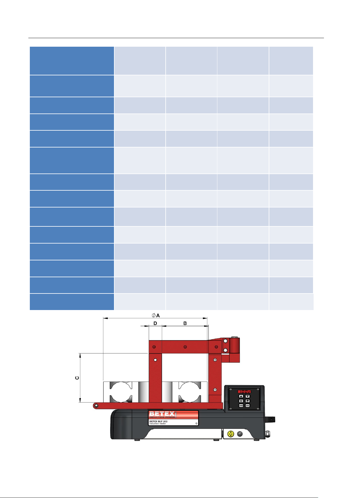
9. Technical specifications ............................................................................................................. 19
10. Miscellaneous............................................................................................................................ 20
10.1 Warranty conditions............................................................................................................... 20
10.2 Disclaimer.............................................................................................................................. 20
10.3 Waste disposal ...................................................................................................................... 20
11. Certificate of conformity ........................................................................................................... 21
Annex 1. Electrical diagrams.......................................................................................................... 22

6
1. Safety , warnings and potential hazards
1.1 Explanation of the pictograms
Forbidden for persons with heart pacemaker or other sensitive implants.
Wearing of metal parts, watches and jewellery forbidden.
Forbidden for persons with metal implants.
Forbidden for magnetically sensitive data media.
Read the user manual!
Wear heat-resistant gloves!
Wear safety shoes!
Warning of danger.
Electric shock hazard.
Warning of magnetic fields.
Warning of hot surface.
Warning of heavy object.

7
1.2 Description of potential hazards
Warning! Voltage
Be aware that you are working with an electrical appliance. On the mains side
as well as internally, voltages occur that can lead to serious injury and death if
used inexpertly or improperly.
- Connect the unit to the mains according to the information on the rating
plate.
- Before each use, check the power supply cable for damage.
- Safe disconnection from the mains supply must be ensured at all times
before starting maintenance and repair work. This can be achieved by
removing the mains plug from the socket.
Warning! Electromagnetic field
Be aware that you are working with an appliance that generates
electromagnetic fields. Keep a distance of 1 metre from the unit when switching
on.
These fields can be harmful for persons with active medical aids such as heart
pacemakers.
These fields can be harmful for persons with passive medical aids such as joint
prostheses. The wearing of jewellery can also result in injuries due to burns.
It is forbidden for persons with active medical aids to be in the immediate
vicinity of the unit when it is in operation. The generated electromagnetic field
may influence the proper function of such medical aids.
It is forbidden to wear jewellery when working with the generator and inductors.
There is a risk of the jewellery being heated by the electromagnetic field and
resulting in injuries due to burns.
For this reason, persons with passive implants are recommended not to enter
the immediate vicinity of the induction heater when it is in operation.
Furthermore, it cannot be ruled out that the electromagnetic fields could cause
damage to electronic and magnetic data media. Keep such equipment away
from the induction heater.

8
Caution! Tripping hazard
Limit the risk of injury due to tripping as far as possible.
- Keep your place of work tidy. Remove any loose and superfluous objects
from the immediate vicinity of the unit.
- Position any (power supply) cables as low as possible to minimise the risk
of tripping.
Caution! Risk of burns
The workpiece becomes warm to very hot during heating.
Parts of the unit may also become hot due to contact with the workpiece or the
heat radiated by the workpiece.
Therefore always wear heat-resistant gloves when handling workpieces in
order to avoid injury due to burns.
Caution! Risk of injury during lifting
A number of units in the Betex heater range weigh more than 23 kg and may
therefore not be lifted by one person alone. (see technical specs)
If a unit weighs more than 23 kg, lift it with two persons or use suitable lifting
equipment.
Wear safety shoes to prevent injury from unintentionally falling workpieces
and/or machine parts.

9
1.3 Safety measures to be taken
•The user must carefully read this manual and be familiar with the safety standards in the work
practice.
•Follow the instructions in the manual at all times.
•Check the connection voltage against the rating plate on the unit. If the power cord does not have
one, make sure it is fitted with the proper plug. This must be fitted by a qualified electrician.
•Never use or store an induction heater in a damp environment.
Only use Betex induction heaters indoors.
•If using a mobile version; always lock the castors when not moving the device.
•If the heater is equipped with extendable horizontal supports, always secure them with the
appropriate locking pin, both in the fully retracted and in the fully extended position.
•Use suitable lifting equipment according to the weight of the yoke or component.
•Never use a metal strap to support workpieces or suspend them in the magnetic field. High
currents could start running through the strap, causing it to heat up.
•Do not hold metal objects near yoke and poles.
•Whilst heating, observe a minimum distance of 1 metre from the heater.
•Never remove the induction yoke during heating.
•Do not modify the heater. Never use home-made yokes.
•Always check that the induction yoke is positioned correctly against the poles, so excessive
vibration cannot cause personal injury or damage to the device.
•Do not switch on the heater until the core is closed with a yoke.
1.4 Safety provisions
•The electronic systems switch off automatically if the ambient temperature rises above 70ºC.
•When heating in temperature mode, the heater switches off if no 1°C temperature increase is
measured during a time pre-set by the manufacturer.
•The coil of the heater is equipped with a temperature monitor. If the coil becomes too hot, the
heating process is switched off entirely.
•Models with a swivel arm are equipped with a safety positioning cam.
WARNING!
We recommend that people be kept at least 1 metre away from the device once it
has been switched on.

10
2. Introduction
2.1 Application
Betex induction heaters are intended for heating bearings, so they can be assembled easily by means
of a shrink fit. Subject to professional assessment, they can also be used to heat bushes, cogwheels,
couplings and metal objects that form a closed circuit. Bearings and workpieces are demagnetised
automatically after each heating cycle.
Bearings and workpieces can be heated to a maximum temperature of 240ºC (464°F), except for the
Betex BLF200 type where the maximum temperature is set at 150ºC (300°F).
Betex induction heaters are suitable for continuous use. However, when heating to 240°C (464°F), we
recommend that you do not do so for more than half an hour. Use an external thermometer.
CAREFUL!
•Bearings may be heated to a maximum of 120°C (248°F).
•Precision bearings may be heated to a maximum of 70°C (158°F). Higher temperatures can
affect metallurgical structure and lubrication, resulting in instability and failure.
•Do not use a heater for bearings and workpieces that are outside the minimum and maximum
dimensions specified in the technical specifications.
•Never switch off the unit with the main switch while it is still heating up.
2.2 Operating conditions
•Only use the device indoors.
•Fit for use in an industrial environment, at an ambient temperature of 0ºC (32°F) to 50ºC (120°F)
and humidity of 5 to 90% – non-condensing.
At temperatures below 0°C (32°F), the unit stops operating.
2.3 Principle of operation
The operation of the heater is based on inducing a (low frequency) current in
the bearing. This is achieved by incorporating the bearing as a secondary
winding in a transformer.
The primary winding is connected to the mains by means of an electronic
controller. The magnetic field induces a high current (short-circuit current)
through the bearing, which then becomes hot. After each heating cycle, the
bearing or workpiece is demagnetised.

11
3. Installation
•Remove the packaging and place the induction heater on a non-ferrous, stable and level
surface. Put heaters with wheels on the brake to prevent the heaters from moving.
•A Betex heater is supplied with yokes, temperature sensor, heat-resistant gloves (suitable up to
250°C / 482°F) and acid-free Vaseline.
•Check the connection voltage against the rating plate on the unit.
•Each heater is equipped with a plug. As there is a wide variety of plug types, the attached plug
may not fit. In such cases, obtain a proper plug. It must be fitted by a qualified electrician.
There are 2 fitting options depending on the type of cable on the heater:
120V/230V 1 phase heaters
120V/230V 1 phase heaters cCSAus
brown
phase
black
phase
blue
zero
white
zero
green/yellow
earth
green
earth
•Ensure that the power supply cable cannot come into contact with the workpiece to be heated.
Insert the plug in a socket outlet with earth connection.
•Switch on the device by means of the main switch. The machine briefly shows “Test”, and the
display shows a “pre-set end temperature” programmed by the manufacturer.
•Connect the temperature sensor by inserting the plug into the socket. Make sure that the – and +
of the plug correspond to that of the socket.
•The induction heater is now ready for use in the temperature mode.

12
4. Explanation of display and keys
5. The magnetic temperature sensor
•The magnetic temperature sensor (sensor) must always
be used when heating in “temperature mode”
•The sensor can be used as a tool for temperature
control whilst heating in “time mode”
•The sensor is suitable for a maximum temperature of 240ºC (464°F).
•In the event of temperatures exceeding 240ºC (464°F), the connection between the magnet and
the sensor is interrupted. The heater switches off automatically when the sensor does not detect a
temperature increase.
•Special clamp sensors are available for non-magnetic workpieces.
• Make sure that the sensor and workpiece surfaces are clean.
•Always place the sensor on a flat area as
close as possible to the bore. Connect the
sensor by inserting the plug into the
socket (in the casing). Make sure that the
– and + of the plug correspond to that of
the socket.
CAREFUL!
•Handle the sensor with care! It is a vulnerable part of the heater. After use, place the sensor on
the side of a vertical pole.
Time or temperature up -
Heating in temperature mode -
Start heating after setting
time/temperature -
- Display: time or temperature
- Time or temperature down
- Heating in time mode
- Stop heating / automatic
demagnetise

13
6. Method of operation
WARNING!
Use suitable lifting equipment for heavy yokes and workpieces. Prevent personal
injury by improper handling.
The weight of the workpiece may not exceed the value given in section 6.3 and in
the technical specifications. This can cause failure of the device and personal
injury.
Ensure that the power supply cable cannot come into contact with the workpiece to
be heated. Damage to the cable can cause electrocution!
Never use a metal strap to support workpieces or suspend them in the magnetic
field. High currents could start running through the strap, causing it to heat up.
A workpiece can be placed in 2 different ways:
Hanging, with yoke through the workpiece
Horizontal, with workpiece around the pole
Large workpieces can be thermally insulated by wrapping them in insulating material, such as a
welding blanket. This ensures that the heat stays in the workpiece and does not dissipate.
6.1 Heating a hanging workpiece
•Place the induction yoke with the
bearing on the poles. Make sure that the
ground side is positioned straight on the
poles.
•Always choose an induction yoke that
fills the bore of the bearing as much as
possible. You can even use 2 yokes at
the same time. This promotes optimal,
fast and even heating.
•Make sure that the bare-metal sides are
sufficiently coated with Vaseline to
ensure optimal contact and avoid
vibration.

14
•Swivel arm models: swivel the yoke open (towards you) until it clicks in the safety positioning cam.
Slide the workpiece over the yoke until it is in the middle.
Swivel the yoke back to the pole.
•Always make sure that the workpiece does not come into contact with the plastic casing of the
heater. When the heating is finished, follow the instructions in reverse order. Use heat-resistant
gloves to move the heated workpiece.
6.2 Heating a horizontal workpiece
•Always make sure that the workpiece does not come into contact with the plastic casing of the
heater. When the heating is finished, follow the instructions in reverse order. Use heat-resistant
gloves to move the heated workpiece.
•This is only possible if the bore of the workpiece is large enough to fit over the pole.
•Place the workpiece as centrally as possible around the pole on the horizontal supports.
•The workpiece may not be wider than the horizontal supports.
•Always choose the largest induction yoke.
•Make sure that the bare-metal sides are sufficiently coated with Vaseline to ensure optimal contact
and avoid vibration.

15
6.3 Maximum weights for swivel arm models
Table for maximum permitted weights on the horizontal support and the (swivel) yokes:
Size of (swivel) yoke
Type
on
supports
7 mm
10
mm
14
mm
20
mm
30
mm
40
mm
50
mm
60
mm
70
mm
BLF 200
n/a
1 kg
2 kg
3 kg
5 kg
n/a
20 kg
n/a
n/a
n/a
BLF 201
50 kg
10 kg
15 kg
n/a
n/a
n/a
BLF 202
100 kg
n/a
20 kg
n/a
n/a
BLF 203
150 kg
n/a
n/a
n/a
10 kg
15 kg
25 kg
40 kg
45 kg
50 kg
•Keep to these maximum weights and avoid tilting the heater or damaging the supports, (swivel)
yokes or hinge.
•Workpieces with a higher weight can rest on the supports or be supported by a non-metallic sling
of a crane, to prevent any weight resting on the yoke.
CAREFUL!
•Always handle induction yokes with care. They are damaged easily when dropped, knocked
against something, etc. Store them immediately after use.

16
7. Operation
There are 2 heating methods:
Temperature mode
Time mode
•For controlled heating up to the desired
temperature.
•And if you want to make use of the
thermostat feature. This feature maintains
the heated workpiece at the pre-set
temperature for a maximum period of 5
minutes.
•Suitable for series production. If the time
needed to reach a certain temperature is
known, the workpiece can be heated in
series with the time mode.
•In the event of an emergency. If the sensor
is faulty, as a contingency measure, the
workpiece can be heated with the time
mode. The temperature can be measured
with an external thermometer.
•In incidental cases when workpieces are too
big for the heater, which in temperature
mode would lead to an error message due
to an insufficient increase in temperature,
the time mode may be a solution. If this is
often the case, choose a bigger heater from
the Betex range.
7.1 Heating in temperature mode (start position of the heater)
•Position the workpiece and sensor (according to chapters 5 & 6.)
•Switch on the heater. The display shows 100°C. Enter the desired temperature by pressing the
‘▲’ or ‘▼’ button (by pressing the () button, you can select increments of either 1º or 10º).
•Press ‘START’. The heating starts, you will hear a slight humming sound.
•The display shows the current temperature of the bearing. Once the pre-set temperature has
been reached, the display blinks and a clear beep is sounded. Unless you press STOP, the
temperature of the bearing is maintained for 5 minutes, thanks to the thermostat feature.
Heating will restart if the temperature drops by 3ºC. Once the pre-set temperature has been
reached again, the induction heater will sound a clear beep.
•The display blinks during this cycle. After 15 minutes, the induction heater switches off and
sounds a continuous beep. Each time the induction heater stops, it automatically demagnetises
the workpiece.
•The heating process or thermostat feature can be interrupted by pressing ‘STOP’.
7.2 Heating in time mode
•Position the workpiece and sensor (according to chapters 5 & 6.) Only use the sensor if you want
to check the temperature before the countdown has completed.
•Switch on the heater and press ‘’. Enter the desired time by pressing ‘▲’ or ‘▼’; by pressing ‘’,
you can select increments of either 1 minute or 1 second.
•Press ‘START’. The heating starts, you will hear a slight humming sound. Press ‘’ during
heating to display the current temperature for 3 seconds. The countdown then continues.
•During heating, the pre-set time counts down to 00:00. When 00:00 is reached, the induction
heater switches off. The workpiece is then demagnetised automatically and a loud, continuous
beep sounds. Press STOP to switch off the beep.

17
7.3 Workpiece installation
•After pressing ‘STOP’, place the sensor on the side of the pole.
By pressing ‘STOP’, the workpiece is demagnetised automatically.
•Wear heat-resistant gloves. Place the yoke with the workpiece on a clean surface. If the heater
has a swivel arm, open it up to the safety positioning cam and slide the workpiece off. Install the
workpiece without delay and prevent it from cooling down.
7.4 Error message
•If no temperature increase of at least 1ºC is measured within the time pre-set by the manufacturer,
the induction heater automatically switches off. The display blinks and shows 4 hyphens (----). An
alternating, clear beep is sounded. Press STOP to switch off the beep and check whether:
•the sensor has been placed on the workpiece
•the sensor plug has been inserted in the socket
(Make sure that the – and + of the plug correspond to that of the socket.)
•the wiring of the sensor has not been damaged
•the surface area of the sensor is clean
•the workpiece is within the specifications for the heater as listed in chapter 9
If the sensor is faulty, as a contingency measure, the workpiece can be heated with the time
mode. The temperature needs to be measured with an external thermometer.
7.5 Switching between Celsius and Fahrenheit
•The induction heater operates in the temperature units °C or °F.
Follow the procedure below to switch between these two units:
•Press and hold the temperature key for 10 seconds. When pressing, a short beep is sounded.
•After 10 seconds, another short beep is sounded and the display changes from one
temperature unit to the other.
•The heater can now be operated using the newly set temperature unit.

18
8. Cleaning, maintenance and troubleshooting
•Store in a dry place, free from frost and damp.
•Clean with a dry cloth. Never clean with water.
•Keep the bare parts of the poles clean. Lubricate regularly with acid-free Vaseline for better
contact with the yokes and to prevent corrosion.
•Also lubricate the pivots regularly.
If the heater produces a loud vibrating sound:
- Stop the heating cycle
- Are all contact surfaces clean and greased?
- Is the yoke positioned level on the poles?
If this is not the case, follow the instructions below to adjust the yoke.
1. Remove dirt, burrs, etc., from the yoke and poles and Vaseline lightly.
2. Place the yoke on the hinge point and rotate it above the poles.
3. Loosen the socket screws and the bolts on the hinge bushing by about half a turn.
4. Switch on the heater by pressing start. The yoke now sets itself. If necessary, a dead blow
(plastic) hammer may be used.
5. When noise reduces, then tighten all bolts and switch off the heater.
WARNING!
Carrying out the right maintenance and following the instructions is important.
Contact your supplier if in doubt about the correct functioning of the device.
Repairs must be carried out by the manufacturer or a specialist approved by the
manufacturer.

19
9. Technical specifications
SIC-sriEX BLF 201 BETEX B
BASIC series
key pad
Single temperature
BETEX BLF 200
BETEX BLF 201
BETEX BLF 202
BETEX BLF 203
Voltage/
Current
120V - 230V
13A - 13A
120V - 230V
13A - 13A
120V - 230V
15A - 16A
230V
16A
Output
1.5 kVA - 3.0 kVA
1.5 kVA - 3.0 kVA
1.8 kVA - 3.7 kVA
3.7 kVA
Frequency
50-60Hz
50-60Hz
50-60Hz
50-60Hz
Temperature measurement
single
single
single
single
Operating modes
Time or
temperature
control
Time or
temperature
control
Time or
temperature
control
Time or
temperature
control
Weight in kg
21
21
31
52
Max. temperature
150°C / 302°F
240°C / 464°F
240°C / 464°F
240°C / 464°F
Max. bearing weight in kg
20
50
100
150
Max. outside Ø mm A
240
400
500
600
Space between poles mm B
120
120
180
210
Pole height mm C
135
130
185
205
Pole surface mm D
40x40
40x50
50x50
70x80
Dimensions mm (L x W x H)
460x240x280
600x226x272
702x256x392
788x315x456
LF 202 BETEX B LF 20
This manual suits for next models
3
Table of contents
Languages:
Other BETEX Heater manuals
Popular Heater manuals by other brands

Sterling
Sterling Separated Combustion Tubular Gas Fired... Installation instructions and parts list

Rointe
Rointe Giza PRO 400 instruction & installation guide

usha
usha OFR 3211F PTC instruction manual

Zephir
Zephir ZRA1523F instruction manual

Trustech
Trustech SFH-181TP owner's manual

FIRST AUSTRIA
FIRST AUSTRIA FA-5571-4 instruction manual