Betts ES22PP-AABN Manual

Form Title:
Document #:
INSTALLATION AND MAINTENANCE MANUAL
MM-AD005
(Form: DEF-006A-4)
Revision:
0
Document Title:
Date:
Emergency/Remote Shutdown Air Valves
Oct. 26, 2023
Page:
1 of 10
Betts Industries Inc. ▪814·723·1250 ▪1800 Pennsylvania Ave. West ▪Warren, PA 16365 ▪www.BettsInd.com
Print Date: 11/21/2023 This form is considered uncontrolled 24 hrs. after print date.
PART NUMBERS (Including, but not inclusive)
ES22PP-AABN
Table of Contents:
1.0 General
2.0 Parts List
3.0 Description and Intended Use
4.0 Installation
5.0 Inspection and Testing
6.0 Disassembly and Rebuild Instructions
7.0 Troubleshooting Guide

Form Title:
Document #:
INSTALLATION AND MAINTENANCE MANUAL
MM-AD005
(Form: DEF-006A-4)
Revision:
0
Document Title:
Date:
Emergency/Remote Shutdown Air Valves
Oct. 26, 2023
Page:
2 of 10
Betts Industries Inc. ▪814·723·1250 ▪1800 Pennsylvania Ave. West ▪Warren, PA 16365 ▪www.BettsInd.com
Print Date: 11/21/2023 This form is considered uncontrolled 24 hrs. after print date.
1.0 General Maintenance Manual Guidelines
1.1 It is strongly recommended that this entire manual be read prior to any operation, disassembly, or
assembly of this equipment.
1.2 Betts Industries, Inc. provides this manual as a guideline for reference only and assumes no
responsibility for personal injury or property damage that may occur in conjunction with this manual.
Betts Industries, Inc. cannot be held responsible for incorrect installation, operation or maintenance
ofthis equipment. Useonly genuineBetts replacementparts. Substituteparts will voidall warranties
and could impair the proper function making this equipment unsafe.
1.3 Betts Industries, Inc. recommends all equipment be placed on a regular maintenance schedule that
includes the routine replacement of seals and gaskets and visual inspection for leaks and corrosion.
The end user must make their own determination and set their own schedule based upon use and
environment. In some cases, regulations may dictate the minimum testing frequencyof items. Make
sure operators are aware of all applicable codes.
1.4 Only trained and qualified personnel should perform maintenance on this equipment.
1.5 As with any maintenance work, proper safety gear must be utilized and approved procedures must
be followed at all times. Examples of safety gear may include but are not limited to gloves, safety
goggles, face shields, protective suits and respirators. It is the responsibility of the person/company
working on this equipment to identify the hazardous products that the equipment has been exposed
to and designate specific and appropriate protective gear and safety procedures.
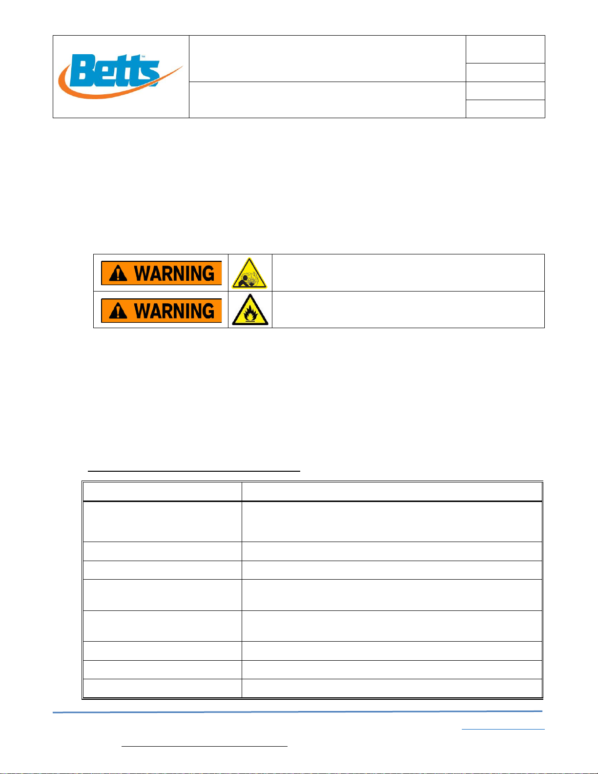
1.6 Safety alert symbols are used to alert operator to potential personal injury hazards. These symbols
are per ANSI Z535.5 and are listed below. Operator MUST obey all instructions that follow a safety
symbol. Alerts will be used to indicate known safety concerns.
A list of hazards may include but are not limited to fall hazards, pressure hazards, loaded springs,
corrosive material, flammable product, pinch points. Additional concerns are possible and should
be identified and avoided by the operator.
1.7 Product Warranty shall be void if equipment is subject to misapplication, misuse, neglect, alteration,
or damage.
1.8 Specific design details described in this document are for reference only and are subject to change
without notice. See Betts Industries, Inc. web page for the most recent revision to this document.
www.bettsind.com
1.9 WARNING: This product can expose you to chemicals including Chromium (hexavalent
compounds), which is known to the State of California to cause cancer and birth defects or other
reproductive harm. For more information go to: www.P65Warnings.ca.gov
1.10 For additional questions or more detailed technical assistance, contact the Betts Industries, Inc.
Customer Service, Sales or Engineering Department at (814) 723-1250.
Indicates an imminently hazardous situation which, if not
avoided, will result in death or serious injury.
Indicates a potentially hazardous situation which, if not
avoided, could result in death or serious injury.
Indicates a potentially hazardous situation which, if not
avoided, may result in minor or moderate injury. It may also be
used to alert against unsafe practices.

Form Title:
Document #:
INSTALLATION AND MAINTENANCE MANUAL
MM-AD005
(Form: DEF-006A-4)
Revision:
0
Document Title:
Date:
Emergency/Remote Shutdown Air Valves
Oct. 26, 2023
Page:
3 of 10
Betts Industries Inc. ▪814·723·1250 ▪1800 Pennsylvania Ave. West ▪Warren, PA 16365 ▪www.BettsInd.com
Print Date: 11/21/2023 This form is considered uncontrolled 24 hrs. after print date.
4.69
CLOSED
5.12
OPEN
1.75
1.00
1.12
.94 Ø.21
1/4" NPT
1/4" NPT
1/4" NPT
1.93
2.65
3/4-16 UNC
2.0 Parts List
No.
Description
Req.
Material
Part No.
1
Control Block
1
Anodized Aluminum
36260AA
2
Piston
1
Stainless Steel
29483SL
3
O-Ring
4
Nitrile (Buna-N)
19467BN
4
Detent O-Ring
1
Polyurethane
19507PY
5
Bushing
1
Brass
76299BR
6
Jam Nut 3/4-16
1
Stainless Steel
9Q9729
7
Flange Nut 5/16-18
1
Stainless Steel
9Q5859
8
Control Knob (Red)
1
Anodized Aluminum
76185AA-RED
9
Sticker - Shutdown
1
Vinyl
AD76276
10
End cap
1
LDPE
76327PE
1
2
5
6
10
3
3
3
3
4
8
9
7
9

Form Title:
Document #:
INSTALLATION AND MAINTENANCE MANUAL
MM-AD005
(Form: DEF-006A-4)
Revision:
0
Document Title:
Date:
Emergency/Remote Shutdown Air Valves
Oct. 26, 2023
Page:
4 of 10
Betts Industries Inc. ▪814·723·1250 ▪1800 Pennsylvania Ave. West ▪Warren, PA 16365 ▪www.BettsInd.com
Print Date: 11/21/2023 This form is considered uncontrolled 24 hrs. after print date.
3.0 Description and Intended Use
The Betts’ Emergency/Remote Shutdown Air Valve is a two position push/pull control valve. When plumbed and
mounted correctly, it fulfills the requirements of a remotely actuated means of closure per US DOT 49CFR§178.345-
11(b)(1)(i) and CSA B620-20 clause 5.6.12.3(b), (c), and (f). The Emergency/Remote Shutdown is mounted on the
end of the cargo tank farthest away from the loading/unloading outlet with normal position of the valve in the pulled-
out position and initiates shutdown function when the knob is pushed in. Please note, the Emergency/Remote
Shutdown Valve does not provide provision for thermal activation. If required, fusible plugs should be installed in-
line as needed.
The valve block is lightweight anodized aluminum. The valve includes a detent retention feature for positive click-
in feel during operation. All ports are ¼” NPT. The valve can be mounted via the through holes in the valve body
or through a Ø.81” hole in a panel and secured with the ¾“ hex nut (included).
Simplified plumbing schematics are provided below for the two most common methods of operation. A detailed
plumbing schematic is available upon request. Verify proper shutdown function once valve is installed and test
monthly during active service.
Plumbing Option 1
Emergency Shutdown provides positive air signal
Plumbing Option 2
Emergency Shutdown exhausts air system pressure
Knob pushed-in position: Positive
air signal is sent from port 2 to
compatible Air Panel or Master
Control Valve which shuts down
pneumatic valve system.
Knob pushed-in position: Port
2 exhausts air pressure from
air-lines and shuts down
pneumatic valve system.
Knob pulled-out position: Port 2
exhausts air pressure from Air
Panel or Master Control’s reset
ports and the cargo tank valve
system is now operational.
Knob pulled-out position: Port
2 supplies air pressure to
pneumatic valve system and
the cargo tank valve system is
now operational
4.0 Installation
4.1 Per US DOT 49CFR§178.345-11(b)(1)(i), the Emergency Shutdown Valve must be “located more
than 10 feet from the loading/unloading outlet where vehicle length allows, or on the end of the
cargo tank furthest away from the loading/unloading outlet.”
4.2 Per §172.328(d) “each on-vehicle manually-activated remote shutoff device for closure of the
internal self-closing stop valve must be identified by marking “Emergency Shutoff” in letters at least
0.75 inches in height, in a color that contrasts with its background, and located in an area
immediately adjacent to the means of closure.”
4.3 The valve can be mounted via the through holes in the valve body or through a Ø.81” hole in a
panel and secured with the ¾“ hex nut (included). See figures 1 and 2.
4.4 The valve should be mounted with exhaust port facing down protected from moisture. If needed,
utilize an elbow and drop tube to route the exhaust to an area free of moisture or debris.
4.5 If airline conditioner/antifreeze is used, it must be compatible with O-ring material.
Pushed
In
Pulled
Out
Pushed
In
Pulled
Out

Form Title:
Document #:
INSTALLATION AND MAINTENANCE MANUAL
MM-AD005
(Form: DEF-006A-4)
Revision:
0
Document Title:
Date:
Emergency/Remote Shutdown Air Valves
Oct. 26, 2023
Page:
5 of 10
Betts Industries Inc. ▪814·723·1250 ▪1800 Pennsylvania Ave. West ▪Warren, PA 16365 ▪www.BettsInd.com
Print Date: 11/21/2023 This form is considered uncontrolled 24 hrs. after print date.
Fig. 1: Secured with Panel Nut, and drop tube to route exhaust
Fig. 2 : Secured with Socket Head Cap Screws through body
5.0 Inspection and Testing
5.1 Bench Test
5.1.1 Inspect all components for corrosion or damage and replace if necessary.
5.1.2 Actuate the valve twice to ensure it is functioning properly with smooth operation.
Ensure that the detent bushing feature is functioning properly with click-in feel in both
open and closed positions.
5.1.3 Check and ensure the end cap is snapped into the back of the valve and ensure that
the vent hole in the cap is not plugged or blocked.
5.1.4 Apply line pressure of 90-125 psi to the ports shown in the table below and inspect for
leaks. See Disassembly and Rebuild section for needed repairs.
Exhaust elbow
drop tube
Exhaust exits at bottom

Form Title:
Document #:
INSTALLATION AND MAINTENANCE MANUAL
MM-AD005
(Form: DEF-006A-4)
Revision:
0
Document Title:
Date:
Emergency/Remote Shutdown Air Valves
Oct. 26, 2023
Page:
6 of 10
Betts Industries Inc. ▪814·723·1250 ▪1800 Pennsylvania Ave. West ▪Warren, PA 16365 ▪www.BettsInd.com
Print Date: 11/21/2023 This form is considered uncontrolled 24 hrs. after print date.
5.2 Field Testing (monthly testing)
5.2.1 Visual inspection:
5.2.1.1 Inspect exterior of valve for corrosion or damage. Pay special
attention to the area where the stem moves in and out of the bushing.
5.2.1.2 Inspect for any air leaking at any of the fittings, at the stem or end cap.
5.2.1.3 Look for leakage of fluid out of exhaust port. This could be an
indication of a seal failure in one of the Emergency Valves or Air
Manifold. Investigate and repair the problematic component.
5.2.1.4 Ensure the end cap is snapped into the back of the valve and ensure
that the vent hole in the end cap is not plugged or blocked.
5.2.1.5 Inspect exhaust port and make sure it is unobstructed and oriented in
an area that is protected from weather, debris or moisture.
Valve
Port
Valve Position
Checks
1
Valve Open
1. Port 1 blocks pressure.
2. No leakage at port 2 or 3.
3. No leakage between the End Cap and the Body or out the
hole in the End Cap.
4. No leakage between the stem and the front of the body.
1
Valve Closed
1. Port 2 expels pressure.
2. No leakage at port 3.
3. No leakage between the End Cap and the Body or out the
hole in the End Cap.
4. No leakage between the stem and the front of the body.
3
Valve Closed
1. Port 3 blocks pressure.
2. No leakage at port 1 or 2.
3. No leakage between the End Cap and the Body or out the
hole in the End Cap.
4. No leakage between the stem and the front of the body.
3
Valve Open
1. Port 2 expels pressure.
2. No leakage at port 1.
3. No leakage between the End Cap and the Body or out the
hole in the End Cap.
4. No leakage between the stem and the front of the body.
2
3
1
Air In
2
3
1
Air In
2
3
1
Air In
2
3
1
Air In

Form Title:
Document #:
INSTALLATION AND MAINTENANCE MANUAL
MM-AD005
(Form: DEF-006A-4)
Revision:
0
Document Title:
Date:
Emergency/Remote Shutdown Air Valves
Oct. 26, 2023
Page:
7 of 10
Betts Industries Inc. ▪814·723·1250 ▪1800 Pennsylvania Ave. West ▪Warren, PA 16365 ▪www.BettsInd.com
Print Date: 11/21/2023 This form is considered uncontrolled 24 hrs. after print date.
5.2.2 Operation:
5.2.2.1 Open and close the valve several times.
5.2.2.2 Feel for smooth operation with a positive “click-in” feel in both the
open and closed position.
5.2.3 Functional:
5.2.3.1 Prior to testing the function of the Emergency/Remote Shutdown
Valve make sure the cargo tank is safe to simulate a shut down.
Cargo tank and piping should be empty and all end of piping stop
valves and caps should be closed and in place.
5.2.3.2 With Emergency Valves or Air Manifold Valves open, actuate the
Emergency/Remote Shutdown Valve.
5.2.3.3 To satisfy 49CFR§178.345-11(b)(1), inspect Emergency Valves and
Air Manifold Valves to ensure they completely closed within 30
seconds of actuating the Emergency/Remote Shutdown Valve.
5.2.4 Repair or replace the Emergency/Remote Shutdown Valve if it does not meet any
of the monthly field testing requirements.
6.0 Disassembly and Rebuild Instructions
Pressure Hazard –Cargo tank or piping may contain
residual pressure and failure to safely relieve could result in
sudden loss of pressure causing death or serious injury.
Flammable Product –Cargo tank or piping may contain
product that could present risk of fire, explosion, asphyxiation
or other hazards resulting in death or serious injury.
Tools
Use
½” open ended wrench
Qty 2
Removing the control knob (8) and Flange Nut 5/16-18 (7).
O-ring Pick
Removing O-rings (3)
Small flat head screwdriver
Pop off end cap (this may not be needed)
7/32”Allen Wrench
Prevent piston from spinning to remove (7) (this may not be
needed)
Low temperature silicone
lubricant
Lubricate O-rings (3)
Arbor Press (optional)
Only needed to remove the pressed-in bushing (5)
.495 Dia X 4” Pin (optional)
Only needed to remove the pressed-in bushing (5)
Thread lock compound
Threaded connections

Form Title:
Document #:
INSTALLATION AND MAINTENANCE MANUAL
MM-AD005
(Form: DEF-006A-4)
Revision:
0
Document Title:
Date:
Emergency/Remote Shutdown Air Valves
Oct. 26, 2023
Page:
8 of 10
Betts Industries Inc. ▪814·723·1250 ▪1800 Pennsylvania Ave. West ▪Warren, PA 16365 ▪www.BettsInd.com
Print Date: 11/21/2023 This form is considered uncontrolled 24 hrs. after print date.
6.1 Disassembly
6.1.1 Use the two ½” open ended wrenches to remove the Control Knob (8) and the
Flange Nut (7) from the piston (2). If the flange nut (7) is spinning with the piston, use
a small screwdriver to pop off the end cap (10). Insert a 7/32”Allen wrench into the
end of the piston to prevent it from spinning to remove the Flange Nut (7).
6.1.2 Push the piston (2) through the back of the valve. If the end cap (10) is still on, apply
enough force to pop the end cap and piston out through the back of the valve.
6.1.3 Remove the O-rings (3) from the piston. Using your fingers, squeeze the O-rings (3)
up to be able to slide a plastic O-ring pick under the O-ring and pull it off the piston.
Do not use a sharp pick which may scratch or damage the O-ring grooves on the
piston. The polyurethane detent O-ring (4) is a split O-ring and can easily be pulled
off the piston. Discard the used O-rings.
6.1.4 Clean and inspect the piston (2). Replace if there is any wear or damage.
6.1.5 Clean and inspect the control block (1) bore. Replace if there is any wear, corrosion,
or damage.
6.1.6 Inspect the bushing (5) for corrosion or damage. If it needs replaced, use the .495
diameter pin and push out the bushing (5) using an arbor press.
6.2 Rebuild
6.2.1 If the Bushing (5) was removed, it must be pressed into the Control Block (1) using
an arbor press. Retaining compound is recommended but do not get compound in
the bore of the bushing (5) and clean off all excess compound after assembly.
Ensure that the bushing (5) starts straight and presses flush with the thread face of
the control block (1).
6.2.2 The Detent O-ring (4) is a white polyurethane O-ring. Use a razor blade and cut the
O-ring in one spot. The cut location is not critical.
6.2.3 Install the split Detent O-ring (4) onto the Piston (2) in
the location as shown in Fig. 3.
6.2.4 Install the other O-rings (4) onto the Piston (2) in the
locations as shown in Fig. 3.
6.2.5 Lubricate all O-rings (3) using low temperature silicone
lubricant. Ensure that O-rings are compatible with any
airline conditioner/antifreeze.
6.2.6 Insert the piston (2) with all O-rings into the Control
Block (1). Be careful when inserting the piston to
prevent any O-ring damage.
6.2.7 If attaching to a panel, insert the Control Block into the panel and thread on the panel
Jam Nut (6). Apply thread lock compound to the threads to prevent vibration from
loosening the nut.
6.2.8 Apply thread lock compound to the piston threads and thread on the Flange nut (7)
until it bottoms out on the piston (2). Thread the control knob (8) down to the flange
Fig. 3

Form Title:
Document #:
INSTALLATION AND MAINTENANCE MANUAL
MM-AD005
(Form: DEF-006A-4)
Revision:
0
Document Title:
Date:
Emergency/Remote Shutdown Air Valves
Oct. 26, 2023
Page:
9 of 10
Betts Industries Inc. ▪814·723·1250 ▪1800 Pennsylvania Ave. West ▪Warren, PA 16365 ▪www.BettsInd.com
Print Date: 11/21/2023 This form is considered uncontrolled 24 hrs. after print date.
nut. Using two 1/2” open ended wrenches, tighten the flange nut (7) into the control
knob (8).
6.2.9 Insert the end cap (10) into the Control Block (1).
6.2.10 Test the rebuilt Emergency/Remote Shutdown Valve for proper function per 5.1
Bench Test Procedure prior to installation. Verify proper shutdown function once
installed.
7.0 Troubleshooting Guide
Use to help diagnose potential issues that could be encountered. The list is not all inclusive and other solutions might be needed.
Problem
Potential Cause
Potential Solution
When actuated, the
Emergency/Remote
Shutdown Valve does
not shutdown the
loading/unloading
outlets (emergency
valves).
Emergency/Remote Shutdown Valve is not
plumbed correctly.
Verify the plumbing is correct depending on how
the air system on the cargo tank is designed.
See schematic in section 3.0.
Exhaust port of Emergency/Remote Shutdown
Valve is plugged.
Clear exhaust port.
Airline to Emergency/Remote Shutdown Valve
is not getting air pressure.
Resolve air feed issue.
Airline from Emergency/Remote Shutdown
Valve is damaged, plugged or pinched.
Replace damaged airline.
Master Control Valve on Air Panel is not
operating properly.
Resolve Master Control Valve or Air Panel issue.
Emergency/Remote Shutdown Valve is not
operating properly.
Review entirety of troubleshooting guide and
replace or rebuild Emergency/Remote Shutdown
Valve as necessary.
Valve stuck open or
closed. Hard to
actuate.
Corroded bushing (5) or control block (1).
Investigate reason for corrosion. Harsh cleaning
solutions or incompatible airline additives should
not be used. Remove and replace bushing (5).
If the bore of the control block (1) is corroded it
is recommended to replace the entire valve.
Damaged or bent piston (2).
Replace piston (2) but also inspect bore of
bushing (5) and control block (1) to see if they
are also damaged.
O-rings (3) swelled.
Investigate reason for O-Ring swelling.
Incompatible airline additives should not be
used. Product may be leaking into airline from
one of the Emergency Valves or Air Manifold.
See specific problem below: Product of cargo
tank leaking from exhaust port (liquid/fumes).
O-rings (3) damaged.
Investigate reason for O-rings (3) damage.
Burrs or sharp edges inside bore should be
removed without damaging sealing surface prior
to replacing O-rings (3).
Ice or debris behind end cap (10) or in valve.
Remove ice or debris. Replace end cap (10)
with a new cap. Ensure the exhaust port is
facing down protected from moisture.
Continued on next page.

Form Title:
Document #:
INSTALLATION AND MAINTENANCE MANUAL
MM-AD005
(Form: DEF-006A-4)
Revision:
0
Document Title:
Date:
Emergency/Remote Shutdown Air Valves
Oct. 26, 2023
Page:
10 of 10
Betts Industries Inc. ▪814·723·1250 ▪1800 Pennsylvania Ave. West ▪Warren, PA 16365 ▪www.BettsInd.com
Print Date: 11/21/2023 This form is considered uncontrolled 24 hrs. after print date.
Problem
Potential Cause
Potential Solution
Air leak from valve.
O-rings (3) swelled.
Investigate reason for O-Ring swelling.
Incompatible airline additives should not be
used. Product may be leaking into airline from
one of the Emergency Valves or Air Manifold.
See specific problem below: Product of cargo
tank leaking from exhaust port (liquid/fumes).
O-rings (3) damaged.
Investigate reason for O-rings (3) damage.
Burrs or sharp edges inside bore should be
removed without damaging sealing surface prior
to replacing O-rings (3).
Bore of control block (1) damaged or dirty.
Clean and inspect bore of control block (1). If
bore is damaged replace the entire valve.
O-ring grooves on piston (2) scratched or dirty.
Clean and inspect piston (2). If piston (2) is
damaged replace piston (2).
Bushing (5) has partially pulled out.
Remove and discard bushing (5). Replace
bushing following step 6.2.1.
Flange nut (7) is not threaded down to
shoulder of piston.
Apply thread lock compound to the threads of
the piston (2). Remove end cap (10) and hold
piston (2) stationary with Allen wrench. Tighten
flange nut (7) down to the shoulder of the piston
(2). Tighten the Control knob (8) to the flange
nut and lock together.
Product of cargo tank
leaking from exhaust
port. (liquid/fumes)
This could be an indication of a seal failure in
one of the Emergency Valves or Air Manifold.
Investigate and repair the problematic
component of Emergency Valve or Air Manifold.
Flush and dry all airlines.
The Emergency/Remote Shutdown Valve should
be taken apart, cleaned and O-rings (3) replaced
prior to placing back in service.
Detent is not providing
a positive “click-in” feel
in both the open and
closed position.
Detent O-ring (4) is worn.
Replace with new detent O-ring (4). Please
note, this O-ring is a split polyurethane O-ring.
Flammable Product - Cargo tank, piping
or air system may contain product that
could present risk of fire, explosion,
asphyxiation or other hazards resulting in
death or serious injury.
Table of contents
Other Betts Control Unit manuals
Popular Control Unit manuals by other brands

Immergas
Immergas MAGIS PRO ERP Instruction and recommendation booklet

Pentair
Pentair HI-FLOW 261049 Installation and user guide

Rockwell Automation
Rockwell Automation Allen-Bradley Micro800 manual

Madas
Madas XVR-1-3-6 manual

Gi
Gi MP48 DF installation manual

Baldor
Baldor 23H Series Installation & operating manual

XQP
XQP 500 Series manual

Siemens
Siemens SENTRON product manual

vacuubrand
vacuubrand VAC 24seven Instructions for use

Grundfos
Grundfos CIM 1 Series Installation and operating instructions

Zurn Wilkins
Zurn Wilkins 375 Installation, Testing, Maintenance Instructions

Miele
Miele DSM 408 Operating and installation instructions