Beyond SONANCE INVISIBLE Series User manual

INVISIBLE SERIES IS15W SUBWOOFER
INSTALLATION MANUAL

2
IMPORTANT SAFETY INSTRUCTIONS
This product is intended to be installed by professional
AV integrators and installers only. This product manual
is intended to serve as a general guideline for most
applications. It is the installer’s responsibility to ensure
this product is installed in accordance with local
building codes and regulations. Consult a local authority
for specific requirements, regulations, and building
codes of the jurisdiction in which this product is to be
installed.
READ THIS DOCUMENT IN ITS
ENTIRETY BEFORE ATTEMPTING USE.
1. Read these instructions.
2. Keep these instructions.
3. Heed all warnings.
4. Follow all instructions.
5. Clean only with a dry cloth.
6. Do not block any ventilation openings. Install in
accordance with the manufacturer’s instructions.
7. Do not install near a heat source such as radiators,
heat registers, stoves, fireplaces, or other apparatus
(including amplifiers) that produce heat.
8. Only use attachments/accessories specified by
Sonance.
9. Refer all servicing to qualified service personnel.
BOX CONTENTS
(1) Invisible Speaker with Cutout Template
(2) Wire Nuts
(28) Stainless Steel Screws
(4) 1/16” (1.6mm) Shims
(4) 1/8” (3.18mm) Shims
INVISIBLE SERIES SUBWOOFER
IS15W
TABLE OF CONTENTS
2 Important Safety Instructions & Box Contents
3 Product Description & Features
4 Product Preparation & Planning
5 Project Management
6 Example Checklist
7 Installation - Framing Detail
8 Installation - Drywall Detail
9 Finish Guidelines
10 Finishing Instructions
13 Technical Specifications
14 FAQ
15 Technical Assistance & Service
16 Warranty
Scan QR code for installation video.
For technical support call (949) 492-7777 or visit
www.sonance.com/in-wall-in-ceiling/invisible-series
FRONT BACK

3
PRODUCT DESCRIPTION
The Sonance Invisible Series IS15W Subwoofer
features Motion Flex Technology oering a suite of
advancements in speaker engineering that delivers
unparalleled acoustic performance and installation
enhancements that allow a wider range of applications
with more consistent results. Together these
performance and installation improvements redefine
what is possible from an invisible subwoofer.
This line of full-range speakers and woofers incorporate
Wave Flex drive units, carbon fiber Air Flex woofers,
and acoustically-isolated baes, allowing for up to 180
degrees of smooth o-axis response.
The innovative Sonance DISC System enables non-
destructive measurement of the finish thickness for
consistent and repeatable installation results.
Sonance DSP amplifier presets should be used to
maximize the performance of any Invisible Series
system.
FEATURES
• Compatible with 1/2” (12.5mm) & 5/8” (15mm)
drywall using included shims. Supply your own
shims for thicker substrates.
• Finish-up-to or finish-over with up to 1/16” (1.5mm)
flexible topping compound or finish material.
• 180 degree hemispherical dispersion (IS15W)
• Embedded depth discs allow the installer to verify
the finish material thickness with the optional DG-1
DISC System Depth Gauge (SKU 93491)
• The IS15W sound-isolating enclosure provides up
to 20dB reduction of sound transferred to adjacent
spaces.
• The IS15W is protected by integrated poly fuses
which protect the transducer from over-current.
• 15 year limited warranty.
Mounting points for
attachment to framing.
FRONT
BACK
SIDE
Paper facing to ensure
finishes over the speaker and
surrounding drywall dry at the
same rate.
0.02” (0.5mm) beveled edge
allows for seamless joints.
Sonance DISC system. Four
steel discs embedded behind
the speaker diaphragm for
accurate finish thickness
measurement.
12” (305mm) speaker lead.

4
PRODUCT PREPARATION
Amplifier Selection
The IS15W subwoofer requires a Sonance DSP 2-750
Amplifier in order to ensure high performance, to
protect the speaker and installation, and to achieve
consistent results. Sonance DSP Amplifiers are rated
down to 4 Ohms and are stable to 2 Ohms. Never run
more than two IS15W subwoofers in parallel on one
amplifier channel.
Wire Gauge - 8 ohm Systems
When using the product in an 8 Ohm (low impedance)
system, the total wire resistance should be less than 10%
of the speaker impedance. The speakers are nominally
6 Ohms impedance, so your total wire resistance should
be no more than 0.6 Ohms. In simple terms, the extra
resistance from the wire will have a very negative aect
on the sound quality of the speaker. The sound can
be less dynamic, definition of bass frequencies can be
reduced, and in extreme cases, the high frequencies can
be attenuated. Amplifier power is also wasted in the
wire, reducing the maximum output level of the system.
Please refer to the chart below when deciding on the
appropriate wire gauge for your installation.
SPEAKER LOCATIONS
Invisible Series full-range speaker models (IS6, IS8, IS10)
have a 170 degree hemispherical dispersion pattern.
The IS15W subwoofer has a 180 degree hemispherical
dispersion pattern. This allows for a wide range of
applications and installation locations.
IMPORTANT: The IS15W should only be wall mounted.
Ceiling placement could lead to long term sagging of
the diaphragm.
The 1S15W should only be wall mounted. Ensure that the
speaker will not be covered by cabinetry, draperies, art,
crown molding or anything that could cover or puncture
the speaker. Ensure that the back of the speaker has
clearance and will not be adjacent to other building
systems such as electrical, HVAC, pipes, fire sprinklers
or others that could violate local building codes or
adversely eect sound quality.
WIRE RESISTANCE IN OHMS VS. LENGTH OF CABLE RUN
DISTANCE 50’
15.2m
100’
30.5m
150’
45.7m
200’
61m
250’
76.2m
300’
91.4m
20 GAUGE 0.86 1.73 2.59 3.45 4.32 5.18
18 GAUGE 0.65 1.30 1.94 2.59 3.24 3.89
16 GAUGE 0.43 0.85 1.28 1.71 2.14 2.56
14 GAUGE 0.27 0.54 0.81 1.08 1.35 1.62
12 GAUGE 0.17 0.34 0.51 0.68 0.85 1.02
INSTALLATION ACCESSORIES
The use of space savers and preconstruction zip
rings will assist in better coordination of trades and
is recommended for the best result. Space savers are
a great way to reserve the precise dimensions and
location of your Sonance Invisible Series speakers
during the construction phase and will protect your
speaker wire from getting lost within the wall or ceiling
cavities. The space saver allows you to delay the
installation of the actual invisible speaker to just prior
to the finishing stage. This reduces the risk of damage
or theft of speakers on the job site. If your project calls
for large quantities of invisible speakers, you may use
our preconstruction zip ring brackets as an easy guide
for getting the perfect drywall cutout using a drywall
zip tool. These can be installed in conjunction with the
space savers or on their own and are to be used when
drywall will be laid up directly over speaker locations.
Zip rings are made-to-order, so please contact your
Sonance representative for bulk pricing and availability.
NEW CONSTRUCTION
The subwoofer will occupy two stud bays in a standard
16” on center framed wall. The subwoofer should be
boxed out much like a window. Structural loads must
be transferred from the top plate to the bottom plate,
while allowing room for the speaker. See the diagram
below as a general recommendation. Note the following
best practices:
1. Use the speaker template to create the proper
space for the subwoofer.
2. Two scabs are added to the header. The gap in
between the two scabs provides space for the
speaker wire strain relief. If the speaker wire is
coming from below, then the scabs will be added to
the sill.
3. Construction adhesive must be used to bond all the
double studs together. This helps prevent creaking
and buzzing.
4. Screws should be used instead of nails for the
subwoofer location as nails can loosen over time.
Installing the Speaker
These are key tips for installing the subwoofer.
• Do not remove the back box of the subwoofer.
• Install the speaker with the included stainless-steel
screws.
• Do not add a screw at the center location above the
speaker wire strain relief. Wire damage can occur
SPACE SAVER PART NUMBERS
IS-SAVER-S IS6 93492 4-pack
IS-SAVER-M IS8/IS8T/IS10W 93493 4-pack
IS-SAVER-L IS10 93494 4-pack
IS-SAVER-XL IS15W 93495 Each

5
PROJECT MANAGEMENT
Follow the installation instructions in this manual
precisely to ensure outstanding speaker performance
and true invisibility. To accomplish this flawlessly
every time requires project management and close
coordination with the drywall and finish trades along
with the General Contractor and sometimes even the
client. Here are some best practices that will prevent
unmet expectations and expensive rework:
• After IS speakers are connected and screwed in but
before any drywall mudding, taping, or finishing
has started, schedule a walk-through with the client
from the screw.
Listening Test
These are key tips for testing the subwoofer.
• Allow construction adhesive to dry before
energizing the subwoofer.
• During listening testing prior to mudding, listen for
buzzes, squeaks, and chung.
• Fix noise problems before drywall mud is applied.
• Let the subwoofer play at a moderate to high
level for 30 minutes to allow possible noises to be
discovered.
Drywall
The stud bays above and below the subwoofer cutout
as well as the stud bays on either side of the subwoofer
cutout should have construction adhesive added to
front and back of studs when attaching drywall. Drywall
can loosen over time and create buzzing and slapping
noises. In addition to the construction adhesive, screws
must be used instead of nails. Screws should be placed
every four inches around the subwoofer opening and
every six inches for the stud bays on either side of the
subwoofer cutout. Do not have a drywall joint at the
IS15W location. Use studs to support any drywall joint
near the IS15W. Place construction adhesive on the
bottom plate as well to prevent air leaks and chung
sounds.
FINISH MATERIALS
Prior to speaker installation, verify that the topping
compound and final finish are flexible materials (slow-
setting drywall mud/topping compound, wallpaper,
acrylic-based Venetian plaster, thin wood veneer) and
will not exceed 1/16” (1.5mm).
Our recommended target for optimal performance
is between 3/64”-1/16” (1.0-1.5mm) of topping
compound. Sound quality and installation durability
will be adversely eected if too much topping
compound is applied. For wood veneer finishes, use
only 20mil (0.5mm) veneer with paper backing.
Do not use hard-setting or sti materials over the
surface of invisible speakers, such as fast-setting
drywall mud (“hot mud”), genuine Venetian plaster,
stucco, metal panels, tile, etc.
(or client’s representative), the General Contractor,
and the finish manager. Listen to every speaker
for a couple minutes. This is the best opportunity
to discover any anomalies or issues with invisible
speaker performance.
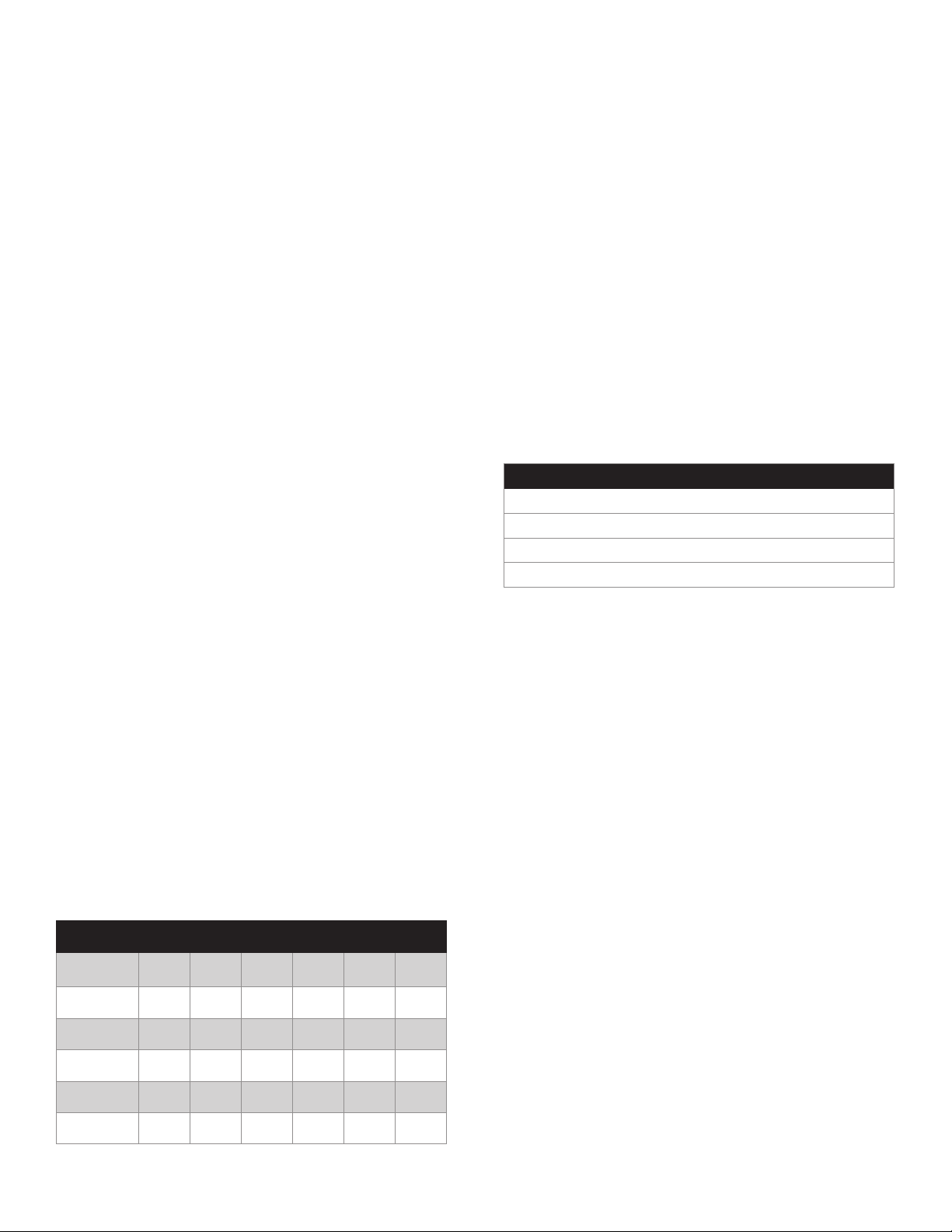
• All in attendance should sign o on audio
performance, speaker-by-speaker and room-by-
room. Prepare a checklist like the example below
and ask all parties to sign and date, acknowledging
that the Sonance IS speakers perform to everyone’s
expectations.
• Review all installation steps and processes with the
finish manager, emphasizing to cover the speakers
with only enough flexible material to make the
speakers disappear and no more. This typically ends
up being our recommended target of 3/64”-1/16”
(1.0-1.5mm). Also emphasize the maximum of 1/6”
(1.5mm) finish thickness. Review our guidelines for
recommended materials on page 4 and 14 with the
finish manager. Construction adhesive must be used
between drywall and studs.
• Use the Sonance DISC system and DG-1 depth
gauge (SKU 93491) to validate the finish thickness.
It is helpful to lend the gauge to the finish manager
so that it can be used during the actual process.
• Once the finish material has completely dried,
perform another room-by-room listening check of
each speaker. If the speakers do not sound similar
to the performance you heard prior to finishing,
it is likely that the finish thickness exceeds the
maximum of 1/16” (1.5mm). Now is the time to
correct this by removing material.
• Remember: once the flooring is installed and the
furniture is in place, it is too late to remove excess
finish material from the Sonance IS speakers
without significant cost, cleanup, and/or complexity.
Eective project management, sign-os, and proactive
communication with the trades will prevent unexpected
results and provide consistent, beautiful installs that
wow the client and end-users.
ADDITIONAL INFORMATION
For CAD files, detailed dimensions, and other technical
information, scan the QR code below or visit
www.sonance.com/in-wall-in-ceiling/invisible-series

6
SONANCE INVISIBLE SPEAKERS AUDIO PERFORMANCE SIGN-OFF CHECKLIST
PROJECT NAME ______________________ ROOM # ____ ROOM DESCRIPTION ___________________________________________
Model Serial # PRE-Finishing
Audio Test Approval
Measured Finish
Thickness
POST-Finishing
Audio Test Approval
Speaker 1 ¨mm ¨
Speaker 2 ¨mm ¨
Speaker 3 ¨mm ¨
Speaker 4 ¨mm ¨
Speaker 5 ¨mm ¨
Speaker 6 ¨mm ¨
Audio Test Approval Signatures:
Date:
EXAMPLE CHECKLIST:

7
INSTALLATION - FRAMING DETAIL
BEST PRACTICE: Use screws
and construction adhesive
between studs.
IMPORTANT: Due to the high
output and forces that are
generated by this subwoofer,
the wall construction and
drywall application are critical
elements of this installation
process. Attention to the details
described in this manual will
help ensure the best possible
product installation.
IMPORTANT: The IS15W should only
be wall mounted. Ceiling placement
could lead to long term sagging of
the diaphragm.

8
INSTALLATION - DRYWALL DETAIL
Place stud behind any drywall joints.
No joints next to speaker.
IMPORTANT: Must use construction
adhesive under drywall.
Screw every
6” (152mm)
Screw every
4” (102mm)

9
PRE-FINISHING TESTING
GUIDELINES
Once a finish is applied to an invisible speaker, it will
be too late to go back and fix any audio connection
or installation problems.
Installation Fit Test
Lightly place a straight edge across the face of the
speaker to verify that the diaphragm of the speaker
is co-planar with the surrounding drywall and has
been installed correctly. Adjust shims if necessary. It
is normal for the beveled edge of the speaker to be
recessed from adjacent drywall.
Audio Test
Connect a high-quality audio source and Sonance
DSP-2-750 amplifier (in 8 Ohm mode) to the
installed IS15W subwoofer. Ensure the correct EQ
preset is applied using SonArc software. Adjust
the output for a moderate volume level consistent
with how the speakers will be used in the space.
Play music to check for overall fidelity and listen
for any buzzes or rattles. We also recommend
a slow tone sweep from 20Hz to 500Hz for
subwoofers and 20Hz to 5kHz for full-range
speakers to help pinpoint any buzzing that could
be caused from loose studs/screws/drywall, cable
vibration, or rattling of outlets, lighting components,
construction fixtures, etc.
Fix any installation or audio issues before moving
on to the next steps.
We highly recommend active project management
practices as described on page 5-6. Only after
passing these testing guidelines should you
proceed to the finishing stage.
IS15W FINISH THICKNESS
GUIDELINES
Sound quality and installation durability will be
adversely eected if finish materials are applied too
thick.
TOTAL FINISH THICKNESS FOR OPTIMAL
PERFORMANCE OF IS15W SUBWOOFER:
Apply the absolute minimum finish necessary to
make the speaker totally invisible. Typically 3/64”
(1.0mm) or less.
MAXIMUM TOTAL FINISH THICKNESS
FOR IS15W SUBWOOFER:
1/16” (1.5mm)
Validate finish thickness using the Sonance DG-1
depth gauge (SKU 93491).
Do not use hard-setting or sti materials over the
surface of invisible speakers, such as fast-setting
drywall mud (“hot mud”), genuine Venetian plaster,
stucco, metal panels, tile, etc. Use only flexible
materials to finish invisible speakers such as
lightweight drywall topping compound.
When using flexible sheet materials such as
wallpaper or veneer, ensure that the total thickness
of any drywall compound, adhesives, and the
finishing substrate itself does not exceed 1/16”
(1.5mm). For wood veneer finishes, use only 20mil
(0.5mm) veneer with paper backing.

10
FINISHING INSTRUCTIONS
NOTE: Drywall finishes can range in various levels of
smoothness. For invisible speaker installations, we
recommend at least a level four finish where drywall
seams are all feathered out and sanded. For best
results, we recommend a level five finish where
the entire wall plane is skim-coated and sanded for
smooth consistency.
1. Fill the gap between speaker and drywall with 20
minute fast-setting joint compound (“hot mud”).
2. Feather all edges.
3. Allow hot mud to set slightly before applying mesh
tape.
4. Place mesh tape over the drywall seams. Overlap
tape slightly.
5. Do not tape over the raised portion of the speaker.
6. Allow hot mud to fully cure and harden.

11
7. Once hot mud has fully cured, cover joints with
slow-setting compound.
RECOMMENDED DRYWALL COMPOUNDS
STEP 1
Filling gaps
20-minute All-Purpose Joint
Compound (“Hot Mud”)
STEP 7
Covering joints
Slow-setting Lightweight All-
Purpose Joint Compound
STEP 10, 14
Covering the speaker
Slow-setting Lightweight Easy-
Sand Topping Compound
NOTE: DO NOT use fast-setting drywall compound
(“hot mud”) to cover the speaker; it is not flexible
enough to provide a durable finish for invisible
speakers. Instead we recommend a lightweight all-
purpose joint compound to cover joints and feather up
to the surface of the speaker. Lightweight, easy-sand
topping compound should be used for covering the
speaker.
IMPORTANT: If a perfectly flat finish is achieved at
this point, you may opt to proceed to the priming and
painting phase. This is what we refer to as a “Finish Up
To” installation. In this case, we recommend multiple
layers of paint to achieve a shadow-less, even blending
of color.
We highly recommend a “Finish Over” process where
an additional skim coat is applied over the entire
speaker and blended into the surrounding wall plane.
A Finish Over process typically takes less time to
complete versus Finish Up To because fewer layers
of paint are needed. And with the skim coat over the
entire surface of the speaker and wall, it’s much easier
to achieve perfect invisibility.
8. Feather all surfaces around the joints and up to the
raised portion of the speaker diaphragm.
9. Allow first coat to fully cure. This can take 12–24
hours.
10. Apply a second coat of topping compound covering
the entire surface of the speaker and all adjoining
surfaces.

12
11. Compound buildup on the active surface of the
speaker should not exceed 1/16” (1.5mm).
12. Detail the compound to minimize tool marks.
13. Allow each layer to fully cure. This can take 12–24
hours.
14. Build more coats as necessary to achieve desired
finish. Each successive coat should be thinner than
the last. The final coat should be a very light skim
coat application.
15. After final coat is applied and has dried, use a
manual pole sander or block sander on entire wall
(do not use a power sander as this could damage
the surface of the speaker). Be careful not to sand
down into the surface of the speaker. This could
damage the paper which makes perfect blending
very dicult to achieve. Wall surface should show
no signs of a speaker.
16. Validate the finish thickness using the Sonance DISC
system and DG-1 depth gauge (SKU 93491).
17. The final step is to once again perform an audio
test. Listen to each speaker and verify that audio
quality and performance have not significantly
changed since your initial listening test just prior to
the finishing stage. Now is the best time to fix any
audible anomalies or surface imperfections.
After listening validation, your Sonance Invisible
speaker installation is now complete. From this
point, follow your normal method for final finishing
with flexible materials such as paint, wallpaper,
veneer, and so on.

13
SPECIFICATIONS IS15W
SUBWOOFER
SKU 93482
Air Flex
Woofer
592in²(3819cm²) air pulse diaphragm
15" (381mm) carbon fiber woofer
Frequency Response
(±3dB) 30Hz–250Hz
Nominal Impedance
(Ohms) 6
Power Handling (RMS) 250W
Sensitivity (2.83V/1m) 93dB
Dispersion 180º hemispherical
Overload Protection One self-resetting poly switch
Product Dimensions
(WxHxD)
32.2” x 32.2” x 3.86”
(818mm x 818mm x 98mm)
Mounting Depth 3.39" (86mm)
Shipping Weight 72.3lbs (32.8kg) /Each
TECHINCAL SPECFICATIONS

14
FREQUENTLY ASKED QUESTIONS
The IS15W should not be mounted in T-Bar ceilings.
Ceiling placement could lead to long term sagging of
the diaphragm.
Can these be used outside?
Sonance invisible speakers are not outdoor rated and
should not be used outside.
Can these be used in high heat or high humidity
applications?
Invisible speakers should not be directly exposed
to high heat or humidity. However you may use
finishing materials that are rated for high heat and
humidity exposure, provided that they form a barrier
that prevents exposure to the speakers. We highly
recommend you perform a mock-up trial of the finish
materials, speaker, and environment to validate the
performance long-term.
What finish materials can I use with invisible speakers?
Can these be covered with wallpaper or wood veneer?
Use flexible materials such as: slow-setting, lightweight
drywall compounds, wallpaper, wood veneer, vinyl
veneer, acrylic-based venetian plaster.
Are there materials that should not be used to cover
the speakers?
Any material that is sti, inflexible, or exceeds 1/16”
(1.5mm) in total thickness over the speaker diaphragm
such as tile, metal sheet, stone veneer, true Venetian
plaster, stucco, etc. These are not compatible with
invisible speakers. The stiness of materials like these
restrict movement and result in lack of bass and mued
sound.
How much finish material can go over the speaker?
We recommend 1.0mm to 1.5mm for optimal
performance. The maximum limit is 1/16” (1.5mm).
How can I tell how much finish material is covering the
speaker?
Use the Sonance DG-1 depth gauge (SKU 93491) to
measure actual finish thickness covering Sonance
invisible speakers.
What is the DISC system?
The Sonance DISC System provides a highly accurate
method for non-destructively quantifying the thickness
of a finish applied on top of a Sonance invisible speaker
diaphragm. The Sonance DG-1 handheld depth gauge
uses a magnetic sensor to measure the distance
between the top of the finished speaker and steel
discs embedded in all four corners behind the speaker
diaphragm of Sonance Motion Flex Invisible Speakers.
What if I add too much finish material?
Prior to the final finishing stage (such as painting),
sand down the wall or ceiling surface and measure the
finish thickness using the DG-1 depth gauge. Repeat
as necessary until you measure 1.5mm or less. We
recommend 1.0mm and 1.5mm for optimal performance.
Is there a benefit to “Finish Up To” rather than “Finish
Over”?
There is no practical benefit to a Finish Up To style
finish. In fact, we recommend Finish Over because it
typically takes less installation time and results in a
more seamless, shadowless final finish. Furthermore, the
IS15W is optimized for about 1.0mm to 1.5mm of finish
material for best performance.
What happens if the mud or finish cracks?
Mud/finish cracks are indicative of either an improperly
applied finish or invisible speakers that have been
regularly overdriven. Though the integrated poly fuses
mitigate against damage, they cannot protect against
every type of abuse. Remember, just like traditional
speakers, invisible speakers have their limit. However,
the dierence is when a traditional speaker fails due to
over-exertion, only the speaker is damaged; whereas
with invisibles, the finish can sometimes be damaged as
well.
Though it is rare, if a crack occurs, Sonance will help
troubleshoot the issue on a case-by-case basis. We
typically start by inspecting the finish process. In most
cases, the finish was applied too thick (outside of our
specifications). With our new DISC system, we have
the ability to prevent these types of failures before
they even happen by identifying and correcting at the
installation phase. This is why we highly recommend
taking advantage of the DISC system during installation
to prevent problems down the road.
Can I use other than Sonance DSP amplifiers?
To achieve the specified performance from the IS15W
it must be used with the DSP2-750 amplifier and the
correct EQ preset. If the IS15W is used with any other
amplifier, the performance and long term reliability
could be compromised.
Are these suitable for surround sound?
The IS15W has been designed specifically for use in
surround sound and large space distributed audio
systems.
What’s the benefit of Sound-Isolating enclosures?
The integral IS15W sound-isolating enclosure provides
an impressive broadband noise reduction of about
20dB which greatly reduces sound transference into
adjacent spaces.
Is the IS15W Sound-Isolating Enclosure UL Rated?
No.
I lost the screws. What is the spec or do I have to buy
them from Sonance?
Use stainless steel #6 drywall screws in the appropriate
length depending upon drywall/installation substrate
panel thickness and local codes.
I lost the shims. How can I get more? Do I have to buy
them from Sonance?
Use standard drywall shims available from your local
hardware store.

15
Is there a protection circuit built into the speaker or
do they need to be added?
The IS15W subwoofer has a single poly fuse. If a
speaker is overdriven, one or both of the poly fuses
will trip, and the transducers will cease to make sound
which protects both the driver and the installation
surface from damage in overdrive conditions. After a
few minutes, the fuses will reset, and the speakers will
perform as normal. If the poly fuses are tripping, that’s
a sign that the speakers are being overdriven, and you
should decrease the volume. If you want more volume,
add additional invisible speakers to your space.
What is the warranty on IS invisible speakers, and
what does the warranty cover?
The 15 Year limited warranty covers the cost to replace
the speaker(s) and refinishing up to level 5 drywall
finish.
TECHNICAL ASSISTANCE AND
SERVICE
The Technical Assistance Department at Sonance is
available at (949) 492-7777 to answer any questions
concerning the operation and installation of your
speakers between the hours of 7:00 AM and 5:00 PM
Pacific time, Monday through Friday, except holidays.
In the event your unit should need repair or service, you
may return the unit to your authorized dealer or use the
following guidelines:
PLEASE KEEP ORIGINAL PACKAGING WHEN
POSSIBLE.
1. Be prepared to state the model number and / or
serial number, date of purchase, and dealer’s name
and address when calling.
2. Contact Sonance directly at (949) 492-7777 or
at www.sonance.com. YOU MUST HAVE PRIOR
AUTHORIZATION TO RETURN YOUR UNIT.
3. If you are returning the product directly to Sonance,
call us to obtain a return authorization number
(RMA) before shipping.
4. Ship the product via United Parcel Service, Federal
Express, or other package delivery service. Please
do not use the U.S. Postal Service.
5. Include the return authorization number on the
shipping label. Please do not write the RMA number
directly on the carton.
6. Ship to:
Attn: Quality Assurance Department
RMA# (include RMA number here)
Sonance
11016 Mulberry Ave. Suite B
Fontana, CA 92337

16
LIMITED FIFTEEN (15) YEAR WARRANTY
Sonance warrants to the first end-user purchaser that this Sonance-brand product (“Product”), when purchased from
an authorized Sonance Dealer/Distributor, will be free from defective workmanship and materials for the period stated
below. Sonance will at its option and expense during the warranty period, either repair the defect or replace the Product
with a new or re-manufactured Product or a reasonable equivalent.
EXCLUSIONS
TO THE EXTENT PERMITTED BY LAW, THE WARRANTY SET FORTH ABOVE IS IN LIEU OF, AND EXCLUSIVE OF,
ALL OTHER WARRANTIES, EXPRESS OR IMPLIED, AND IS THE SOLE AND EXCLUSIVE WARRANTY PROVIDED
BY SONANCE. ALL OTHER EXPRESS AND IMPLIED WARRANTIES, INCLUDING THE IMPLIED WARRANTIES OF
MERCHANTABILITY, IMPLIED WARRANTY OF FITNESS FOR USE, AND IMPLIED WARRANTY OF FITNESS FOR A
PARTICULAR PURPOSE ARE SPECIFICALLY EXCLUDED.
No one is authorized to make or modify any warranties on behalf of Sonance. The warranty stated above is the sole and
exclusive remedy, and Sonance’s performance shall constitute full and final satisfaction of all obligations, liabilities, and
claims with respect to the Product.
IN ANY EVENT, SONANCE SHALL NOT BE LIABLE FOR CONSEQUENTIAL, INCIDENTAL, ECONOMIC, PROPERTY,
BODILY INJURY, OR PERSONAL INJURY DAMAGES ARISING FROM THE PRODUCT, ANY BREACH OF THIS WARRANTY,
OR OTHERWISE.
This warranty statement gives you specific legal rights, and you may have other rights which vary from state to state.
Some states do not allow the exclusion of implied warranties or limitations of remedies, so the above exclusions and
limitations may not apply. If your state does not allow disclaimer of implied warranties, the duration of such implied
warranties is limited to period of Sonance’s express warranty. Your Product Model and Description: IS6/IS8/IS10/IS10W
Invisible Speakers. Warranty Period for this Product: Fifteen (15) years from the date on the original sales receipt or
invoice or other satisfactory proof of purchase. Additional Limitations and Exclusions from Warranty Coverage: The
warranty described above is nontransferable, applies only to the initial installation of the Product, does not include
installation of any repaired or replaced Product, does not include damage to allied or associated equipment which
may result for any reason from use with this Product, and does not include labor or parts caused by accident, disaster,
negligence, improper installation, misuse (e.g. overdriving the amplifier or speaker, excessive heat, cold or humidity,
mishandling, etc.), or from service or repair which has not been authorized by Sonance. Obtaining Authorized Service:
To qualify for the warranty, you must contact your authorized Sonance Dealer/Installer or call Sonance Customer Service
at (949) 492-7777 within the warranty period, must obtain a return merchandise number (RMA), and must deliver the
Product to Sonance shipping prepaid during the warranty period, together with the original sales receipt, or invoice or
other satisfactory proof of purchase.
©2021 Sonance. All rights reserved. Sonance is a registered trademarks of Dana Innovations. Due to continuous product improvement,
all features and specifications are subject to change without notice. For the latest Sonance product specification information visit our
website: www.sonance.com
SONANCE • 991 Calle Amanecer • San Clemente, CA 92673 USA
PHONE: (949) 492-7777 • FAX: (949) 361-5151 • Technical Support: (949) 492-7777 • www.sonance.com
06.03.2021
This manual suits for next models
1
Table of contents