BFM Gallery Arch Tray NG2 Series Mounting instructions

Arch Tray NG2
Insert
DECORATIVE FUEL EFFECT GAS FIRE
For Use With Gallery Cast Iron Insert (s)
THIS PRODUCT IS OT SUITABLE FOR
PRIMARY HEATI G PURPOSES
Installation, Maintenance & User Instructions
Hand these instructions to the user
Model o. GATCXXM is for use on atural Gas (G20) at a supply
pressure of 20 mbar in G.B. / I.E.

CO TE TS
Section 1 Information and Requirements PAGE
1.0 Appliance Information 3
1.1 Conditions of Installation 4
1.2 Flue and chimney suitability 4
1.3 Fireplace / surround suitability 5
1.4 Shelf position 5
1.5 Chimney inspection 5
1.6 Fire place opening / catchment space 6-7
1.7 Fitting to Chair bricks 8
1.8 Metal Flue boxes 8
1.9 Hearths 8
1.10 Spillage Monitoring System 8
Section 2 Installation of Fire
2.1 Unpacking the fire 9
2.2 Installing the fire box 9-11
2.3 Gas tightness and Inlet pressure 12
Section 3 Assembling Fuel Bed and Commissioning
3.1 Assembling the ceramics and fuel bed (Coal models) 13-15
3.2 ighting the appliance 16
3.3 Checking for clearance of combustion 16-17
products
Section 4 Maintenance
4.1 Removal of the Burner Assembly 18
4.2 Removal of the Piezo Igniter 18
4.3 Removal of the Control Tap 19
4.4 Removal of the Thermocouple 19
Section 5 User Instructions Section
5.1 Conditions of Installation / About Your New Gas Fire 20
5.2 Operating the Fire 21
5.3 Cleaning the Fire 22
Section 6 Trouble Shooting Charts
6.1 Burner will not light 23
6.2 Burner will not stay lit when control knob is released 24
This appliance is manufactured by :-
BFM Europe td.
Trentham akes,
Stoke-on-Trent,
ST4 4TJ
2

SECTIO 1
I FORMATIO A D REQUIREME TS
1.0 APPLIA CE I FORMATIO
Model GATCXXMN
Gas Type G20
Main injector (1 off) Size 500 Cat 82
Burner Type Aeromatic Self Vitiating Tubular Burner
Max. Gross Heat Input : 6.9 kW
Min. Gross Heat Input & 2.5 kW
Ignition Rate :
Cold Pressure : 20.0 +/-1.0 mbar
Ignition : Push-button Piezo
NOTE : Pilot flame is integral to the burner design, there is no seperate pilot assy.
Electrode Spark Gap 4.0mm
Packed Weight (NG 2 Arch Variant) 6kg
Inset Tray Dimensions (with ceramic & coals fitted)
Width : 517mm
Height : 604mm
Depth : 120mm
Gas Connection : 8mm Compression (Supplied with fire)
3

I STALLATIO REQUIREME TS
1.1 CO DITIO S OF I STALLATIO
It is the law that all gas appliances are installed only by a registered Installer, in
accordance with these installation instructions and the Gas Safety (Installation and
Use) Regulations 1998 as amended. Failure to install appliances correctly could
lead to prosecution. It is in your own interest and that of safety to comply with the
law.
The installation must also be in accordance with all relevant parts of the ocal and
National Building Regulations where appropriate, the Building Regulations
(Scotland Consolidation) issued by the Scottish Development Department, and all
applicable requirements of the following British Standard Code of Practice.
1. B.S. 5871 Part 3 Installation of Decorative Fuel Effect Gas Fires
2. B.S. 6891 Installation of Gas Pipework
3. B.S. 5440 Parts 1 & 2 Installation of Flues and Ventilation
4. B.S. 1251 Open fire place components
5. BS 715 / BS EN 1856-2 Metal flue pipes for gas appliances
6. B.S. 6461 Part 1 Installation of Chimneys and flues
7. I.S. 813 : 1996 Domestic Gas Installation (Republic of Ireland)
o purpose made additional ventilation is normally required for this
appliance, when installed in G.B. When Installing in I.E. please consult
document I.S. 813 : 1996 Domestic Gas Installation, which is issued by the
ational Standards Authority of Ireland. If installing in orthern Ireland,
please consult local building regulations. Any purpose made ventilation
must be checked periodically to ensure that it is free from obstruction.
1.2 FLUE A D CHIM EY SUITABILITY
This appliance is designed for use with conventional brick built or lined chimneys
and fabricated flues and metal flue boxes conforming to BS 715 / BS EN 1856-2.
All flues must conform to the following minimum dimensions.
Minimum diameter of circular flues 125mm
Minimum length of 125mm flue types 4 metres
Minimum length of 175mm flue types 3 metres
Minimum length of 225mm x 225mm flue types 3 metres
IMPORTA T OTE : Safe clearance of products must always be checked by
carrying out a smoke match test as described when installing into any of the
above stated flue types.
4

1.3 FIREPLACE / SURROU D SUITABILITY
The fire must only be installed on a hearth it must not be installed directly onto
carpet or other combustible floor materials.
The fire is suitable for fitting to non-combustible fire place surrounds and
proprietary fire place surrounds with a temperature rating of at least 150oc.
If a heating appliance is fitted directly against a wall without the use of a fire
surround or fire place all combustible material must be removed from behind
the trim. Soft wall coverings such as blown vinyl, wall paper etc. could be
affected by the rising hot air and scorching and/or discoloration may result.
Due consideration should be made to this when installing or decorating.
1.4 SHELF POSITIO
The fire may be fitted below a combustible shelf providing there is a minimum
distance of 200mm above the top of the fire and the shelf does not project more
than 150mm. If the shelf overhangs more than 150mm the distance between the
fire and the shelf must be increased by 15mm for every 25mm of additional
overhang over 150mm.
1.5 FLUE / CHIM EY I SPECTIO
Before commencing installation, a flue or chimney should be inspected to ensure
that all the following conditions are satisfied.
1. Check that the chimney / flue only serves one fire place and is clear of any
obstruction. Any dampers or register plates, other than those supplied on
the cast front must be removed or locked in the open position.
2. Brick/stone built chimneys or any chimney or flue which has been used for
an appliance burning fuel other than gas must be thoroughly swept. The
base of the chimney / flue must also be thoroughly cleared of debris etc.
3. Any under-floor air supply to the fire place must be completely sealed off.
4. Ensure that the inside of the chimney / flue is in good condition along it’s
length and check that there is no leakage of smoke through the structure
of the chimney during and after the smoke pellet test.
5. Using a smoke pellet, check that there is an up-draught in the
chimney / flue and that the smoke can be seen issuing from the
terminal / chimney pot outside.
There must be no leakage of smoke through the structure of
the chimney during or after the smoke pellet test and it is
important to check inside upstairs rooms adjacent to the chimney /
flue.
5
Check the chimney pot / terminal and general condition of the
brickwork or masonry. If the chimney or flue is in poor condition or if
there is no up-draught do not proceed with the installation. If there is a
history of down-draught conditions with the chimney / flue, a tested and
certificated flue terminal or cowl suitable for the relevant flue type should
be considered.
6. A spillage test must always be carried out during commissioning of
the appliance.
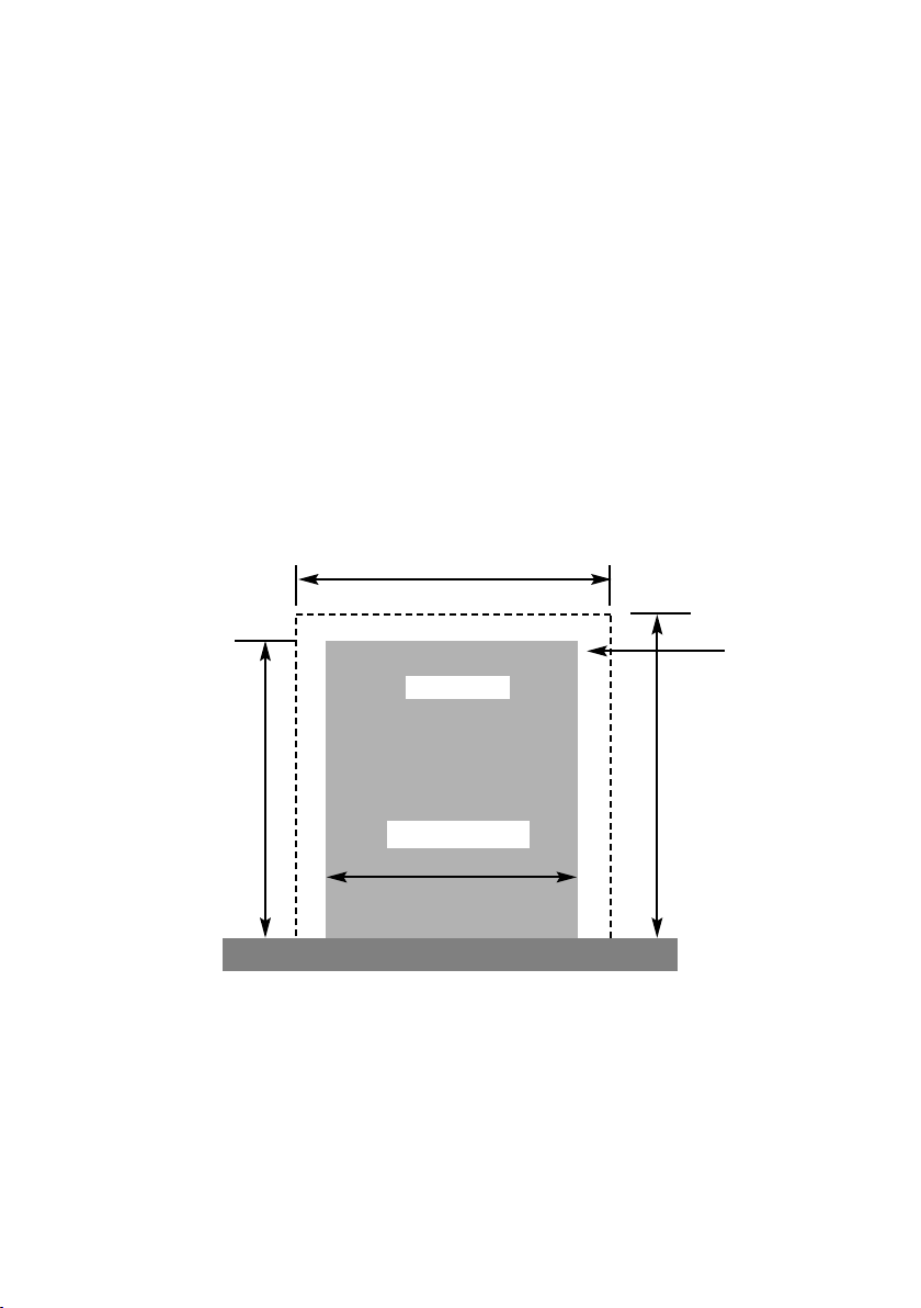
1.6 FIRE PLACE OPE I G A D CHIM EY CATCHME T SPACE
The front opening of the fire place must be a minimum of 560mm wide, and
690mm minimum in height. If the opening exceeds these dimensions then a
surround must be constructed from suitable non-combustible material to produce a
correct size opening. Any surround must be suitably sealed to the fire place to
prevent leakage. See below in fig.1
When installing into a brick built chimney, you must ensure that there is sufficient
depth to accomodate any debris which may fall from the chimney. This depth
must be sufficient to accomodate 12 litres of volumetric space.
Fire Opening
560mm Minimum
730mm
Minimum
600mm Minimum
Fig. 1
690mm Minimum
Minimum Flat
Sealing Area
6
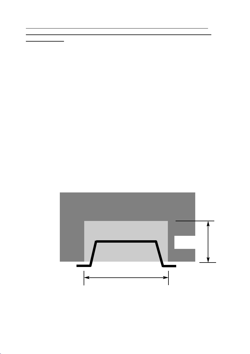
Table A - Installation De th Requirements for a Gallery Arch Tray being
installed with a Gallery Casting, requiring 12.0 litres of debris collection
volume (fig. 2).
Opening Width (mm) Minimum Depth Required (mm)
560 (minimum opening width) 200
See fig. 2 below for explanatory diagram.
Fig. 2a
The fireplace opening depth can exceed 160mm, providing that when
calculated, the void volume does not exceed 247 dm3
7
Opening Width ( e.g. 560mm)
Depth Required
(e.g. 200mm)

1.7 FITTI G TO FIREPLACES WITH EXISTI G CHAIRBRICKS A D
CO VE TIO AL BRICKBUILT CHIM EYS
This appliance is not suitable for use in fireplaces fitted with an existing chairbrick.
Any chairbrick must be removed prior to proceeding with the installation
1.8 FITTI G TO PRE-FABRICATED TWI WALL METAL FLUE BOXES
The appliance may be fitted to twin wall metal flue boxes conforming to the con-
structional requirements of BS 715 / BS EN 1856-2, (for example the Ritevent FE
175 box). The box must have a minimum flue diameter of 175mm internal and
minimum internal dimensions of 130mm deep by 690mm high by 560mm wide.
There are no maximum dimensional requirements for the box. The top face of the
box must be insulated with a minimum thickness of 50mm of non-combustible
mineral wool insulation or similar material. The flue box must stand on a non-com-
bustible base of minimum thickness 12mm.
1.9 HEARTHS
This appliance must only be installed on to a concrete or non-combustible hearth.
The hearth material must be a minimum thickness of 12mm with the top surface at
least 50mm above the floor. The hearth must be fitted symmetrically about the fire
opening and have a minimum width of 760mm and a minimum projection of
300mm forwards from the fire opening.
1.10 SPILLAGE MO ITORI G SYSTEM
This appliance is fitted with an atmosphere sensing spillage monitoring system in
the form of an oxygen sensing burner. This is designed to shut the fire off in the
event of a partial or complete blockage of the flue causing a build up of
combustion products in the room in which the fire is operated. The following are
important warnings relating to this spillage monitoring system :-
1) The spillage monitoring system must not be adjusted by the installer.
2) The spillage monitoring system must not be put out of operation.
3) When the spillage monitoring system is exchanged only a complete original
manufacturers part may be fitted.
8

SECTIO 2
I STALLATIO OF FIRE
2.1 U PACKI G THE FIRE
Carefully lift the fire out of the carton. Remove the loose item packaging carefully
from the front of the appliance. Check the contents as listed :-
Packing Check ist - Coal Fuelbed Models
1off Fire tray / burner assembly
1off Boxed ceramic base and 14 large / 4 small synthetic coals
1off oose items bag.
1off Installation / User book (Combined)
2.2 I STALLI G THE TRAY
Establish which type of flue you are intending to install the fire in to :-
225 x 225mm (9 inch x 9 inch) brick built chimneys
175mm (7 inch) diameter lined brick or stone flue, or insulated pre-fabricated
metal flue box to BS 715 / BS E 1856-2.
A spillage test must always be carried out to check satisfactory
clearance of flue products, regardless of the type of flue the
appliance is being fitted to.
To Install the Fire Proceed as follows :-
a) Carefully place the burner tray in the opening in the arch cast iron
fascia.
b) Centralise the fire in the opening and mark the centres of the two fixing
holes, which are located in the front flange, below the control knob /
piezo button on the burner tray.
OTE : If fitting the appliance to a marble or granite hearth, it may be
necessary to use the fixing location holes on the rear support of
the tray
c) Whilst the fire is in position, decide which side the gas supply is to enter
the fire from and plan accordingly. The inlet elbow can be loosened and
rotated if necessary. See Fig. 5 & 6 on page 11 for suggested pipe
routes.
9
10
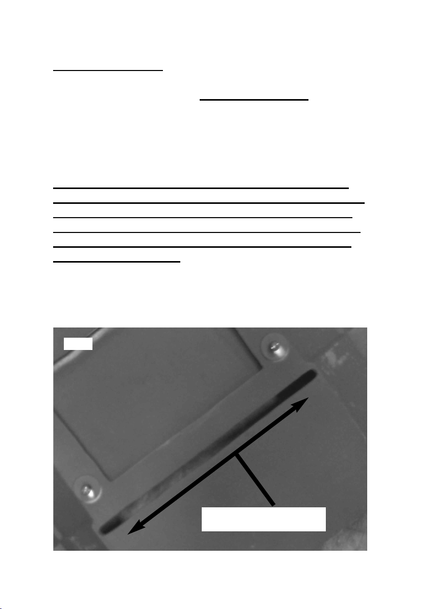
IMPORTA T OTE : IF THE CASTI G THAT YOU ARE
FITTI G THIS TRAY BUR ER I TO HAS A SLOT I THE
REAR FACE, THIS SLOT MUST BE SEALED WITH
SUITABLE SEALI G TAPE. FAILURE TO SEAL THIS
SLOT CA LEAD I SOME FLUE CIRCUMSTA CES TO
FLAME REVERSAL WHICH WILL DAMAGE THE
CO TROLS.
GALLERY FIRES WILL OT ACCEPT GUARA TEE
CLAIMS O THE BUR ER U IT THAT ARE A DIRECT
RESULT OF THESE SLOTS I THE CASTI GS OT
BEI G SEALED CORRECTLY. PLEASE SEE BELOW
(FIG. 4B) FOR A EXAMPLE OF THIS SLOT I THE
CAST IRO FASCIA’S
Slot in Rear face as indicated must be
sealed with suitable tape.
Fig. 2b

d) Carefully withdraw the fire base from the opening to enable the gas
supply and fire fixing to be completed.
e) Drill 2 off fixing holes as marked out in section b) to accomodate 2 off
no. 10 or 12 rawl plugs
f) Fit the rawl plugs (supplied)
Fig. 3 Gas Supply entering from RHS
Fig. 4 Gas Supply entering from LHS
Cast Iron Back
Approx.
40mm Fireplace
Gas Supply
Cast Iron Back
Approx.
40mm Fireplace
Gas Supply
11
OTE : For servicing reasons, the fire must not be fixed
in place using silicone or similar adhesives. Failure to
use the fixings (screws and rawlplugs) provided may
invalidate any warranty.

g) Making the gas connection
The gas connection should be made to the appliance inlet elbow using
rigid 8mm piping.
h) ift the firebase in to position and secure the base of the fire opening
with the two screws provided, ensure when fitted that the fire tray sits
level.
i) Before making the final gas connection, thoroughly purge the gas
supply pipework to remove all foreign matter, otherwise serious damage
may be caused to the gas control valve on the fire.
OTE :- Failure to correctly purge the pipework will invalidate the
guarantee
2.3 GAS TIGHT ESS A D I LET PRESSURE
a) Remove the pressure test point screw from the inlet elbow and fit a
manometer.
b) Turn on the main gas supply and carry out a gas tightness test.
c) Depress the control knob and turn anti-clockwise to the position marked
ignition / low. Hold in the control knob for a few seconds to purge the
pipe work then press the igniter button. The burner should light,
continue to hold the control knob for a few seconds then turn to the full-
on position.
ote : The burner system on this product has an integral pilot assembly. The
pilot system is part of the burner and is not a seperate component.
d) Check that the gas pressure is 20.0 mbar (+/- 1.0mbar) 8.0 in w.g.(+/-
0.4 in w.g.) for atural Gas Models.
e) After removing the manometer, ensure that the pressure test point
screw is checked for gas tightness with suitable leak detection
spray or fluid.
12

SECTIO 3
ASSEMBLI G FUEL-BED A D COMMISSIO I G
3.1 ASSEMBLI G THE FUEL-BED - Coal Fuelbed Model
a) a) Place the fuelbed base centrally on to the fuelbed support and push
fully backwards to the rear face of the cast iron back panel, ensuring
the locating groove in the fuel-bed fits onto the raised channel in the
fuel-bed support as shown in Fig 6.
Make sure that the fuelbed base is located centrally on the burner
tray. See Fig. 5 below.
Fig. 5
b) ocating groove in fuel-bed base fits onto raised channel in metal
fuel-bed support.
Fig. 6
13
Metal Fuel-bed
Support
ocating groove in
fuel-bed base

COAL LAYOUT IMAGES SHOW WITHOUT CAST BARS I POSITIO TO
ALLOW CLARITY OF IMAGES
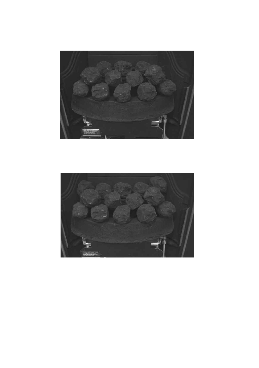
c) Fit five of the coals along the front row of the fuelbed matrix, as shown
in Fig. 7 below.
Fig. 7
d) Fit three off coals into the recess’s on the rear edge of the fuelbed, as
shown in fig. 8 below.
Fig. 8
14
e) Fit four of the coals into the space between the front and rear row of
coals as shown below in Fig. 9
Fig. 9
f) Fit the two remaining coals at each end of the second row of coals, as
shown below in Fig. 10
Fig. 10
g) The remaining four small coals can be placed randomly on the
fuelbed to give the most pleasing aesthetic.
The exact position and fit of the coals may be finely adjusted to give the best
appearance.
Warning : Use only the coal set supplied with the fire. When replacing the
coals remove the old coals and discard them. Fit a complete set of coals of
the correct type. Do not fit additional coals or any coals other than a
genuine replacement set.
15

To ensure that the release of fibres from these R.C.F (Refractory Ceramic
Fibre) articles is kept to a minimum, during installation and servicing we
recommend that you use a HEPA filtered vacuum to remove any dust
accumulated in and around the appliance before and after working on the
appliance. When replacing these articles we recommend that the replaced
items are not broken up, but are sealed within heavy duty polythene bags,
clearly labelled as “RCF waste”. RCF waste is classed as a “stable”, non
reactive hazardous waste and may be disposed of at a landfill licensed to
accept such waste Protective clothing is not required when handling these
articles, but we recommend you follow the normal hygiene rules of not
smoking, eating or drinking in the work area, and always wash your hands
before eating or drinking.
3.2 LIGHTI G THE APPLIA CE
a) Turn on the gas isolation tap.
b) Depress the control knob and turn anti-clockwise to the position
marked ignition / low rate. Hold in the control knob for a few seconds to
purge the pipe work.
c) Continue to hold-in the control knob and press the igniter button. If the
burner does not light, continue to press the igniter button until ignition
occurs. Continue to hold the control knob for a minimum of 10-15
seconds to allow the thermocouple to heat up, if the burner goes out
when the control knob is released, repeat the lighting sequence.
ote : The burner system on this product has an integral pilot assembly. The
pilot system is part of the burner and is not a seperate component.
d) Turn the control knob in the anti-clockwise direction to the high position
and the gas rate will increase to high rate (6.9 kW)
e) Turn the control knob clockwise to the low position and the gas input
will be reduced to the minimum setting (2.5 kW)
f) Slightly depress the control knob and turn to the off position, the burner
will now be extinguished.
WAR I G : If the fire goes out for any reason or is turned off and it
is necessary to re-light the fire it is important to allow the
fire to cool for 3 minutes before attempting to re-light it.
16

3.3 CHECKI G FOR CLEARA CE OF COMBUSTIO PRODUCTS
a) Close all doors and windows in the room.
b) ight the fire and allow to run for approximately 5 minutes on high
position.
c) After approximately 5 minutes hold a smoke match just inside and
below the centre of the lower front edge of the top of the fire. (It is
recommended that a suitable smoke match holder is used when check
ing for clearance of combustion products). All smoke generated should
be drawn back into the flue. If slight spillage occurs or if in doubt,
repeat the test after a further 5-10 minutes. If the test indicates that
spillage is occurring and the flue restrictor baffle has been fitted, it
should be moved to the lowest position and the test repeated after
the fire has cooled. If spillage still occurs the restrictor plate
should be removed and the test repeated.
d) If spillage persists, the flue is not functioning correctly and a fault exists.
If, after investigation the fault cannot be traced and rectified, the fire
must be disconnected from the gas supply and expert advice obtained.
e) If there is an extractor fan fitted any where in the vicinity of the
appliance, or in adjacent rooms the spillage test should be repeated
with the fan running on maximum and all interconnecting doors open.
f) After ensuring that the fire is safe to use it should be left on high
position to fully warm up. During this time a slight odour may be
noticed, this is due to the “newness” of the fire and will soon disappear.
At this stage any minor adjustments to the coals should be made
using suitable long handled tongs and taking care not to damage the
coals.
Finally, hand the Installation and Maintenance Instructions and the
Users Instructions over to the customer and explain the operation of the
fire.
17

SECTIO 4
MAI TE A CE
Servicing otes
Servicing should be carried out annually by a competent person such as a
registered engineer. This is a condition of the Gallery guarantee schemes.
The service should include visually checking the chimney and fire opening for
accumulations of debris and a smoke test to check for a positive up-draught in the
chimney.
The condition of the coals should be checked and if necessary the whole set
should be replaced with a genuine replacement set.
The burner assembly is designed to be removed as a complete unit for ease of
access. After any servicing work a gas tightness check must always be
carried out.
For Diagrams refer to Section 2
4.1 Removing the burner assembly from the fire.
4.1.1 Prepare work area (lay down dust sheets etc.)
4.1.2 Remove the fret / ash pan cover out of the way and put them in a safe
location. Remove the loose coals from the fuel bed. Remove the
fuelbed matrix
4.1.3 Isolate the gas supply and remove the inlet pipe from the appliance
inlet elbow. Unscrew and remove the two screws which retain the
burner at the base. Remove the burner assembly from the fire.
4.1.4 To refit the burner assembly. Push the burner to locate against the rear
panel of the cast and secure the burner at the base of the control panel
with two screws. Refit the gas supply pipe and carry out a gas
tightness test. The ash pan cover or can now be re-positioned.
4.2 Removing the Piezo Igniter
4.2.1 Remove the burner assembly as in section 4.1
4.2.2 Disconnect the ignition lead from the piezo and unscrew the
retaining nut on the rear of the control panel. Withdraw the piezo from
the front of the control panel. Re-assemble in reverse order and carry
out a gas tightness test. Ensure the heatshield is re-fitted.
18

4.3 Removing the Control Tap from the fire.
4.3.1 Remove the burner assembly as in section 4.1.
4.3.2 Pull the control knob off the control tap spindle.
4.3.3 oosen and remove the two gas pipe retaining nuts from the control
tap and release the ends of the gas pipes from the control tap body.
Remove the push in thermocouple from the end of the control tap.
4.3.4 Unscrew the control tap locknut from the front of the control panel and
remove the control tap.
4.3.5 To refit a control tap, reassemble in reverse order noting that the control
tap locates with a flat in the control panel. Carry out a gas tightness
test after re-assembly.
4.4 Removing the Thermocouple
4.4.1 Remove the burner assembly as in section 4.1
4.4.2 Remove the push in thermocouple from the end of the control tap and
and remove the thermocouple retaining nut from the mounting bracket
on the burner assembly.
4.4.3 Re-assemble in reverse order and carry out a gas tightness test.
PARTS SHORTLIST
Replacement of any other parts must be carried out by a competent person such
as a registered gas installer. The part numbers of the main replaceable parts are
as follows, these are available from Gallery (see rear page for contact details)
Coal Pack B-108860 Coal Fuelbed Matrix B-108850
Coal / Ceramic Set (Complete) B-108840
NG Gas Valve B-67090
PG Gas Valve B-76320
NG Burner Engine B-72580
PG Burner Engine B-76960
Ignition Wire B-67910
19

SECTIO FIVE - USER I STRUCTIO S
5.1 About your Arch Tray
The Arch Tray incorporates a unique and highly developed fuel bed which gives
the realism of a loose coal layout combined with realistic flames and glow. The
use of durable ceramic material in the construction of the fuel-bed components
ensures long and trouble free operation.
When first using the new fire a slight smell may be noticed. This is due to starch
used in the manufacture of the soft ceramic coals , it is non-toxic and will soon
disappear.
Please take the time to fully read these instructions as you will then be able to
obtain the most effective and safe operation of your fire.
IMPORTA T SAFETY I FORMATIO
WAR I G
This appliance has a naked flame and as with all heating appliances a
fireguard should be used for the protection of children, the elderly and
infirm. Fireguards should conform to B.S. 8423 : 2002 (Fireguards for use
with gas heating appliances).
It is important that this appliance is serviced at least once a year by a registered
gas installer and that during the service the fire is removed from the fire opening
and the chimney or flue visually checked for fallen debris or blockages which must
be removed. The chimney should also be checked to ensure
clearance of flue products. These are conditions of the manufacturers
guarantee. After installation or during servicing a spillage test must always
be carried out.
Rubbish of any type must NEVER be thrown onto the fuel-bed, this could affect
safe operation and damage the fire.
Any debris or deposits should be removed from the fuel-bed from time to time.
This may be carried out by referring to the cleaning section as described later in
this book.
Only the correct number and type of coals must be used and only
complete and genuine replacement sets must be sourced from Gallery (See rear
cover of this book for contact details)
The appliance must only be used with the coal set supplied and must not be used
with other coals.
Always keep furniture and combustible materials well clear of the fire and never
dry clothing or items either on or near to the fire. Never use aerosols or
flammable cleaning products near to the fire when it is in use.
20
Table of contents
Other BFM Indoor Fireplace manuals

Popular Indoor Fireplace manuals by other brands

Nordpeis
Nordpeis N-24 round Installation & user manual

Pur Line
Pur Line CHE-610 user manual

Heat & Glo
Heat & Glo SOULSTICE-LP owner's manual

Quality Craft
Quality Craft M650-38A-OAK instruction manual

Heat & Glo
Heat & Glo 6100PLUS owner's manual

foc.us
foc.us Filiofocus 1600 Design installation & operating manual


Comfortflame
Comfortflame Westerly32ZMN Installation and operation instructions

RealFlame
RealFlame Lannon 3300 Assembly instructions

RealFlame
RealFlame 11802 LP owner's manual

Heat & Glo
Heat & Glo Everest owner's manual

Heat & Glo
Heat & Glo ATS-AU-D Installation and operation instructions

Vanguard
Vanguard Vi33NRB OWNER'S OPERATION AND INSTALLATION MANUAL