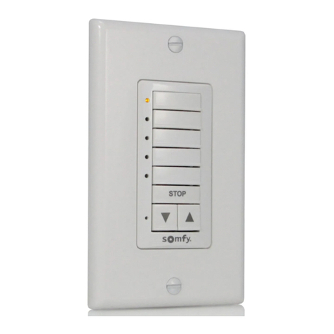
BG Electrical TWE7 Instruction manual

Technical Data
Wall Timer Switches
Brief product description:
The subtle design will blend with any décor - suitable
for domestic or commercial installations.
Timer allows lighting to be turned on and off when
you are away.
Features:
Hinged cover conceals the controls.•
8 separate on and off programme•
settings
Battery backup for the timer settings in•
the event of a power failure (24 hours)
Can be used as a standard light switch•
3A Fuse to BS646 fitted•
Easily changed from BST to GMT. Not•
suitable for fluorescent lighting,
Not suitable for use with dimmer•
switches when used in a 2 way
lighting circuit.low energy CFL or low
voltage lighting
Standard(s)
Rating
Terminal Capacity
RoHS Directive
WEEE Directive
Mounting Box Depth(Min)
Fixing Centres
Size
BSEN60669-1
40 - 400W Tungsten filament lamps
2 x 1.5mm²
No
No
16mm
60.3mm
86mm x 86mm x 46mm
Technical Specifications
Cat No. Description
Product Each IndividualInner Box Inner
Box
Inner BoxOuter Box Outer
Box
Outer Box
Packaging Type Pack Quantity Barcode
TWE7 7 Day Wall Timer Nexus
Clamshell
1 5050765018791Nexus Inner 5Nexus Outer 50
Packaging Information
Line Diagrams
TWE7
TWE7 7 Day Wall Timer
Cat No. Description Dimension (W x L x H) cm Weight (g) CMB (m3)
xxxx xxxxxxxx xxxxxxxxx xxxxx xxx
Product EachInner Box Inner
Box
Outer Box Outer
Box
Outer Box
Weights & Dimensions
TWE7

Wall Timer Switches
Installation Information
Safety Warning
Before use please read carefully and use in accordance with these safety wiring instructions.
Before commencing any electrical work ensure the supply is switched off at the mains. Either by switching off the consumer unit or by removing the appropriate fuse.
Wiring should be in accordance with the latest edition of the IEE regulations (BS 7671).
Wire Identification – Twin & Earth Cable
EARTH = Green/Yellow Sleeving
NEUTRAL = Black (pre Apr 04) / Blue (after Apr 04)
LIVE = Red (pre Apr 04) / Brown (after Apr 04)
To prevent fire hazard always use cable of the correct rating, size and type for the application.
Note - If your installation uses a four lug metal mounting box, remove the top and bottom lugs or bend fully back.
Technical Helpline: 0845 194 7584
If in doubt consult a competent electrician.
1. Manual Switch
2. Mode Selector
3. "CLOCK" Button
4. "PROG" Button
5. "Time Recall/Cancel" Button
6. "MIN" Button
7. "HOUR" Button
8. "DAY" Button
9. "Reset" Button
10. Fuse (3 Amp, BS646)
11. Red Indicator Light
12. Display
13. Control Cover
Installation Instructions
The unit is designed to be used in place of a standard light switch in a one-way or two-way
standard circuit. Connections to other circuits are possible but beyond scope of this instruction,
so please consult a qualied electrician for advice. The rear face of the unit has a terminal block
with 3 connections:
If the Timer switch is required at the end of circuit without an existing Live connection, one of
the existing wires will need to be used to extent the Live connection to the unit.
Remove existing light switch & note the numbers of wires, excluding any Earth connections
& proceed as below:
For a one-way circuit there should be only 2 wires.
Typical One-Way Circuit
Connect:
1. Live wire to the LIVE terminal.
2. Switched Live wire to the LOAD terminal
For a two-way circuit, depending on how it is wired, there may be either 3 wires at both
switches OR 3 wires at one switch & 5 wires at the other.
Typical Two-Way Circuit (3 Wires Both Ends)
Connect:
1. Live wire to the LIVE terminal.
2. COM (or C) from other switch to LOAD terminal
3. L1 from other switch to 2-WAY terminal
4. Switched Live wire to the other switch COM terminal L2 on other switch has no connection,
& wire MUST be isolated by connecting to a seperate terminal block or similar.
This circuit normally uses 3-core insulated cable to connect between the COM, L1 & L2 ter-
minals between both switches. The end of the circuit with 5 wires also includes the Switched
LIVE & LIVE wires.
Typical Two-Way Circuit (5 Wires One End, 3 Wires Other)
Connect:
1. Live wire to the LIVE terminal.
2. COM (or C) from other switch to LOAD terminal
3. L1 from other switch to 2-WAY terminal
4. Switched Live wire to LOAD terminal
L2 on other switch has no connection, & wire MUST be isolated by connecting to a separate
terminal block or similar.
NOTES
- The internal battery may require up to 2 hours to charge before first use, or long periods of non-use. To charge the unit must be connected to the mains power supply – and the switch turned
ON (under load conditions)
- Timer tolerance +/- 2min per month
- Max load = 400W or 2.5 Amps
- Only suitable for most tungsten lament lamps
IMPORTANT
Do not use with fluorescent lighting, low energy CFL, low voltage
LIVE: for connecting Live
LOAD: for connecting switched live to Light bulb or Load
2-WAY: for use with 2-way circuits only
Note - It is important that a Live connection to the unit exists to provide permanent power for
the timer, especially on 2-way circuits where the Live connection will only be at one switch.

Wall Timer Switches
Setup Instruction
3. Press PROG to conrm selection, and the display then display “1 OFF”, you can now enter the OFF time using the HOUR and MIN buttons.
4. Press PROG to conrm selection, the display will show “2 ON” for a 2 program.
5. Repeat procedure to set up to 8 dierent programs.
6. Pressing CLOCK at anytime means you will leave the programming mode. No activity for 30 seconds in programming mode will mean timer will return to normal time display mode.
Cancelling Programs
Pressing R during the program time setting will cancel the current time setting & disable that program. The display will show “--:--“.
Pressing R again recalls previous set time.
Reviewing Programs
To review the programs press PROG, and press again as required to review each setting, adjustments can be made accordingly
Reset
To clear time and program settings press RESET. The indicator light & any connected light will remain on for 30 secs to indicate reset has been pressed.
Auto / Manual Switch
The timer can operate in either Manual or Timer (Auto) mode – via the mode switch (2).
The unit is in Timer (Auto) mode when the switch is to the left & in manual mode when to the right. When in Auto mode, the red indicator light (11) will illuminate & display will show “AUTO” near
bottom.
When in Timer (Auto) mode the time function can be overridden by pressing the main rocker switch (1). The program will then proceed to the next setting.
For example,
Light is ON, and in Timer mode – pressing switch (1) will turn o light. Timer will stay in Auto mode, and will remain in this state until the next program time command is reached. In manual mode
the product will operate as a standard light switch.
Replacing The Fuse
The Fuse will need to be replaced if there is incorrect operation of timer unit. This may be as a result of incorrect wiring or possibly after replacing a lightbulb.
1. Using a at bladed screw-driver, carefully leaver open the fuse carrier.
2. Pull the carrier out and replace the fuse.
Note - the fuse carrier cannot be fully removed from the product.
3. Fit a new 3 Amp fuse (to BS646 – Not standard plug type fuse) and push the carrier home so it sits ush with the surface of the faceplate.
Replacing A Failed Light Bulb
In the event of a light bulb failure, always disconnect the power before replacing the bulb. This should be achieved by switching o at the consumer unit, or removing the fuse from the timer (as
described above).
Note: A failed light bulb will prevent the timer unit from operating correctly.
Setting The Current Time
To access the controls, open cover from the top and pull towards you.
1. Press RESET button using a ball point pen.
2. To set Hour – Press & hold CLOCK and then press HOUR to advance Hour.
3. To set Minute – Press & hold CLOCK and the press MIN to advance Min.
4. To set Day – Press & hold CLOCK and then press DAY to advance Day
Note – holding down the HOUR, MIN or DAY buttons will advance the setting rapidly for quicker set-up.
British Summer Time Adjustment
The timer has the ability to adjust for British Summer Time (BST).
Press HOUR and MIN together, the display will show “S” on the right side of the display, and the time will advance 1 hour. Repeat process to switch back to normal time setting – “S” will disappear
Programming The Timer
The indicator light (11) on the timer will ash repeatedly when it contains no program settings.
A maximum of 8 dierent programs can be set (8 On & 8 O) per day.
One program setting can be made for either, a single individual day, weekday, weekend, workdays (inc Sat), or groups of days (4 options).
To set a program,
1. Press PROG button to enter the programming mode, display will show “1ON” in the bottom left corner.
2. Press the HOUR, MIN and DAY to enter the required information.
Note – when pressing DAY the display will cycle through the following options in order;
- All Days : Display will show all days visible on Screen
- Individual Days: MO – TU – WE – TH – FR – SA– SU
- Week Days: MO, TU, WE, TH, FR
- Weekend: SA, SU
- Workdays: MO, TU, WE, TH, FR, SA
- Group 1: MO, WE, FR
- Group 2: TU, TH, SA
- Group 3: MO, TU, WE
- Group 4: TH, FR, SA
