BGS technic BGS 3200 User manual

BGS technic KG
Bandwirkerstr. 3
42929 Wermelskirchen
Tel.: 02196 720480
Fax.: 02196 7204820
mail@bgs-technic.de
www.bgstechnic.com
© BGS technic KG, Vervielfältigung und Weiterverwendung verboten
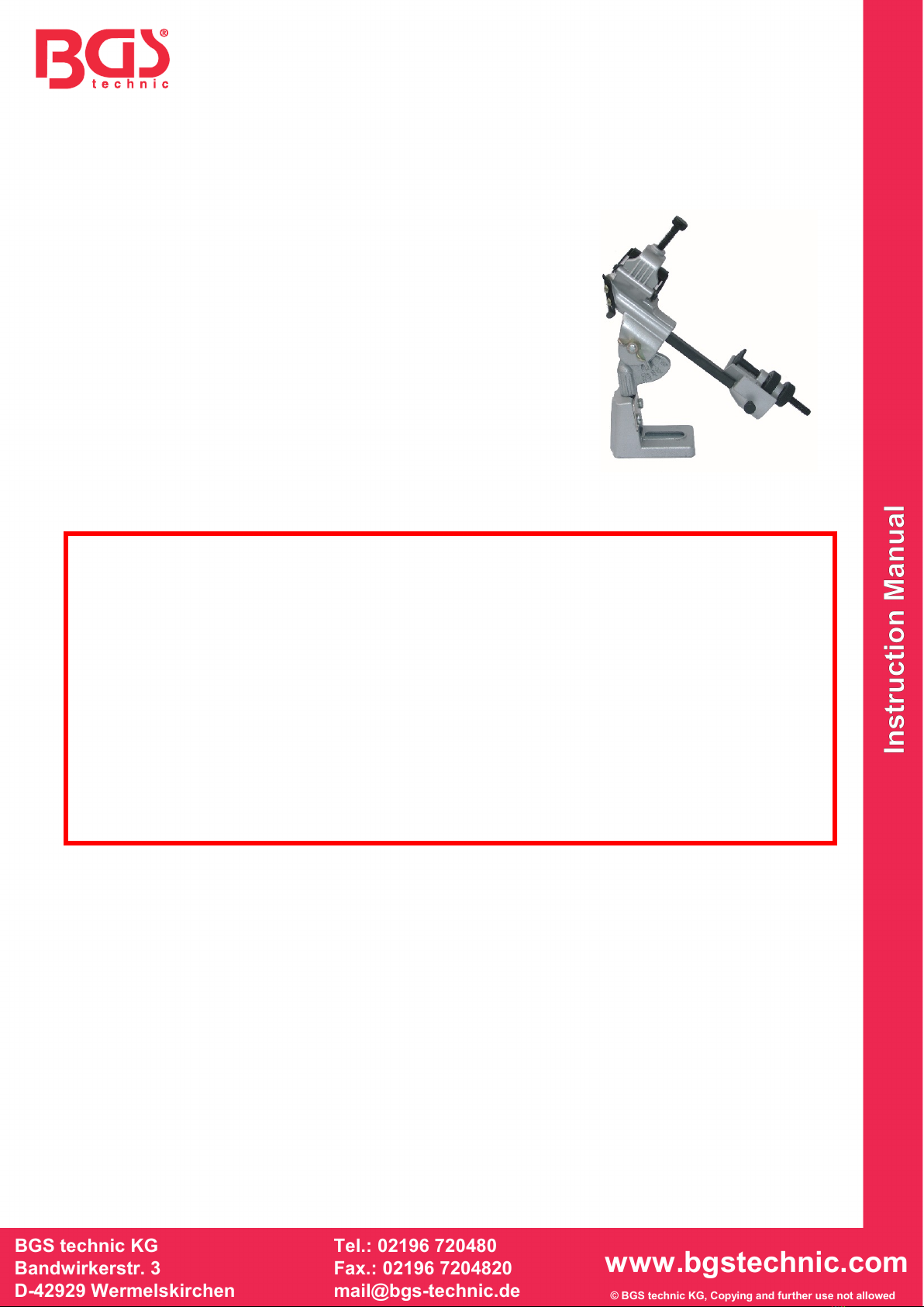
Art. 3200
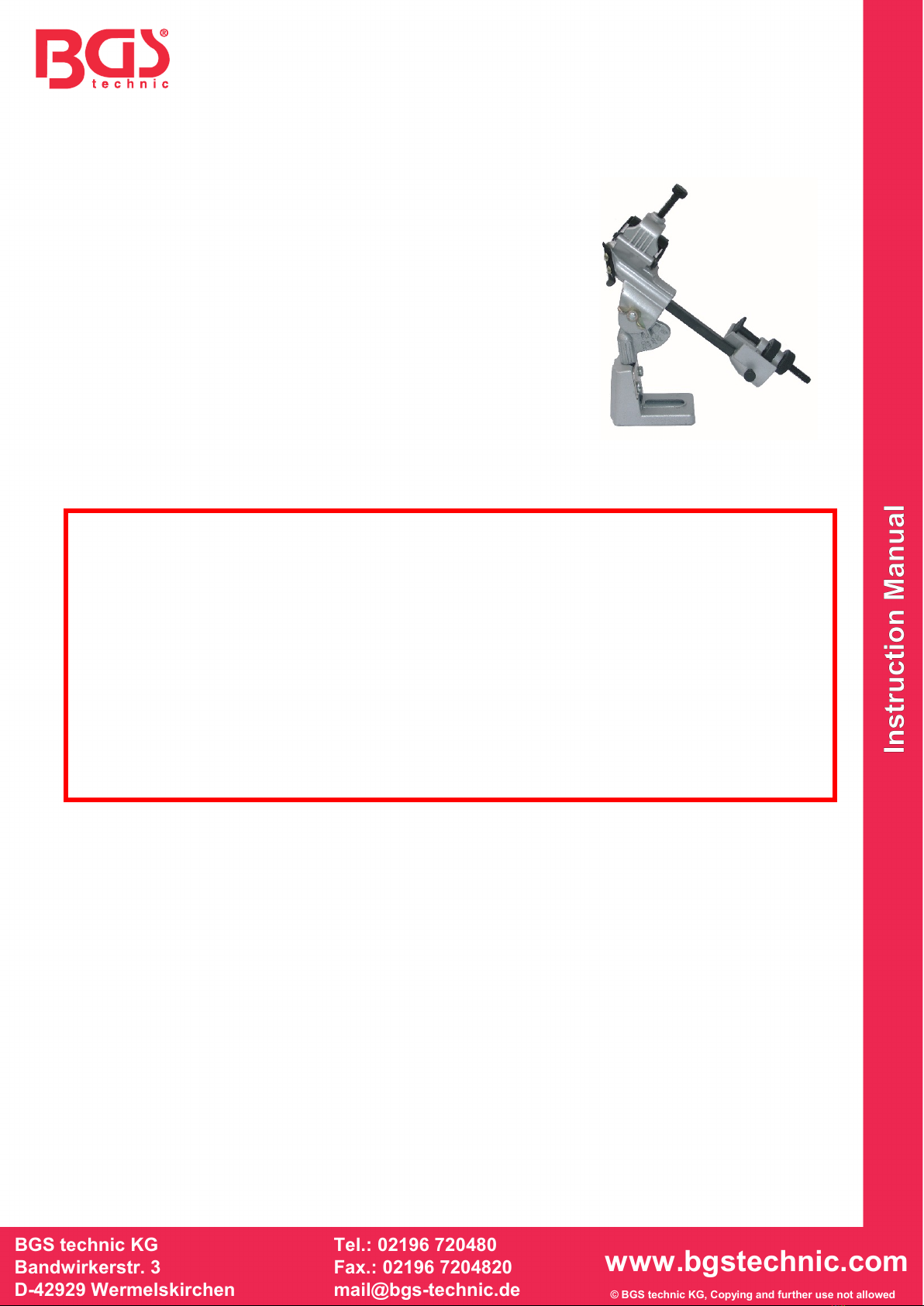
Anschleifvorrichtung, für Spiralbohrer
Sehr geehrter Kunde,
bitte machen Sie sich in der Reihenfolge der Kapitel mit dem Gerät
vertraut, bewahren Sie diese Bedienungsanleitung für spätere
Zwecke gut auf. Diese Bedienungsanleitung enthält wichtige
Hinweise zur Inbetriebnahme und Handhabung. Legen Sie die
Anleitung dem Produkt bei, wenn Sie es an Dritte weitergeben!
Bitte lesen Sie auch alle Sicherheitshinweise! Diese sollen Ihnen
den sachgemäßen Umgang erleichtern und Ihnen helfen,
Missverständnisse und Schäden vorzubeugen.
SICHERHEITSHINWEISE
Beachten Sie bitte zur Vermeidung von Fehlfunktionen, Schäden und gesundheitlichen
Beeinträchtigungen folgende Hinweise:
•Personen mit eingeschränkten physischen, sensorischen oder geistigen Fähigkeiten dürfen das
Gerät nicht benutzen, es sei denn sie werden durch eine für ihre Sicherheit zuständige Person
beaufsichtigt oder erhalten von der zuständigen Person Anweisungen, wie das Gerät zu
benutzen ist.
•Tragen Sie geeignete Arbeitskleidung, binden Sie lange Haare zusammen und tragen Sie
keinen Schmuck, um zu verhindern, dass sie von beweglichen Teilen erfasst werden.
•Benutzen Sie immer eine Schutzbrille beim Schleifen.
•Halten Sie den Bohrer stets fest und benutzen Sie zum Schutz gegen Verletzungen
Arbeitshandschuhe.
•Prüfen Sie den Zustand und die Befestigung der Schutzvorrichtungen und entfernen Sie keine
mechanischen oder elektrischen Schutzvorrichtungen.
•Arbeiten Sie nicht mit einem beschädigten Schleifstein, Es besteht Verletzungsgefahr. Tauschen
Sie einen defekten Schleifstein umgehend.
•Beachten Sie bei der Benutzung der Schleifmaschine auch diese Sicherheitshinweise.
•Bearbeiten Sie keine beschädigten bzw. abgebrochenen Bohrer.
•Benutzen Sie die Anschleifvorrichtung nicht, wenn sie beschädigt ist.
VORBEREITUNG
Packen Sie die Spiralbohrer-Anschleifvorrichtung aus und überprüfen Sie alle Teile auf evtl.
Transportschäden.
Für den Anschliff selbst benötigen Sie eine normale, fest montierte Schleifmaschine (z. B.
Doppelschleifer). Benutzen Sie eine feine Schleifscheibe bzw. eine Schleifscheibe für Hartmetall.
Montieren Sie die Anschleifvorrichtung so vor den Schleifstein, dass Sie den Bohrer bequem an die
Schleifscheibe führen können.
WARTUNG, REINIGUNG UND LAGERUNG
Reinigen Sie nach jedem Gebrauch die Anschleifvorrichtung gründlich und entfernen Sie
Schleifstaub.
Setzen Sie zum Reinigen lediglich ein trockenes Tuch, keine lösungsmittelhaltigen Reinigungsmittel,
Spiritus oder Alkohol ein.
Tauchen Sie die Vorrichtung nicht ins Wasser und setzen Sie sie keinerlei Feuchtigkeit aus!
Halten Sie die Vorrichtung und insbesondere die Einstellschrauben frei von Öl und Fett.
Wechseln Sie einen beschädigten Schleifstein umgehend aus - ansonsten besteht hohe
Verletzungsgefahr.

BGS technic KG
Bandwirkerstr. 3
42929 Wermelskirchen
Tel.: 02196 720480
Fax.: 02196 7204820
mail@bgs-technic.de
www.bgstechnic.com
© BGS technic KG, Vervielfältigung und Weiterverwendung verboten
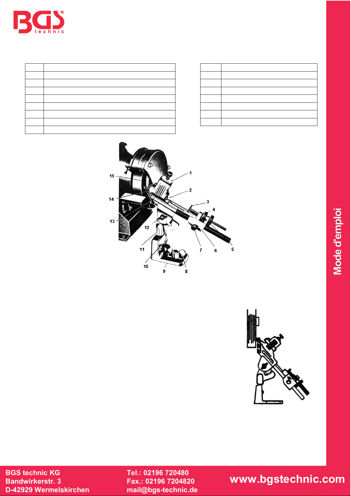
AUFBAU
Nr.
Bezeichnung
Nr.
Bezeichnung
1
Andruckvorrichtung, gefedert
9
Gerätefuß
2
Bohrerwanne
10
Horizontalschwenklager
3
Bohreranschlag
11
Schwenkachse
4
Vorschubschraube
12
Schneidwinkeleinsteller
5
Feststellschraube
13
Bohrlippenanschlag
6
Vorschubschlitten
14
Bohrwannenspitze
7
Schlittenfeststellschraube
15
Schleifscheibe
8
Flügelmutter
ZUSAMMENBAU
1. Montieren Sie die Schleifmaschine fest z. B. auf einer Werkbank.
Beachten Sie dabei, dass zur Montage der Anschleifvorrichtung seitlich
von der Schleifmaschine genügend Platz bleiben muss. Evtl. muss die
Schleifscheibenschutzvorrichtung so verstellt werden, dass der freie
Bereich der Schleifscheibe gegenüber der Anschleifvorrichtung steht.
Der Bohrer sollte von einem Bereich der Schleifscheibe angeschliffen
werden, der links von der Antriebsnabe der Maschine liegt und nach
Möglichkeit in gleicher Höhe oder etwas tiefer als die Antriebsnabe der
Maschine.
2. Positionieren Sie die Anschleifvorrichtung vor der Schleifscheibe und
parallel zur Schleifscheibe. Befestigen Sie die Anschleifvorrichtung mit
einer Flügelmutter (8) an die Werkbank (Abstand zur Schleifscheibe ca.
6 cm). Legen Sie ggf. ein Zwischenstück (Holz), um die richtige Höhe
zur Schleifscheibe zu erreichen.
3. Um genau den richtigen Abstand zur Schleifscheibe zu ermitteln, legen
Sie ggf. einen Bohrer ein und montieren Sie dann die Vorrichtung exakt
vor der Schleifscheibe.

BGS technic KG
Bandwirkerstr. 3
42929 Wermelskirchen
Tel.: 02196 720480
Fax.: 02196 7204820
mail@bgs-technic.de
www.bgstechnic.com
© BGS technic KG, Vervielfältigung und Weiterverwendung verboten
BENUTZUNG
1. Stellen Sie zunächst mit der Schneidwinkeleinsteller (12) der gewünschte Anschliffwinkel
entsprechend des geplanten Einsatzes des Bohrers ein:
59° - allgemeiner Einsatz
88° - dünne Materialien, beugt Ausreißen vor
68° - für dünne Bohrer mit schnellem Vortrieb
49° - für weiche Metalle wie Kupfer, Blei, weiche Legierungen
41° - für Senkbohrer
2. Lösen Sie den Vorschubschlitten (6) mit der Schraube (7), drehen Sie die Vorschubschraube (4)
ganz zurück und legen Sie den Bohrer ein. Dieser muss mit seiner Spitze etwa
um das Maß seines Durchmessers über die Bohrwannenspitze (14) hinausragen.
3. Ziehen Sie nun die Schlittenfeststellschraube (7) fest und die Halteschraube der
Andruckvorrichtung (1) leicht an, nur so viel, dass der Bohrer gerade festgehalten
wird. Achten Sie auch darauf, dass die Spiralnut des Bohrers am Anschlag liegt.
4. Lösen Sie die Flügelmutter (8) im Fuß der Anschleifvorrichtung und verschieben
Sie die Anschleif-vorrichtung bis ein Abstand der Bohrerspitze von ca. 0,5 mm
zur Schleifscheibe besteht. Dabei muss die Bohrwannenspitze (14) genau
senkrecht vor der Schleifscheibe stehen.
5. Lösen Sie die Feststellschraube (5) etwas, schalten Sie die Schleifmaschine ein und schieben Sie
durch Drehen der Vorschubschraube (4) den Bohrer vor, bis er den Schleifstein berührt.
Schwenken Sie die gesamte Vorrichtung (am Vorschubschlitten erfassen) nach rechts. Damit wird
automatisch der richtige Anschliff hergestellt.
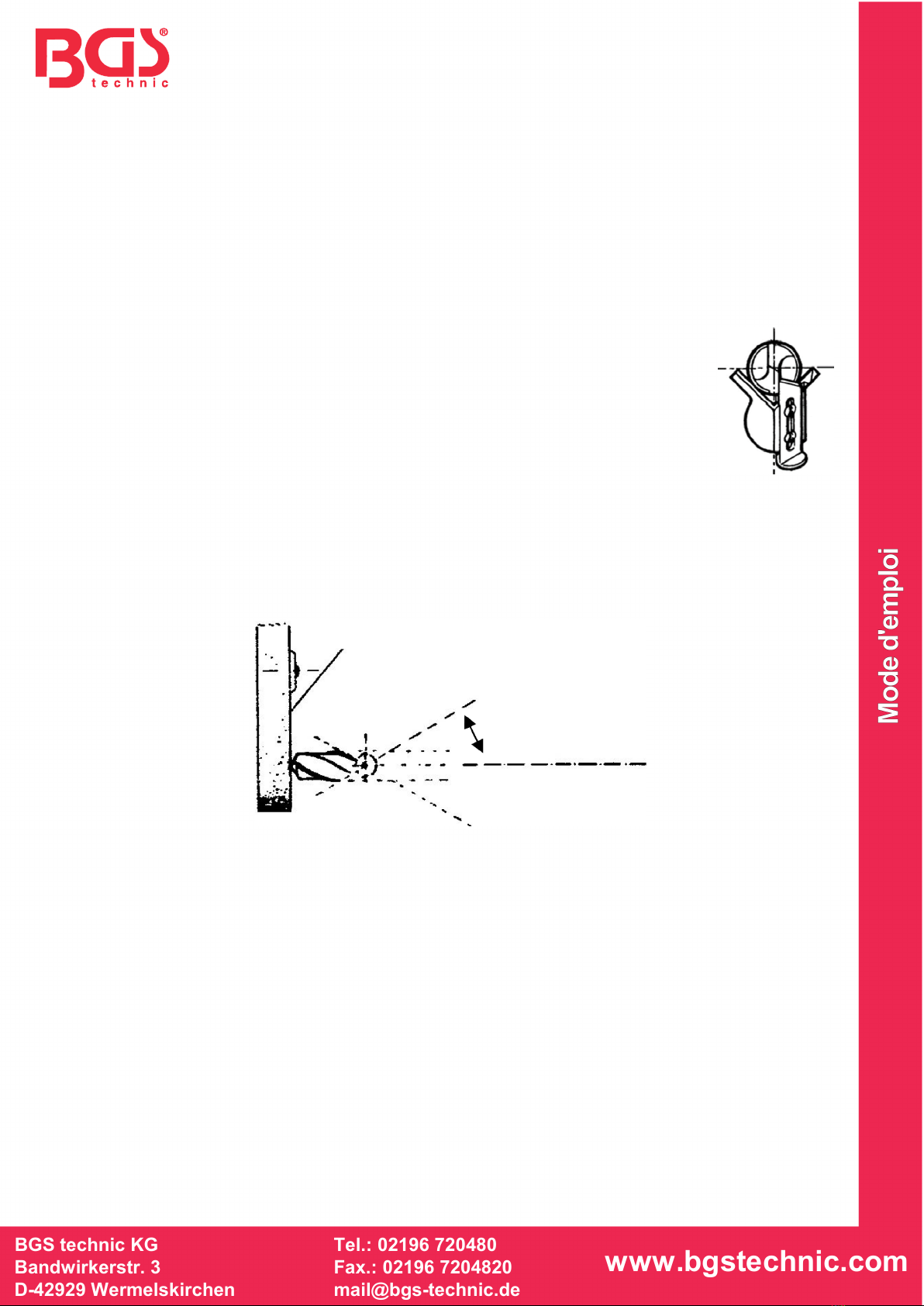
Ansicht von oben
Dadurch, dass die Schwenkachse (11) nicht genau durch die Mitte der Bohrerwanne (2) geht,
bewirkt diese „Ungenauigkeit“ den richtigen Anschliff der Schneide und der Hinterschliffe. Deshalb
dürfen Sie die Schwenkachse (11) nur nach rechts drehen.
Je nach Abnutzungsgrad des Bohrers schieben Sie den Bohrer mit der Vorschubschraube (4)
weiter vor. Arbeiten Sie langsam, damit der Bohrer nicht überhitzt wird und ausglüht. Ist längeres
Schleifen nötig, legen Sie Pausen zur Abkühlung ein. Nach dem Anschleifen der einen Flanke des
Bohrers ziehen Sie die Feststellschraube (5) fest. Damit wird die gleiche Lage für die andere
Flanke festgelegt.
6. Lösen Sie die Halteschraube der Andruckvorrichtung (1) und nehmen den Bohrer heraus. Drehen
Sie ihn, dass jetzt die andere Flanke unten am Anschlag liegt. Drehen Sie die Vorschubschraube
(4) zurück und wiederholen Sie den Anschliff für diese Flanke. Bei stark abgenutztem Bohrer,
müssen Sie den Schliff wiederholen.
Ist dennoch nicht das gewünschte Spitzenbild erreicht, wiederholen Sie den Schliff mit einem
weiter über den Anschlag herausgeschobenen Bohrer (mehr als den Bohrerdurchmesser). Weitere
Ausführungen zum richtigen Anschleifen von Bohrern finden Sie im folgenden Kapitel.
Schleifscheibe
Nicht schwenken!
Schwenken!

BGS technic KG
Bandwirkerstr. 3
42929 Wermelskirchen
Tel.: 02196 720480
Fax.: 02196 7204820
mail@bgs-technic.de
www.bgstechnic.com
© BGS technic KG, Vervielfältigung und Weiterverwendung verboten
RICHTIGES SCHLEIFEN, FEHLERURSACHEN UND FEHLERBEHEBUNG
•Das fachgerechte Schleifen eines Bohrers setzt trotz der Maschinenhilfe mit vorgegebenen
Schleifwinkeln und -bewegungen etwas Erfahrung und vor allem Sorgfalt beim Umgang mit dem
Bohrer voraus.
•Nachstehend erhalten Sie einige Hinweise zum ordnungsgemäßen Anschleifen des Bohrers und
zur Vermeidung von Fehlern. Diese Hinweise sind jedoch keine Garantie für einen
ordnungsgemäßen Schliff Ihres Bohrers. Letztendlich entscheidet eigenes Geschick, der Zustand
von Bohrer und Schleifscheibe über das Ergebnis.
BEGRIFFSERKLÄRUNG
•Berühren Sie nicht die Bohrerspitze nach dem Schleifen! Es besteht Verbrennungsgefahr!
•Vor allen Arbeiten am Gerät, schalten Sie die Schleifmaschine ab und ziehen Sie den Netzstecker
aus der Steckdose. Führen Sie keine Arbeiten an laufender Maschine aus!
•Schleifen Sie nicht zu lange. Kontrollieren Sie öfter den Schleifvorgang! Verringern Sie den Druck
auf den Bohrer beim Schleifen.
•Bohrer mit großem Durchmesser müssen länger geschliffen werden, bis sie wieder scharf sind.
Schleifen Sie in mehreren kurzen Durchgängen beide Flanken wechselseitig.
•Lassen Sie den Bohrer zwischen den Schleifdurchgängen abkühlen bzw. kühlen Sie ihn in Wasser
ab.
•Ist die Spitze blau angelaufen, so ist sie beim Schleifen überhitzt worden. Kühlen Sie die Spitze in
Wasser ab.
•Ist die Spitze nicht in der Mitte (eine Flanke ist scharf, die andere nicht), so schleifen Sie
die kürzere Flanke nochmals nach. Dieser Fehler wird durch gleichmäßigen Druck auf
den Bohrer beim Schleifen beider Flanken sowie gleiche Schleifzeiten für beide Flanken
vermieden.
•Vor allem bei Bohrern mit größerem Durchmesser und stärkerer Abnutzung kann das
Schleifen mit dem Bohrerschärfgerät u. U. nicht zu befriedigenden Ergebnissen führen. Beachten
Sie, dass das Gerät vorwiegend für das periodische Nachschleifen, aber nicht für das komplette
Aufarbeiten stark verschlissener, dickerer Bohrer konzipiert ist.
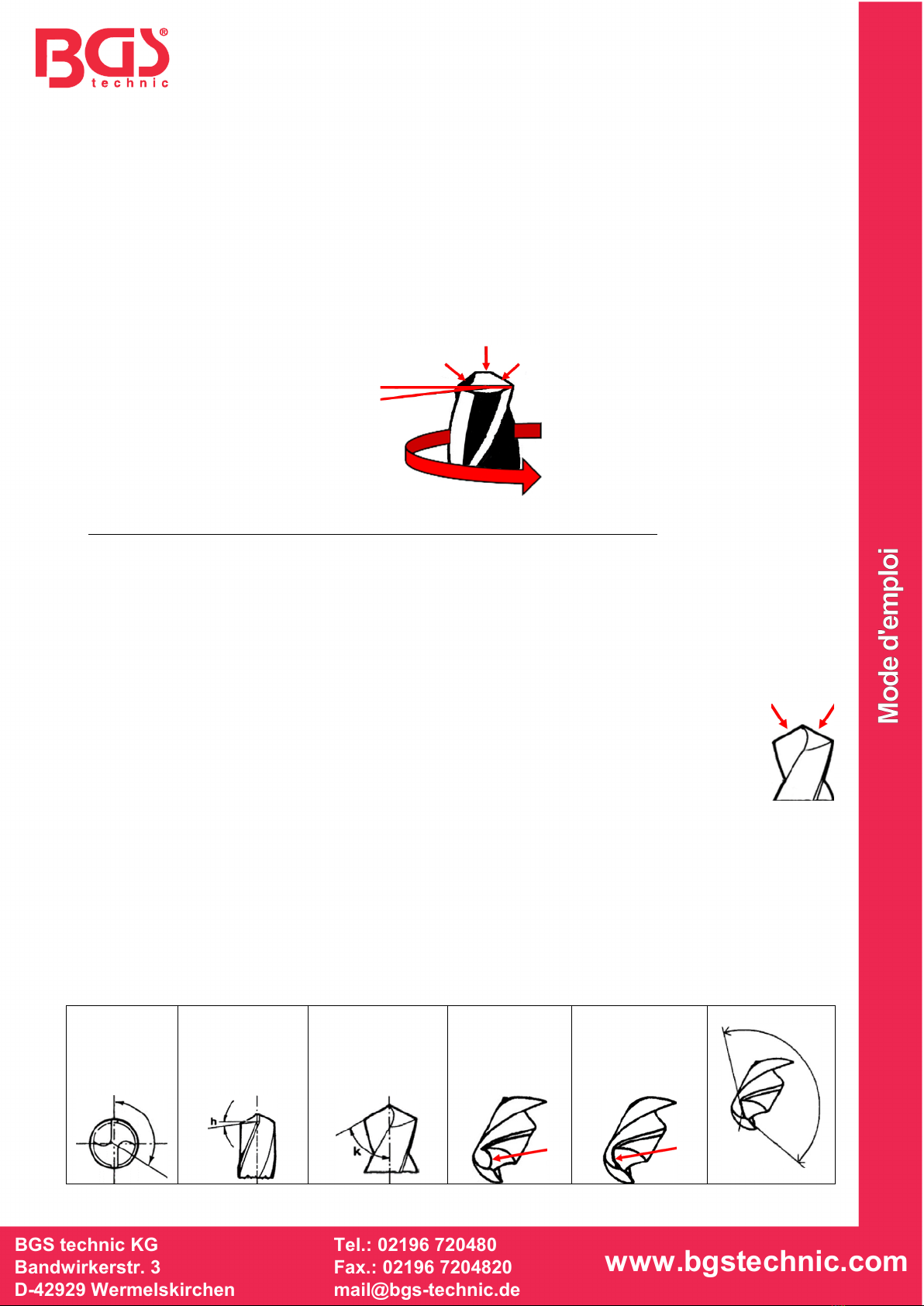
Der Spitzenwinkel wird durch den fest vorgegebenen Anschliffwinkel und den Schwenkbereich beim
Anschleifen eingestellt.
Spitzenwinkel kann je nach Material abweichen.
Aluminium: 130 - 140°
Kupfer, Messing: 120 - 130°
Stahl, Guss: 110 -120°
Kunststoffe: 50 - 90°
Spitzenwinkel
125 – 135°
Schneidwinkel
h 8 – 12°
Anschliffwinkel k
Einstellbar mit
Schneidwinkel-
einsteller (12)
Falsch
Schneide
rückgewölbt
Falsch
Schneide
vorgewölbt
Richtig
Schneide
Schneide
Spitze
Schneidwinkel
BGS technic KG
Bandwirkerstr. 3
D-42929 Wermelskirchen
Tel.: 02196 720480
Fax.: 02196 7204820
mail@bgs-technic.de
www.bgstechnic.com
© BGS technic KG, Copying and further use not allowed
BGS 3200
Drill Grinding Attachment for Twist Drills
Dear customer,
Please familiarize yourself with the proper usage of the device by
reading and following each chapter of this manual, in the order
presented. Keep these operating instructions in a safe place for
future reference. The operating instructions contain important
information on commissioning and handling. Enclose the
instructions with the product when handing over to third-parties!
Please also read all safety instructions! These should make the
correct use easier and help you to prevent misunderstandings and
damage.
SAFETY NOTES
To avoid malfunctions, damage and health impairments, please observe the following notes:
•Persons with restricted physical, sensory, or mental capabilities may not use the device unless
they are supervised by a person who is responsible for their safety or have received instructions
from the responsible person in how the device should be used.
•Wear suitable work clothes, tie long hair together and do not wear any jewellery in order to
prevent them from getting caught by moving parts.
•Always wear safety glasses when grinding.
•Always hold the drill bit tight and wear work gloves to protect against injury.
•Check the state and fixing of the protective equipment and never remove any mechanical or
electrical protective equipment.
•Do not work with a damaged grinding stone. There is a risk of injury. Replace a damaged
grinding stone immediately.
•Also observe these safety instructions when using the grinding machine.
•Do not grind damaged or broken drill bits.
•Do not use the drill grinding attachment if it is damaged.
PREPARATION
Unpack the twist drill grinding attachment and check the parts for potential transport damage.
For the grinding itself, you need a normal firmly mounted grinding machine (e.g. double grinder). Use
a fine grinding disc or a grinding disc for carbide. Mount the drill grinding attachment in front of the
grinding stone such that the drill bit can be conveniently guided to the grinding disc.
MAINTENANCE, CLEANING AND STORAGE
Thoroughly clean the drill grinding attachment after each use, and remove the grinding dust.
For cleaning, use only a dry cloth. Do not use any cleaning agent containing solvents, industrial
alcohol or alcohol.
Do not immerse the attachment in water and never expose it to any moisture!
Keep the attachment and, in particular the adjustment screw free from oil and grease.
Change a damaged grinding stone immediately otherwise there is a high risk of injury.

BGS technic KG
Bandwirkerstr. 3
D-42929 Wermelskirchen
Tel.: 02196 720480
Fax.: 02196 7204820
mail@bgs-technic.de
www.bgstechnic.com
© BGS technic KG, Copying and further use not allowed
STRUCTURE
No.
Designation
No.
Designation
1
Spring mounted attachment
9
Slotted base
2
Bit tray
10
Horizontal swivel bearing
3
Bit stop
11
Swing axis
4
Adjustment screw
12
Thumbscrew
5
Control screw
13
Bit lip stop
6
Feed slide
14
Bit tray tip
7
Feed slide lock screw
15
Grinding disc
8
Wing nut
MOUNTING
1. Firmly mount the grinding machine, e.g. on a workbench. In doing so,
make sure that sufficient space is available at the side of the grinding
machine for the installation of the drill grinding attachment. In addition,
the grinding disc protective cover disc must be adjusted to enable the
free area of the grinding disc to be opposite the drill grinding
attachment. The drill bit should be sharpened by an area of the grinding
disc that is on the left of the drive hub of the machine and which is
preferably at the same level or slightly lower than the drive hub of the
grinding machine
2. Position the drill grinding attachment in front of the grinding disc and
parallel to the grinding disc. Mount the drill grinding attachment with a
wing nut (8) onto the workbench (distance to the grinding disc approx. 6
cm). If necessary, insert a spacer (wood) in order to obtain the correct
height to the grinding disc.
3. To determine the correct distance from the grinding disc, if necessary,
insert a drill bit and fit the attachment exactly in front of the grinding
disc.

BGS technic KG
Bandwirkerstr. 3
D-42929 Wermelskirchen
Tel.: 02196 720480
Fax.: 02196 7204820
mail@bgs-technic.de
www.bgstechnic.com
BGS 3200
Dispositif d’affûtage, pour forets hélicoïdaux
Cher client,
veuillez vous familiariser avec l’ordre des chapitres et avec
l’appareil, conservez ce manuel en lieu sûr afin de pouvoir le
consulter ultérieurement. Ce mode d’emploi contient des
informations importantes sur la mise en service et la maintenance.
Veuillez joindre le présent mode d’emploi au produit si vous le
transmettez à des tiers ! Veuillez également lire toutes les
consignes de sécurité ! Elles ont pour objectif de faciliter l’utilisation
appropriée et de vous aider à éviter les malentendus et les
dommages.
CONSIGNES DE SÉCURITÉ
Pour éviter des dysfonctionnements, des dommages et des problèmes de santé, veuillez respecter
les instructions suivantes :
•Des personnes ayant des capacités physiques, sensorielles ou mentales réduites ne doivent pas
utiliser l’appareil à moins d’être supervisées par une personne responsable de leur sécurité ou
de recevoir des instructions de la personne responsable concernant la façon appropriée d’utiliser
l’appareil.
•Portez des vêtements de travail appropriés, attachez les cheveux longs et ne portez pas de
bijoux pour éviter qu’ils ne soient happés par des pièces en mouvement.
•Utilisez toujours des lunettes de protection lors du meulage.
•Tenez toujours fermement les forets et utilisez des gants de travail afin de vous protéger contre
les blessures.
•Vérifiez l’état et la fixation des dispositifs de sécurité et ne retirez aucun dispositif de sécurité
mécanique ou électrique.
•Ne travaillez jamais avec une pierre à affûter endommagée ; il y a un risque de graves
blessures. Remplacez immédiatement la pierre à affûter si elle est endommagée.
•Veuillez également respecter ces consignes de sécurité lors de l’utilisation de la machine à
meuler.
•N’essayez pas d’affûter des forets endommagés ou cassés.
•N’utilisez pas le dispositif d’affûtage s’il est endommagé.
PRÉPARATION
Déballez le dispositif d’affûtage de forets hélicoïdaux et vérifiez si aucune des pièces ne présente des
dommages dus au transport.
Pour la rectification proprement dite, il faut une machine à rectifier normale, montée à demeure (par
exemple, une meuleuse double). Utilisez une meule fine ou une meule pour métaux durs. Montez le
dispositif d’affûtage devant la pierre à affûter de manière à pouvoir guider facilement le foret sur la
meule.
MAINTENANCE, NETTOYAGE ET STOCKAGE
Nettoyez soigneusement le dispositif d’affûtage après chaque utilisation et éliminez la poussière
d’affûtage.
Pour le nettoyage, veuillez n’utiliser qu’un tissu sec et pas de produits de nettoyage contenant des
solvants, de l’alcool ou de l’essence.
N’immergez jamais le dispositif dans l’eau et ne l’exposez pas à l’humidité !
Veillez à ce que le dispositif, et en particulier les vis de réglage, ne soit pas souillé d’huile ou de
graisse.
Remplacez immédiatement la pierre à affûter si elle est endommagée ; travailler avec une pierre
endommagée présente des risques de graves blessures.
BGS technic KG
Bandwirkerstr. 3
D-42929 Wermelskirchen
Tel.: 02196 720480
Fax.: 02196 7204820
mail@bgs-technic.de
www.bgstechnic.com
COMPOSITION
N°
Désignation
N°
Désignation
1
Dispositif de pression, à action de ressort
9
Base de l’appareil
2
Porteur de forets
10
Palier à pivot horizontal
3
Butée de foret
11
Axe de pivotement
4
Vis d’avance
12
Réglage de l’angle d’affûtage
5
Vis de verrouillage
13
Butée de l’arête de coupe
6
Coulisseau d’avance
14
Pointe du porteur de forets
7
Vis de verrouillage de coulisseau
15
Disque abrasif
8
Écrou papillon
ASSEMBLAGE
1. Montez fermement la machine de meulage, par exemple sur un établi.
Veuillez noter qu’il faut laisser suffisamment d’espace sur le côté de la
machine de meulage pour le montage du dispositif d’affûtage. Il peut
être nécessaire d’ajuster le dispositif de protection de la meule de
manière à ce que la zone d’accès à la meule soit opposée au dispositif
d’affûtage. Le foret doit être affûté à partir d’une zone de la meule
située à gauche et, si possible, à la même hauteur ou légèrement plus
basse que le moyeu d’entraînement de la machine de meulage.
2. Positionnez le dispositif d’affûtage devant et parallèlement à la meule.
Fixez le dispositif d’affûtage sur l’établi avec un écrou papillon (8)
(distance par rapport à la meule env. 6 cm). Si nécessaire, placez un
bout de bois intermédiaire sous la base pour obtenir la bonne hauteur
par rapport à la meule.
3. Pour déterminer exactement la bonne distance par rapport à la meule,
insérez un foret dans le dispositif et montez le dispositif devant la meule
à l’aide de cette référence.
BGS technic KG
Bandwirkerstr. 3
D-42929 Wermelskirchen
Tel.: 02196 720480
Fax.: 02196 7204820
mail@bgs-technic.de
www.bgstechnic.com
UTILISATION
1. Réglez d’abord l’angle d’affûtage souhaité avec le dispositif de réglage de l’angle de coupe (12) en
fonction de l’utilisation prévue du foret :
59° - usage général
88° - matériaux minces, évite les déchirures
68° - pour forets fins avec avance rapide
49° - pour métaux tendres comme le cuivre, le plomb, les alliages doux
41° - pour contre-alésage
2. Desserrez le coulisseau d’avance (6) avec la vis (7), tournez la vis d’avance (4) complètement en
arrière et insérez le foret. La pointe de ce dernier doit dépasser de la pointe du
porteur de forets (14) d’environ la même distance que son diamètre.
3. Maintenant, serrez légèrement la vis de blocage du coulisseau (7) et la vis de
fixation du dispositif de pression (1), juste assez pour maintenir droit le foret.
Veillez également à ce que la rainure hélicoïdale de la perceuse soit en butée.
4. Desserrez l’écrou papillon (8) dans la base du dispositif d’affûtage et déplacez ce
dernier jusqu’à ce qu’il y ait une distance d’environ 0,5 mm entre la pointe du
foret et la meule. La pointe du porteur de forets (14) doit se trouver exactement à
la verticale devant la meule.
5. Desserrez légèrement la vis de verrouillage (5), démarrez la machine à meuler et faites avancer le
foret en tournant la vis d’avance (4) jusqu’à ce qu’il touche la meule. Faites pivoter l’ensemble du
dispositif (prise au niveau du coulisseau d’avance) vers la droite. Cela permet d’obtenir
automatiquement l’affûtage correct.
Vue de dessus
Comme l’axe de pivotement (11) ne passe pas exactement par le centre du porteur de forets (2),
cette « imprécision » entraîne un affûtage correct du tranchant et du listel. C’est pourquoi vous ne
pouvez tourner l’axe de pivotement (11) que vers la droite.
Faites avancer le foret en fonction du degré d’usure du foret, à l’aide de la vis d’avance (4).
Travaillez lentement pour que le foret ne surchauffe pas et ne perde pas la dureté. Si un affûtage
de longue durée est nécessaire, faites des pauses pour le refroidissement. Après avoir rectifié un
flanc du foret, serrez la vis de verrouillage (5). Ceci définit la même position pour l’autre flanc.
6. Desserrez la vis de fixation du dispositif de pression (1) et retirez le foret. Tournez-le de façon à ce
que l’autre flanc soit maintenant appuyé en bas à la butée. Faites tourner la vis d’avance (4) et
répétez l’affûtage pour ce flanc. Si le foret est très usé, le meulage doit être répété.
Si le motif de pointe souhaité n’est toujours pas obtenu, répétez le meulage en faisant dépasser le
foret au-delà de la butée (plus que le diamètre du foret). Vous trouverez de plus amples
informations sur l’affûtage correct des forets dans le chapitre suivant.
Disque abrasif
Ne pas pivoter !
Pivoter !
BGS technic KG
Bandwirkerstr. 3
D-42929 Wermelskirchen
Tel.: 02196 720480
Fax.: 02196 7204820
mail@bgs-technic.de
www.bgstechnic.com
AFFÛTAGE CORRECT, CAUSES D’ERREURS ET DÉPANNAGE
•Malgré l’assistance que vous offre le dispositif pour les angles et les mouvements d’affûtage
spécifiés, l’affûtage professionnel d’un foret exige une certaine expérience et surtout un soin
particulier lors de la manipulation du foret.
•Vous trouverez ci-dessous quelques instructions sur la façon d’affûter correctement les forets et
d’éviter les erreurs. Cependant, ces instructions ne constituent pas une garantie pour un affûtage
correct de vos forets. En fin de compte, c’est votre propre compétence, l’état du foret et de la
meule, qui déterminent le résultat.
EXPLICATION DES TERMES
•Ne pas toucher la pointe du foret après l’affûtage ! Il y a risque de brûlures !
•Avant d’effectuer de quelconques travaux sur la machine, mettez hors tension la meuleuse et
débranchez la fiche secteur de la prise. N’effectuez aucun travail sur une machine en marche !
•Ne prolongez pas inutilement les opérations de meulage. Vérifiez fréquemment le processus
d’affûtage ! Réduisez la pression sur le foret lors de l’affûtage.
•Les forets de grand diamètre exigent une durée d’affûtage plus longue pour atteindre l’affûtage
correct. Rectifiez les deux flancs en alternance et en plusieurs passes courtes.
•Laissez se refroidir le foret entre les passes d’affûtage ou refroidissez-le dans de l’eau.
•Si la pointe est bleue, c’est qu’elle a été surchauffée pendant le meulage. Refroidissez la pointe
dans de l’eau.
•Si la pointe n’est pas centrée (un flanc est tranchant, l’autre ne l’est pas), réaffûtez le
flanc le plus court. Cette erreur peut être évitée en appliquant une pression égale sur le
foret lors de la rectification des deux flancs et en utilisant le même temps de rectification
pour les deux flancs.
•Dans le cas de forets de grand diamètre et/ou très usés, l’affûtage à l’aide du dispositif
d’affûtage pourrait ne pas donner des résultats satisfaisants. Notez que l’appareil est conçu
principalement pour le réaffûtage périodique, mais pas pour le reconditionnement complet de
forets très usés et de grand diamètre.
L’angle de la pointe est réglé par l’angle de meulage fixe et la plage de pivotement pendant l’affûtage.
L’angle de la pointe peut varier en fonction du matériau à usiner.
Aluminium 130 – 140°
Cuivre, laiton : 120 – 130°
Acier, fonte : 110 – 120°
Matières plastiques : 50 – 90°
Angle de la
pointe
125 – 135°
Angle de coupe
8 – 12°
Angle de
meulage k
Réglable avec le
réglage de l’angle
de coupe (12)
Faux
Arête de coupe
concave
Faux
Arête de coupe
bombée
Correct
Tranchant
Tranchant
Ponte
Angle de coupe

BGS technic KG
Bandwirkerstr. 3
D-42929 Wermelskirchen
Tel.: 02196 720480
Fax.: 02196 7204820
mail@bgs-technic.de
www.bgstechnic.com
© BGS technic KG, Copying and further use not allowed
USE
1. First, select the desired grinding angle by using the thumbscrew (12) according to the intended use
of the drill bit:
59° - general use
88° - thin materials, prevents tearing
68° - for thin drill bits with fast feed
49° - for soft metals such as copper, lead, soft alloys
41° - for countersinks
2. Loosen the feed slide (6) with the screw (7), turn back the adjustment screw (4) completely and
then insert the drill bit. The bit must protrude beyond bit tray tip (14) with its point
at a dimension equal to its diameter.
3. Now firmly tighten the feed slide lock screw (7) and the attachment screw of the
attachment (1) sightly, only enough that the drill bit is just held. Make sure that
the spiral groove of the drill bit rests against the stop.
4. Loosen the wing nut (8) in the foot of the drill grinding attachment and move the
attachment in order to achieve a offset of the drill point of approx. 0.5 mm from
the grinding disc. Tin doing so, the bit tray tip (14) must be positioned precisely
vertically in front of the grinding disc.
5. Slightly loosen the control screw (5), switch on the grinding machine and push the drill bit forward
by turning the adjustment screw (4) until the drill bit touches the grinding disc. Then swing the
entire attachment (hold at the feed slide) to the right. This will automatically create the correct cut.
View from above
As the swing axis (11) is not exactly situated in the centre of the bit tray (2). This “inaccuracy”
effects right edge grinding and relief grinding. Therefore you have to swing the swing axis (11) to
the right only.
Depending on the degree of wear of the drill bit, push the drill bit further forwards by using the
adjustment screw (4). However, this should be done slowly in order to prevent the drill bit from
overheating and becoming annealed soft.If longer grinding is necessary, take breaks for cooling
down. After grinding one side of the drill bit, screw the control screw (5) tightly. This defines the
same position for the other flank.
6. Loosen the lock screw of the attachment (1) and take out the drill bit. Turn it, so that now the other
flank rests against the stop. Turn back the adjustment screw (4) and repeat the grinding process
for this flank. If the drill bit is heavily worn, repeat the grinding process.
If this still does not achieve the desired appearance of the drill bit point, repeat the grinding with the
drill bit pushed out further beyond the stop (by more than one drill bit diameter). See further
instructions about the correct sharpening of drill bits in the chapter below.
Grinding Disc
Do not swing!
Swing

BGS technic KG
Bandwirkerstr. 3
D-42929 Wermelskirchen
Tel.: 02196 720480
Fax.: 02196 7204820
mail@bgs-technic.de
www.bgstechnic.com
© BGS technic KG, Copying and further use not allowed
CORRECT GRINDING, CAUSES OF FAULTS AND CORRECTION
•Despite machine assistance using the pre-set grinding angles and movements, the correct grinding
of a drill bit requires some experience, and in-particular, care during the handling of the drill bit.
•Below you will be provided with several hints about the correct grinding of the drill bit and how to
avoid faults. However, this information cannot guarantee the correct grinding of the drill bit – in the
end, your own skill, adherence to the operating instructions, the state of the drill bit and the
grinding disc will determine the result
DEFINITIONS
•Do not touch the drill bit tip after grinding! There is a danger of burns!
•Before carrying out any work on the device, switch off the grinding machine and pull out the mains
plug from the socket. Do not carry out any work while the machine is running!
•Do not grind for too long. Check the grinding process at regular intervals! Reduce the pressure on
the drill bit during grinding.
•Drill bits with a large diameter must be ground for longer until they are sharp again. Grind both
sides alternately in several short sessions.
•Allow the drill bit to cool down between sessions, or cool it in water.
•If the tip has turned blue, it has been overheated during grinding. Cool the tip in water.
•If the tip is not in the centre (one flank is sharp, the other is not), regrind the shorter
flank. This fault is avoided by uniform pressure on the drill bit during grinding on both
flanks as well as identical grinding times for both flanks.
•In particular for drill bits with large diameters and major wear, grinding with the drill bit
sharpener may, under certain circumstances, not lead to a satisfactory result. Observe
that the attachment is mainly intended for periodical re-sharpening but not designed for
the complete re-working of much worn thicker drill bits.
The angle of the tip is adjusted by the predefined grinding angle and the swivelling range when
grinding.
The tip angle may deviate depending on the material.
Aluminium: 130 - 140°
Copper, brass: 120 - 130°
Steel, cast iron: 110 -120°
Plastics: 50 - 90°
Tip angle
125 – 135°
Grinding angle
h 8 – 12°
Grinding angle k
Adjustable with
the
thumbscrew (12)
Incorrect
Edge curving
backwards
Incorrect
Edge curving
forwards
Correct
Cutting
edge
Cutting
edge
Tip
Grinding angle
BGS technic KG
Bandwirkerstr. 3
D-42929 Wermelskirchen
Tel.: 02196 720480
Fax.: 02196 7204820
mail@bgs-technic.de
www.bgstechnic.com
© BGS technic KG, Copying and further use not allowed
BGS 3200
Soporte de afilado, para brocas espirales
Estimado cliente,
Por favor, familiarícese en orden de los capítulos con el dispositivo,
guarde este manual en un lugar seguro para futuras consultas.
Este manual de instrucciones contiene información importante
sobre la puesta en marcha y el manejo. ¡Incluya el manual de
instrucciones con el producto si lo pasa a terceros! ¡Por favor, lea
también todas las instrucciones de seguridad! Estas están
pensadas para facilitar el manejo adecuado y ayudarle a evitar
malentendidos y daños.
INDICACIONES DE SEGURIDAD
Por favor, tenga en cuenta las siguientes instrucciones para evitar fallos de funcionamiento, daños y
problemas de salud:
•Las personas con capacidades físicas, sensoriales o mentales reducidas no deben utilizar el
dispositivo a menos que estén supervisadas por una persona responsable de su seguridad o
reciban instrucciones de la persona responsable sobre cómo utilizar el dispositivo.
•Lleve ropa de trabajo adecuada, recoja el pelo largo y no lleve joyas para evitar que sean
enganchados por las piezas móviles.
•Utilice siempre gafas de seguridad durante el proceso de afilado.
•Siempre sujete la broca con firmeza y utilice guantes de trabajo para protegerse contra posibles
lesiones.
•Compruebe el estado y la fijación de los dispositivos de seguridad y no retire ningún dispositivo
de seguridad mecánico o eléctrico.
•No trabaje con una piedra de afilar dañada, hay riesgo de lesiones. Sustituya inmediatamente
una piedra de afilar que esté defectuosa.
•Por favor, observe también estas instrucciones de seguridad cuando utilice la afiladora.
•No intente afilar ninguna broca dañada o rota.
•No utilice el soporte de afilado si está dañado.
PREPARACIÓN
Desembale el soporte de afilado para brocas espirales y compruebe que no haya ningún daño de
transporte en todas las piezas.
Para el rectificado inicial se necesita una rectificadora normal de montaje fijo (por ejemplo, una
rectificadora doble). Utilice una muela fina o una muela para metal duro. Monte el soporte de afilado
de tal manera delante de la piedra de afilar para que pueda guiar fácilmente la broca a la muela de
afilar.
MANTENIMIENTO, LIMPIEZA Y ALMACENAMIENTO
Limpie bien el soporte de afilado después de cada uso y elimine el polvo de afilado.
Utilice únicamente un paño seco para la limpieza, no utilice agentes de limpieza que contengan
disolventes o alcohol.
¡No sumerja el soporte en agua ni lo exponga a la humedad!
Mantenga el soporte y especialmente los tornillos de ajuste libres de aceite y grasa.
Sustituya inmediatamente una piedra de afilar dañada, ya que de lo contrario existe un alto riesgo de
lesiones.

BGS technic KG
Bandwirkerstr. 3
D-42929 Wermelskirchen
Tel.: 02196 720480
Fax.: 02196 7204820
mail@bgs-technic.de
www.bgstechnic.com
© BGS technic KG, Copying and further use not allowed
ESTRUCTURA
N.º
Denominación
N.º
Denominación
1
Dispositivo de presión, con resorte
9
Base del soporte
2
Bandeja para broca
10
Cojinete del eje giratorio horizontal
3
Tope de la broca
11
Eje giratorio
4
Tornillo de avance
12
Dispositivo de ajuste del ángulo de corte
5
tornillo de fijación
13
Tope del labio de la broca
6
Carro de avance
14
Punta de la bandeja de la broca
7
Tornillo de bloqueo del carro
15
Disco abrasivo
8
Tuerca de mariposa
MONTAJE
1. Monte la rectificadora de forma fija, por ejemplo, en un banco de
trabajo. Tenga en cuenta que se debe dejar suficiente espacio en el
lateral de la rectificadora para el montaje del soporte de afilado. Puede
ser necesario ajustar el protector de la muela abrasiva para que el área
libre de la muela abrasiva esté enfrente del soporte de afilado. La broca
debe ser afilada desde un área del disco abrasivo ubicada a la
izquierda del cubo de accionamiento de la máquina y, si es posible, a la
misma altura o ligeramente más baja que el cubo de accionamiento de
la máquina.
2. Coloque el soporte de afilado delante de la muela abrasiva y en
paralelo a la misma. Sujete el soporte de rectificado al banco de trabajo
con una tuerca de mariposa (8) (distancia a la muela abrasiva aprox. 6
cm). Si es necesario, coloque una pieza intermedia (madera) para
conseguir la altura correcta a la muela abrasiva.
3. Para determinar exactamente la distancia correcta de la muela
abrasiva, inserte una broca si es necesario y luego monte el soporte
exactamente delante de la muela abrasiva.

BGS technic KG
Bandwirkerstr. 3
D-42929 Wermelskirchen
Tel.: 02196 720480
Fax.: 02196 7204820
mail@bgs-technic.de
www.bgstechnic.com
© BGS technic KG, Copying and further use not allowed
UTILIZACIÓN
1. En primer lugar, ajuste el ángulo de rectificado deseado con el dispositivo de ajuste del ángulo de
corte (12) según el uso previsto de la broca:
59° - uso general
88° - materiales delgados, evita el desgarro
68° - para brocas finas con avance rápido
49° - para metales blandos como el cobre, el plomo, las aleaciones blandas
41° - para las brocas de avellanado
2. Afloje el carro de avance (6) con el tornillo (7), gire el tornillo de avance (4) completamente hacia
atrás e inserte la broca. La punta de esta debe sobresalir más allá de la punta de
la bandeja de la broca (14) por aproximadamente la dimensión de su diámetro.
3. A continuación, apriete ligeramente el tornillo de bloqueo del carro (7) y el tornillo
de retención del dispositivo de presión (1), lo suficiente para mantener la broca
recta. También asegúrese de que la ranura en espiral de la broca esté en el
tope.
4. Afloje la tuerca de mariposa (8) en la base del soporte de afilado y mueva el
soporte de afilado hasta que haya una distancia de aprox. 0,5 mm entre la punta
de la broca y la muela abrasiva. La punta de la bandeja de la broca (14) debe estar exactamente
vertical delante de la muela abrasiva.
5. Afloje ligeramente el tornillo de bloqueo (5), encienda la rectificadora y haga avanzar la broca
girando el tornillo de alimentación (4) hasta que toque la piedra de afilar. Gire todo el soporte
(agárrelo en el carro de avance) hacia la derecha. De este modo, se consigue automáticamente
el afilado correcto.
Vista desde arriba
Como el eje giratorio (11) no pasa exactamente por el centro de la bandeja de la broca (2), esta
"inexactitud" provoca el afilado correcto de la cuchilla y el relieve. Por ello, el eje giratorio (11) solo
se puede girar a la derecha.
Dependiendo del grado de desgaste de la broca, avance la broca más hacia adelante con el
tornillo de avance (4). Trabaje lentamente para que la broca no se sobrecaliente y se queme. Si es
necesario un afilado más prolongado, haga pausas para el enfriamiento. Después de un primer
afilado de un flanco de la broca, apriete el tornillo de bloqueo (5). Esto determina la misma
posición para el otro flanco.
6. Afloje el tornillo de sujeción del dispositivo de presión (1) y retire la broca. Gírelo de manera que el
otro flanco esté ahora en la parte inferior del tope. Gire el tornillo de avance (4) hacia atrás y repita
el proceso de afilado para este flanco. Si la broca está muy desgastada, debe repetir el proceso
de afilado.
Si el perfil de la punta deseada todavía no se ha conseguido, repita el proceso de afilado con una
broca sobresaliendo más allá del tope (más que el diámetro de la broca). En el siguiente capítulo
encontrará más información sobre el afilado correcto de las brocas.
Disco abrasivo
¡No girar!
Girar

BGS technic KG
Bandwirkerstr. 3
D-42929 Wermelskirchen
Tel.: 02196 720480
Fax.: 02196 7204820
mail@bgs-technic.de
www.bgstechnic.com
© BGS technic KG, Copying and further use not allowed
EL AFILADO CORRECTO, CAUSAS DE ERRORES Y SOLUCIÓN DE PROBLEMAS
•El afilado profesional de una broca requiere cierta experiencia y, sobre todo, cuidado al manejar la
broca, a pesar de la ayuda de la máquina con los ángulos y movimientos de afilado especificados.
•A continuación encontrará algunas instrucciones sobre cómo afilar la broca correctamente y evitar
errores. Sin embargo, estas instrucciones no son una garantía para el afilado apropiado de su
broca. Definitivamente, es su propia habilidad, el estado de la broca y la muela, lo que determina
el resultado.
EXPLICACIÓN DE LOS TÉRMINOS
•¡No toque la punta de la broca después del afilado! ¡Existe riesgo de quemaduras!
•Antes de realizar cualquier trabajo en la máquina, apague la rectificadora y desenchufe el enchufe
de la toma de corriente. ¡No realice ningún trabajo en la máquina en marcha!
•No estés ajilando durante demasiado tiempo. ¡Compruebe el proceso de afilado más a menudo!
Reduzca la presión sobre la broca al afilar.
•Las brocas de diámetro grande deben ser afiladas por más tiempo hasta que vuelvan a estar
afiladas. Afile ambos flancos alternándolos en varias pasadas cortas.
•Deje que la broca se enfríe entre las pasadas de afilado o enfríela con agua.
•Si la punta se ha puesto azul, se ha sobrecalentado durante el afilado. Enfríe la punta en agua.
•Si la punta no está en el centro (un flanco está afilado, el otro no lo está), vuelva a afilar
el flanco más corto. Este error se evita aplicando la misma presión en la broca al afilar
ambos flancos y utilizando el mismo tiempo de afinado para ambos flancos.
•El afilado con el afilador de brocas puede no producir resultados satisfactorios,
especialmente con brocas de mayor diámetro y mayor desgaste. Tenga en cuenta que
el dispositivo está diseñado principalmente para el afilado periódico, pero no para el
reacondicionamiento completo de brocas muy desgastadas y de gran diámetro.
El ángulo de la punta se ajusta mediante el ángulo de afilado predeterminado y el margen de giro
durante el afilado.
El ángulo de la punta puede variar dependiendo del material.
Aluminio: 130 – 140°
Cobre, latón: 120 – 130°
Acero, hierro fundido: 110 -120°
Plástico: 50 – 90°
Punto de
división
125 – 135°
Ángulo de corte
h 8 – 12°
Ángulo de afilado
k
Ajustable con
Dispositivo de
ajuste del ángulo
de corte (12)
Incorrecto
Cuchilla
arqueada hacia
atrás
Incorrecto
Cuchilla
arqueada hacia
delante
Correcto
Cuchilla
Cuchilla
Punta
Ángulo de corte
Other manuals for BGS 3200
2
Table of contents
Languages:
Other BGS technic Grinder manuals

BGS technic
BGS technic BGS 3290 User manual

BGS technic
BGS technic 3264 User manual

BGS technic
BGS technic 9656 User manual

BGS technic
BGS technic 3328 User manual

BGS technic
BGS technic 3331 User manual

BGS technic
BGS technic 8688 User manual

BGS technic
BGS technic 3269 User manual

BGS technic
BGS technic 3287 User manual

BGS technic
BGS technic 8853 User manual

BGS technic
BGS technic 3264 User manual


