BI COMMUNICATIONS TX8000 User manual
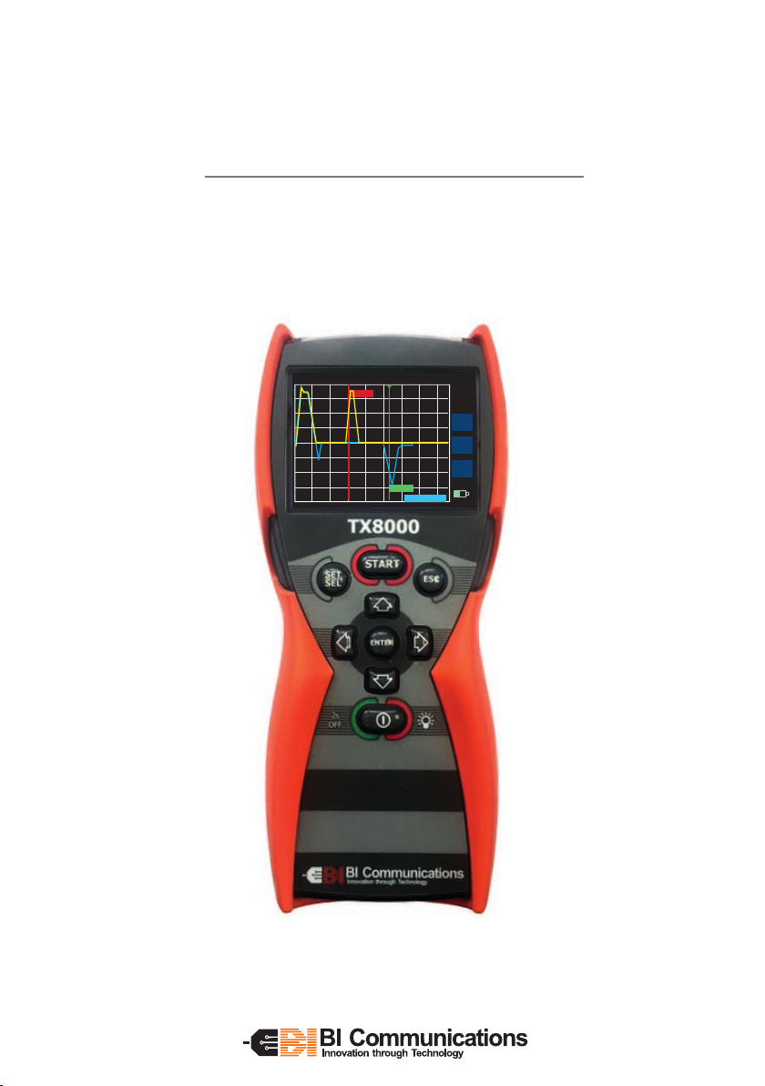
TX8000
Operating Instructions
Version 1.1
Z = 50Ω VoP= 67 %Vc RANGE = 120m
CONT
CUR
C1 2
GAIN
X1
?
ALKA
11.75m
20.65m
C1 2: 8.90m
TH

2TX8000 Operating Instructions
Section 1 Notices
1.1 Receiving the TX8000........................................................ 3
1.2 Safety notices.................................................................... 3
1.3 Standards .......................................................................... 4
Section 2 Introducing the TX8000
2.1 TX8000 features................................................................. 5
2.2 Specifications.................................................................... 6
2.3 Accuracy ............................................................................ 7
Section 3 Initial preparation of TX8000
3.1 Fitting / replacing batteries .............................................. 8
3.2 Key pad functions ............................................................. 8
3.3 on/o functions................................................................. 9
3.4 Keypad backlight .............................................................. 9
Section 4 Preparing the TX8000 for use
4.1 Screen displays and menu.............................................. 10
4.2 Set Velocity of Propagation unit..................................... 11
4.3 Set length unit of measure ............................................. 11
4.4 Set display brightness..................................................... 11
4.5 Set auto shutdown.......................................................... 11
4.6 Set language.................................................................... 11
Section 5 Using the TX8000
5.1 Measurement display...................................................... 12
5.2 Setting cable parameters................................................ 13
5.3 Selecting range scales..................................................... 13
5.4 Selecting scan modes, Compare and tone generator ... 13
5.5 Use of cursors.................................................................. 13
5.6 Gain control..................................................................... 13
5.7 Connecting to a cable to be tested................................. 14
5.8 How to determine unknown VoP values........................ 14
5.9 Typical fault displays ...................................................... 15
Section 6 Maintenance
6.1 Fitting and changing batteries ....................................... 16
6.2 Cleaning........................................................................... 16
6.3 Storage............................................................................. 17
Section 7 Repair and warranty
7.1 Contacting Bi Communications Ltd .............................. 17
Contents
3
TX8000 Operating Instructions
International Electrical Symbols
This symbol signifies that the instrument is protected by double or
reinforced insulation. Use only specified replacement parts when
servicing the instrument.
This symbol on the instrument indicates a WARNING, and that the
operator must refer to the user manual for instructions before operating
the instrument. In this manual, the symbol preceding instructions
indicates that if the instructions are not followed, bodily injury,
installation/sample and product damage may result.
Risk of electric shock. The voltage of the parts marked with this symbol
may be dangerous.
Section 1 - Notices
1.1 Receiving the TX8000
Upon delivery of the TX8000, ensure the contents are consistent with the
packing list, notify your supplier of any missing items.
If the equipment appears damaged, notify your carrier and supplier
immediately, giving a detailed description of any damage, save the damaged
packaging to substantiate your claim.
The TX8000 Includes, 0.5 mtr test lead, shoulder/neck strap, screw driver, 4 x AA
batteries, protective case and Quick start instruction manual.
1.2 Safety Notices
• This instrument meets the safety requirements of IEC61010-1: 1995
• TheTX8000 is designed for use on de-energized circuits only.
• Connection to line voltages will damage the instrument and could be
hazardous to the operator
• This instrument is protected against connection to telecom network
voltages according to EN61326-1.
• Safety is the responsibility of the operator
WARNING

4TX8000 Operating Instructions
1.3 Standards
The TX8000 has been manufactured in accordance with BI Communications
ISO 9001-2015 quality system and meets with the following international
standards:
Safety IEC 61010-1
EN 60950
EMC BS/EN 61326-1
Water/ Dustproof to IP67
Section 2- Introducing the TX8000
The TX8000 is a 6 Km range Time Domain Reflectometer housed in a rugged
over moulded case being water proof to IP67 and drop resistant, designed for
outdoor use, but suiciently small and light weight for general use and may
be operated using one hand. Using a 3.5-inch QVGA colour display information
is clearly displayed; an illuminated keypad makes the TX8000 ideal for use in
poorly lit areas.
Using 11 range scales with a first range of 7 meters near end faults are clearly
visible. Using the scan hold function faults may be retained on screen for
closer examination or when in scan mode intermittent faults may be easily
identified. By using the trace hold and compare feature the current trace may
be displayed and compared with a new trace. The user variable gain function
allows small events on the wave form to be magnified for clearer identification.
With dual cursors each cursor giving its length measurement and a dierential
distance between cursors the length of the fault may be identified. To assist in
the identification of faults a number of fault types may be super imposed over
the displayed fault for easier identification.
5
TX8000 Operating Instructions
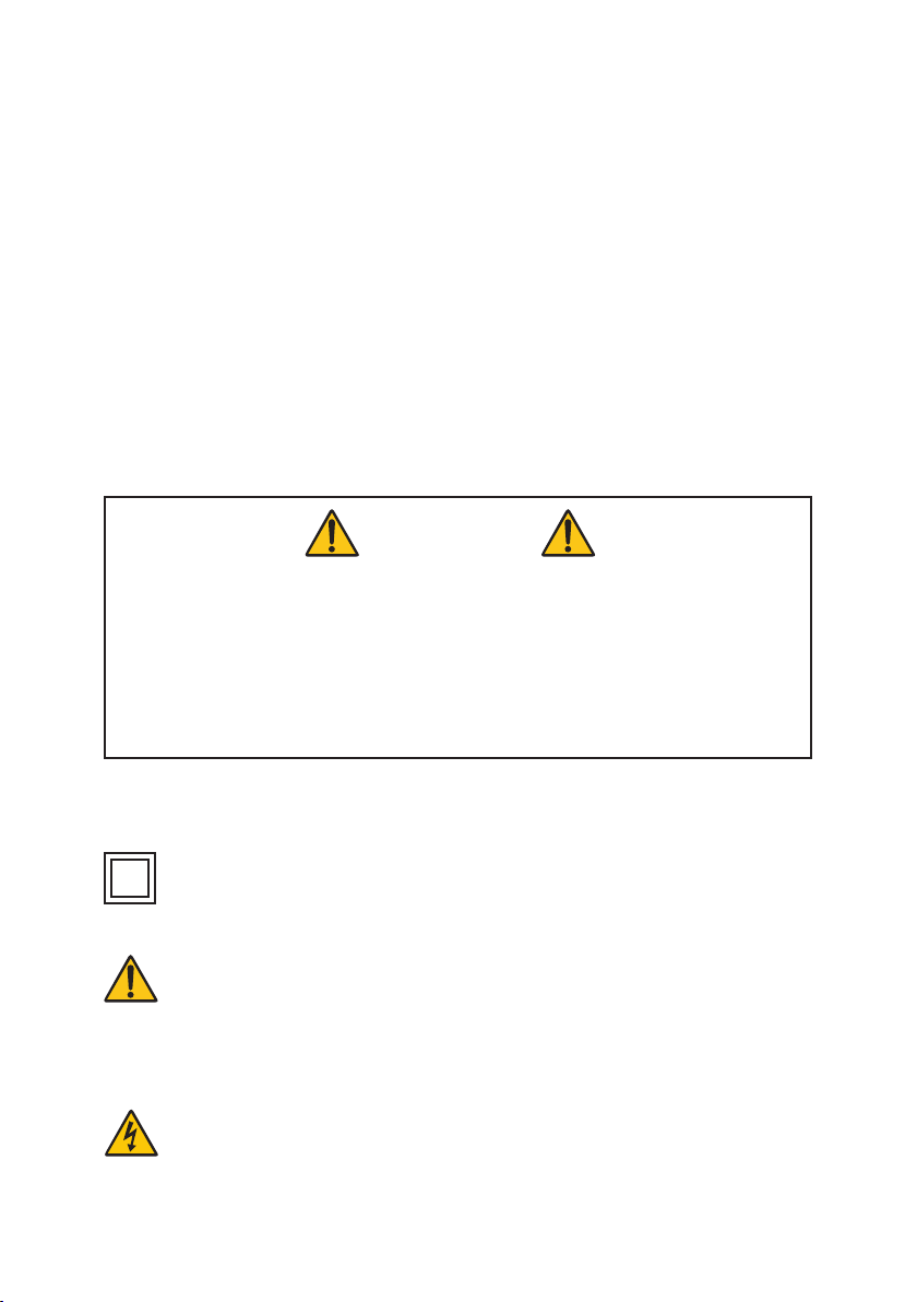
2.1 TX8000 features
Drop proof, Water/
dustproof to IP67
Dual cursors
Distance between
cursors
3.5” Colour
QVGA Display
Fault
indication
overlay
Illuminated
keypad
Over
moulded
case
Output via 2 x 4mm
Safety Sockets
Z= 75 . VoP+ 76 %Vc RANGE= 30m CONT
CUR
C1 2
GAIN
X1
?
ALKA
14.23m
20.65m
C1 2: 8.90m
Shorted Conductor

6TX8000 Operating Instructions
2.2 Specifications.
Ranges meters 7, 15, 30, 60, 120, 250, 500, 1km, 2km, 3km, 6km
Feet 23, 49, 98, 197, 394, 820, 1640, 3280, 6560, 9850, 19000
Range Selection Manual range control
Cursors Dual cursors with a distance measurement
between cursors
Accuracy 1% of selected range*
Resolution Approx. 1% of range
Sensitivity Min 3 pixel return at 4km on 0,6mm Æ , PE , TP
Velocity Factor Adjustable from 10% to 99% or equivalent
in Ft/ meters per micro second
Output Pulse 5 volts peak to peak. Into open circuit
Output Impedance 25, 50, 75, 100 & 120 ohms
Output pulse 3 ns to 3 us, Automatic with range
Scan Rate 2 scans / second or scan held
Tone Generator 810 – 1100Hz
Battery Life 7 hours typical use
Power Supply 6 volts, 4 x 1.5 AA Alkaline cells or NMH
rechargeable cells
Power Down 1, 2, 3, 5, 10 and 15 minutes or disabled
Display 328mm x256mm QVGA
Voltage protection 250 volts AC
Operating Temp -10º / 50ºC
Storage Temp -20º / 70ºC
Dimensions 220 x 98 x 58 mm / 8.7x3.8x2.3 inches
Weight 0.5 Kg / 1pouind 2 ounces
Safety IEC 61010-1 EN 60950
EMC BS/EN 61326-1
Protection Class IP67
* Measurement accuracy of +/-1% assumes the instrument setting for VoP of
the cable under test to be accurately set, homogeneity of the VoP along the
cable length, and accurate cursor positioning.

7
TX8000 Operating Instructions
2.3 Accuracy
The TX8000 is able to measure distances to faults on cable lengths to an
accuracy of +/- 1%, this accuracy is based upon the correct value VoP being
selected and homogeneity of the VoP along the cable length. If the VoP varies
additional errors will be incurred which may aect the measurement accuracy.
NOTE: - The VoP is less well defined with unshielded multicore cables including
power cables and is lower when a cable is tightly wound on a drum than when
installed.
8TX8000 Operating Instructions
3.1 Fitting batteries
The TX8000 is supplied with 4 X AA 1.5-volt batteries. These will need to be
installed, please refer to section 6.1 for installation procedure. The TX8000 is
designed to accept AA size Alkaline cells or rechargeable NMH cells. Because
Alkaline and NMH cells discharge at dierent rates the battery condition indi-
cator is customised to accommodate each type, therefore the type of battery
fitted will need to be selected. The type of batteries fitted are displayed at (9)
and the battery status at (10) on the measurement screen, see section 5.1.
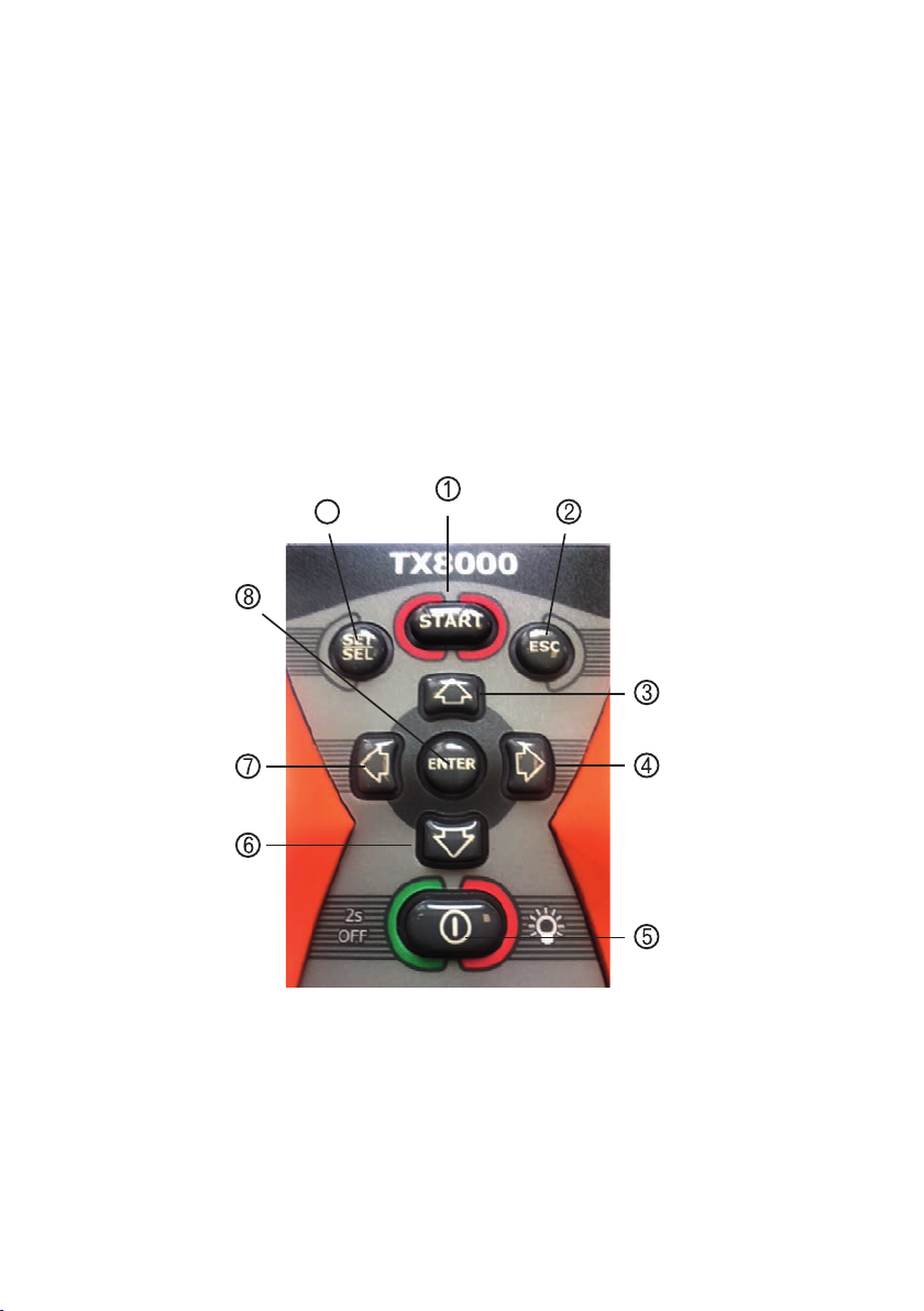
Section 3.2 Keypad functions.
Section 3 Initial preparation of TX8000
1. To commence trace / hold trace
2. Escape to exit TDR mode
3. Increase setting
4. Cursor right/Option
5. On/O and keyboard light
6. Decrease setting
7. Cursor le/Option
8. Enter to save selected
setting and select active
cursor
9. Set/Sel to select screen
options
9

9
TX8000 Operating Instructions
3.3 On/O functions
Upon compleon of item 3.1 press and release key (5), the start up
display will be shown momentarily and will be followed by the baery
selecon display below.
This display will only be shown when the batteries are removed or re-
placed. Follow the on-screen instructions to select battery type.
To turn o press and hold Key (5) until the display closes.
3.4 Key Pad Backlite
Upon switching on the TX8000 the key pad backlite will be turned on for 20
seconds, by pressing any key this will restart the illumination for 20 seconds.
The illumination may be turned On or O by momentarily pressing key (5). If
manually turned o it will not start automatically with a key press. The function
will return to automatic when the TX8000 is switched o and restarted.
Please Select Battery Type
1. ALKALINE
2. NIMH
Please Use UP/DOWN Arrow Keys
To Select Battery Type
Press ENTER to complete Selections

10 TX8000 Operating Instructions
Section 4 preparing the TX8000 for use
4.1 Screen displays and menus
11.75m
20.65m
C1 2: 8.90m
Please Select Battery Type
1. ALKALINE
2. NIMH
Please Use UP/DOWN Arrow Keys
To Select Battery Type
Press ENTER to complete Selections
TX 8000
V1
MEASUREMENTS
SETTINGS
HELP
1 VOP UNIT VP%
2 LENGTH UNIT METERS
3 BRIGHTNESS HIGH
4 AUTO SHUTDOWN 2mins
5 LANGUAGE ENGLISH
LIST of VoP AND
IMPEDANCE
VALUES
START-UP DISPLAY
MAIN MENU
MEASUREMENT DISPLAY SETTINGS MENU
HELP MENU
BATTERY SELECTION

11
TX8000 Operating Instructions
Using the keypad as shown in section 3.2 set the following parameters, use key
(9) to highlight the parameter and keys (3) and (6) to change values
4.2 Set Velocity of Propagation (VoP) unit
VoP may be set as a % of the speed of light or a speed in feet or meters per
micro seconds, the unit of distance will be that selected in 4.3 below.
4.3 Set length unit of measure
The length unit of measure may be set in either feet or meters. When the length
unit has been selected this will automatically be transferred to the setting in
4.2 above.
4.4 Set display brightness
This is selectable between High, medium and low. The lowest possible setting
should be used suitable for the ambient light conditions to preserve battery life.
4.5 Auto shutdown
To preserve battery life the TX8000 is fitted with an auto shutdown feature,
shutdown time may be selected for 1,3,5,10 and 15 minutes or disabled. When
the TX8000 is set in tone mode (see section 5.4) the unit will default to disabled
to allow time for cable tracing.
4.6 Language support
The TX8000 may be set to the following languages English, German, Spanish,
Japanese and Polish.

12 TX8000 Operating Instructions
Section 5 Using the TX8000
Upon completion of the set-up procedures in section 4 press key (2) to return
to main menu and press (8) to select measurements the following display will
be shown
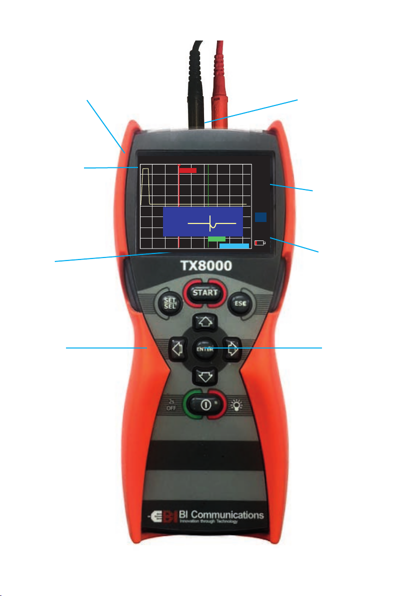
5.1 Measurement display
In sections 5.2 to 5.6, to change settings press key (9) to highlight parameter,
press keys (3) or (6) to select required value
1
13
1415
234 5 6
7
8
9
10
11
12
1 - Impedance value selected
2 - Cursor distance Red
3 - VoP value
4 - Active cursor
5 - VoP unit
6 - Range selected
7 - Trace hold
8 - Scan Mode or Tone
9 - Cursor option selected
10 - Gain value selected
11 - Fault display overlay
12 - Battery type selected
13 - Battery condition indicator
14 - Distance between cursors
15-Cursor distance green
Z = 50Ω VoP= 67 %Vc RANGE = 120m
CONT
CUR
C1 2
GAIN
X1
?
ALKA
20.65m
C1 2: 8.90m
TH
11.75m

13
TX8000 Operating Instructions
Section 5.2 Setting cable parameters
Impedance setting is selectable for 25,50, 75, 100 or 120 ohms. VoP values are
selectable between 10 and 99% or an equivalent value in feet or meters per
micro second. The values selected are shown on the display at (1), (2) and (3)
Values for both impedance and VoP are shown in the help menu. If the cable
required is not shown the cable manufacturer may be contacted for details or
the VoP may be established from a sample length of the cable to be tested (see
section 5.8)
Section 5.3 Range selection
The TX8000 has 11 range scales between 7 meters and 6 kilometres or the
equivalent values in Feet. The range selected is shown on the display (4)
Section 5.4 Scan modes, Compare and Tone generator
The TX8000 has three scanning modes, single and continuous scan. single scan
allows the user to hold the trace for closer examination and disconnect from
the cable being tested whilst leaving the trace displayed, to commence a trace
press key 1. Continuous scan fires continuous pulses into the cable under test
thus enabling intermittent faults to be identified. When in continuous scan
mode the trace displayed may be held by pressing START (key 1), TH will be
displayed in the top right of the display, the trace will be held and may be
compared with a new trace, to delete held trace press START (key1). The held
trace will automatically be deleted if the TX8000 is switched o.
Tone Generator, this function is used to trace individual pairs within the cable.
The TX8000 is connected to the cable pair being traced and using an industry
standard tone probe in the frequency range of 810 to 1100Hz the probe will
identify the pair, the volume will increase the nearer the probe is to the pair
being traced. Auto shutdown is disabled whilst this function is being used.
The function selected is shown on the display (5)
Section 5.5 Cursors
The TX8000 has dual cursors, cursor 1 Red and cursor 2 Green, to alternate
between cursors press key (8), the cursor selected is identified by the arrow
on the top of the cursor, as shown (14) on the display. To move the cursor use
keys 7 and 4. The length measurement is displayed on the flag attached to the
cursor as shown on the display (12) and (13). The distance between cursors is
shown on the display (11)
14 TX8000 Operating Instructions
Section 5.6 Gain
The TX8000 has a pre-set gain for each of its 11 range scales, there is in addition
8 user selectable values to assist in the identification of small impedance miss
matches. The gain value selected is shown on the display (7)
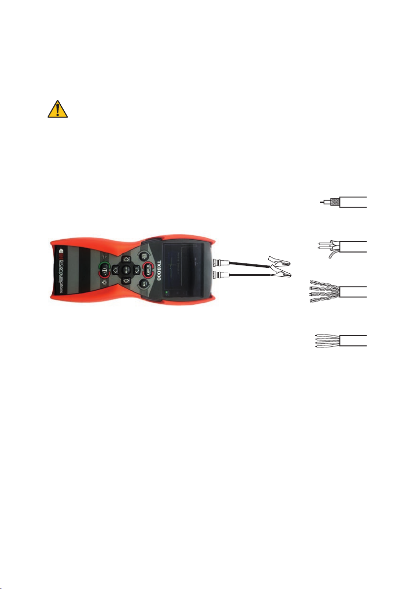
5.7 connecting the TX8000 to a cable to be tested
Attach the test lead set to the TX4000 via the 2 safety sockets
located at the top of the unit,
1. Ensure that no power supply or equipment is attached to the
cable to be tested
2. Ensure that the far end of the cable under test is open or
Shorted (not fitted with a resistive termination)
3. Attach the TX8000 to one end of the cable to be tested
Coaxial Cable: Connect the red clip to the centre wire and the black clip to the
shield/screen.
Shielded Cable: Connect the red clip to a wire adjacent to the shield and the
black clip to the shield.
Twisted Pair: Separate out one pair and connect the red and black clips to the
two wires of the pair.
Multicore Cable: Connect the clips to any two wires.
5.8 How to determine VoP value from a sample cable
Using a measured length of cable approximately 100 meters of the type to
be tested, connect the TX8000 as shown 5.8 above, select a range scale that
will cover the length of the sample cable, align the cursor to the rising edge
of the output pulse, (the correct positioning of the cursor is shown In typical
fault traces label on the rear of the TX8000 or may be displayed on screen by
CoaxialC able
Shielded Cable
TwistedP air
Multi-conductorC able
15
TX8000 Operating Instructions
selecting ?), select VoP, change the VoP setting until the length shown on
the cursor flag equals the length of the sample. The VoP shown will be the
VoP for the sample cable.
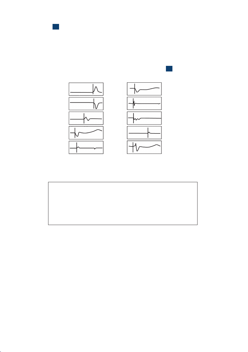
5.9 Typical fault displays
The following diagrams show typical fault traces, these faults may be
superimposed on the measurement screen by selecting ?on the screen.
Typical Cable V.P and Impedance Values
4.12 Typical Fault Displays
The following diagrams show typical fault traces to assist you in the
identification of faults using the TX4000:
OPEN
CONDUCTOR
SHORTED
CONDUCTOR
SPLICE
BRIDGE TAP
SPLIT/
RESPLIT
WET SPLICE/
WATER
FRAYED
CABLE
WATER
INGRESS
TAP
SPLITTER
4.13 Typical Cable V.P and Impedance Values
Type Vp Z Type Vp Z
Cat5 STP 72 100 T/Pair Jelly PE 64 100
Cat5 UTP 70 100 T/Pair PE 67 100
Coax Air 98 50/75 T/Pair PTFE 71 100
Coax Air Space 94 50/75 T/Pair PVC 58 100
Coax Foam PE 82 50/75 T/Pair Paper 72nF 88 100
Coax Solid PE 67 50/75 T/Pair Paper 83nF 72 100
15

16 TX8000 Operating Instructions
Section 6 Maintenance
6.1 Fitting and changing batteries.
Disconnect the TX8000 from any cable or
network link Turn the TX8000 o
• Loosen the 4 black screws and remove the battery compartment cover.
• Replace the batteries with 4 x 1.5 Alkaline or NMH AA size batteries
observing the polarities
• Refit the battery compartment cover and refit the 4 screws.
• Refer to section 3.3 for switching on procedures.
6.2 Cleaning
Disconnect the instrument from any source of electricity
• Turn the instrument o
• Use a so cloth lightly dampened with soapy water, wipe over
the instrument, rinse the cloth in clean water squeezing out
any excess water, wipe over the instrument removing any soap
residue, dry instrument with a dry cloth
• Do not splash water directly on the instrument
• Do not use alcohol, solvents or hydrocarbons

17
TX8000 Operating Instructions
6.3 Storage
If the instrument is not to be used for a period of more than 60
days, it is recommended that the batteries are removed and stored
separately (see 6.1)
Section 7 Repair and Warranty
The instrument contains static sensitive devices and is not user serviceable. If
an instrument fails, or its protection has been impaired, it should not be used
but sent back for repair by suitably trained and qualified personnel.
New instruments are guaranteed against breakdown due to manufacturing or
component defects for 36 months aer the purchase date by the user.
NOTE: Any unauthorized prior repair or adjustment to the instrument will
automatically invalidate the warranty.
The quality management system of BI Communications fulfils the
stringent requirements of the international quality system ISO 9001-2015.
7.1 Contacting Us
BI Communications Ltd
Unit 7 Buckwins Square
Burnt Mills Ind. Estate
Basildon
Essex
SS13 1BJ
UK
Tel: +44 (0)1268 729393
Fax: +44 (0)1268 727987
Email: sales@bicommunications.co.uk
Web: www.bicommunications.co.UK

Other manuals for TX8000
1
This manual suits for next models
1
Table of contents
Other BI COMMUNICATIONS Measuring Instrument manuals

Popular Measuring Instrument manuals by other brands

AutomationDirect
AutomationDirect ProSense DPM1 Series user manual

Dynalab
Dynalab MTH-103E Installation and operation manual

B+K precision
B+K precision 177/V-95 instruction manual

B+K precision
B+K precision 8550 Series user manual

Promax
Promax 6 manual

Aqua Medic
Aqua Medic T Controller HC Operation manual


red lion
red lion CUB 5V Series installation guide

Securitytronix
Securitytronix ST-EZ4 quick start guide

red lion
red lion PAXLR-PAX quick start guide

VPInstruments
VPInstruments VPLog-i-R user manual

Check-line
Check-line CDT-2000 operating instructions

Applied Instruments
Applied Instruments T12 LO-11300 Application note