7
Architect's & Engineer's Specifications
AUDIA®Digital Audio Platform
ARCHITECT'S & ENGINEER'S SPECIFICATION
The Digital Audio Platform shall be available in three hardware
configurations: 8-in/8-out (8x8); 12-in/4-out (12x4); and 4-in/12-out (4x12).
Inputs and outputs shall be analog, with internal 24-bit A/D & D/A converters
operating at a sample rate of 48kHz. All internal processing shall be digital
(DSP). Electronically balanced inputs and outputs shall be provided on plug-in
barrier-strip connectors. Inputs shall be individually programmable to accept
either microphone or line level signals. The 12x4 configuration shall allow
inputs 11 & 12 to be set for mono summing of unbalanced stereo line level
signals. Outputs shall normally provide line level signals, however, the 4x12
configuration shall allow outputs 1~4 to be individually programmed to provide
microphone level signals.
Each hardware configuration shall include six 60MHz 32-bit floating point
SHARC DSPs, an 80MHz 32-bit Power PC host processor, 32MB SDRAM, and 8MB Flash
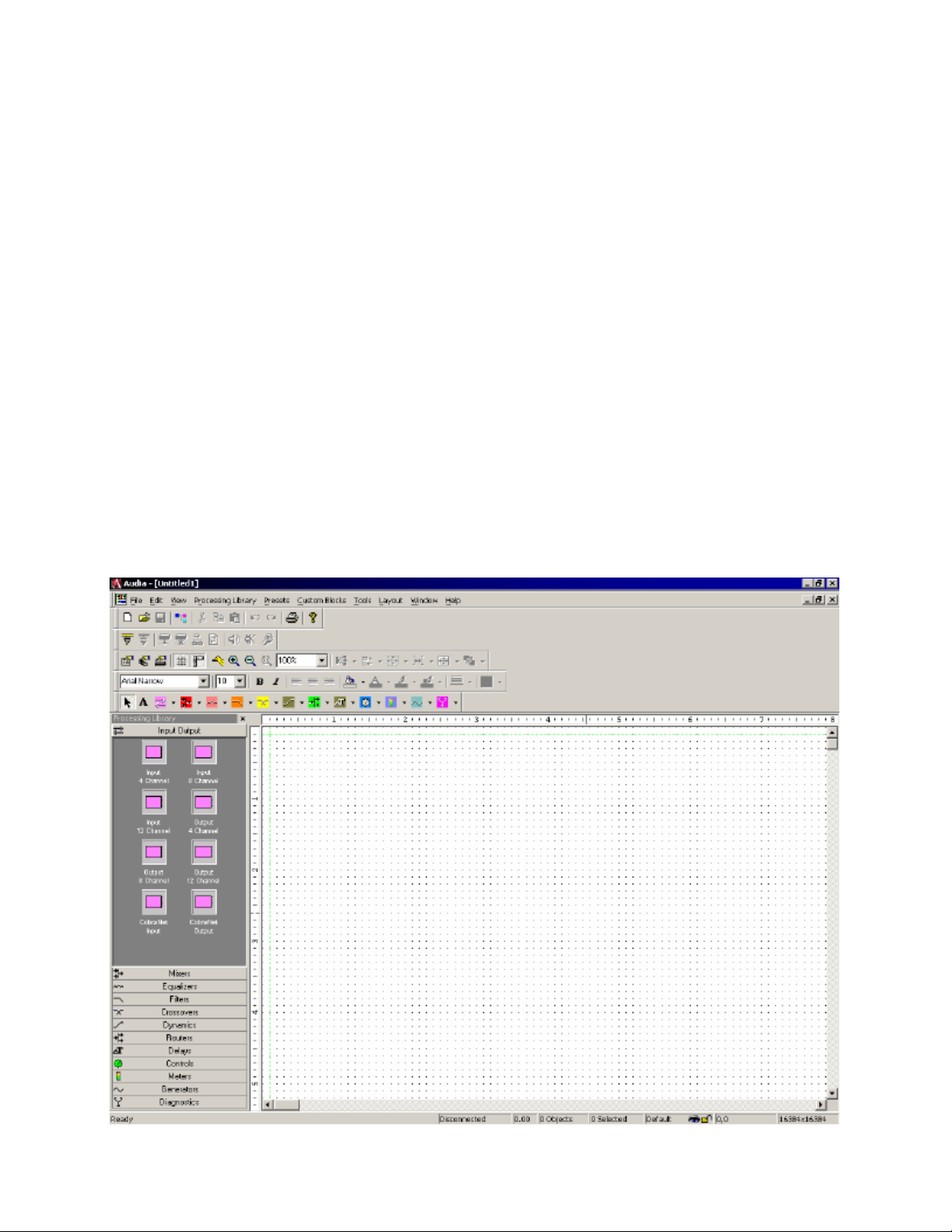
ROM. Software shall be provided for creating/connecting DSP system components
within each hardware unit. Available system components shall include (but not
be limited to) various forms of: mixers, equalizers, filters, crossovers,
dynamics/gain controls, routers, delays, level controls, level meters, and tone
generators. Ethernet communications shall be utilized for software control,
configuration, and DSP sharing. CobraNet™ technology shall transport digital
audio over fast Ethernet, allowing multiple units to share digital audio. After
initial programming, systems may be controlled using either TCP/IP or RS-232
serial communication by third party control systems such as AMX®and Crestron®.
Each hardware configuration shall be available with CobraNet™ (for multi-unit
network applications) or without CobraNet™ (for stand-alone applications).
Multi-unit network applications require an external 10/100Base-T Ethernet
switch. All CobraNet™ & Ethernet connections shall be via CAT5 cable or fiber-
optic. Software shall operate on a PC computer, with network card installed,
running Windows®2000/XP.
The Digital Audio Platform shall be AUDIA®.
AudiaSOLO Digital Audio Platform
ARCHITECT'S & ENGINEER'S SPECIFICATION
The Digital Audio Platform shall be available in three hardware
configurations: 8-in/8-out (8x8); 12-in/4-out (12x4); and 4-in/12-out (4x12).
Inputs and outputs shall be analog, with internal 24-bit A/D & D/A converters
operating at a sample rate of 48kHz. All internal processing shall be digital
(DSP). Electronically balanced inputs and outputs shall be provided on plug-in
barrier-strip connectors. Inputs shall be individually programmable to accept
either microphone or line level signals. The 12x4 configuration shall allow
inputs 11 & 12 to be set for mono summing of unbalanced stereo line level
signals. Outputs shall normally provide line level signals, however, the 4x12
configuration shall allow outputs 1~4 to be individually programmed to provide
microphone level signals.
Each hardware configuration shall include six 60MHz 32-bit floating point
DSPs, an 80MHz 32-bit host processor, 32MB SDRAM, and 8MB Flash ROM. Software
shall be provided for creating/connecting DSP system components within each
hardware unit. Available system components shall include (but not be limited
to) various forms of: mixers, equalizers, filters, crossovers, dynamics/gain
controls, routers, delays, remote controls, meters, generators, and diagnostics.
Ethernet communications shall be utilized for software control and
configuration. After initial programming, systems may be controlled using
either TCP/IP or RS-232 serial communication by third party control systems
(such as AMX®and Crestron®), by PC computer, and/or by dedicated remote control
devices. Software shall operate on a PC computer, with network card installed,
running Windows® 2000/XP.
The Digital Audio Platform shall be AudiaSOLO.