BIAX BP 3-10 Operational manual
BA-NR.: 001 580 343 Stand 22.04.2014
Originalbetriebsanleitung
Translation of the original operating manual
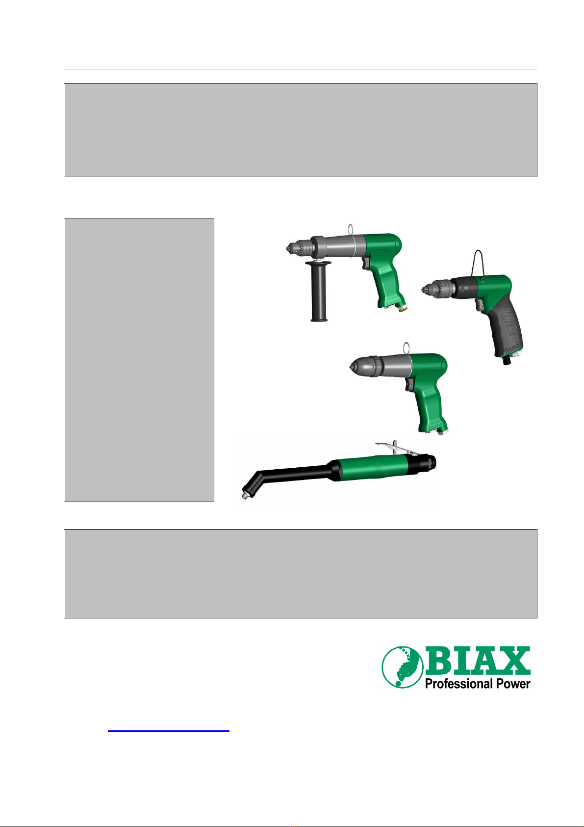
Druckluftbohrmaschinen
Pneumatic Drills
BP 3-10
BP 0,5-10
BP 500
BP 800
BP 1000
BP 2600
BP 4500
BP 6000
BWH 6-25/2 K90
BWH 6-25/2 K45
Diese Anleitung muss dem Anwender (Werker) ausgehändigt werden!
A copy of this manual must be given to all personnel working with this tool!
Schmid und Wezel GmbH & Co.
KG
Maschinenfabrik
Maybachstraße 2
D -75433 Maulbronn
Telefon: 07043 / 102-0
Telefax: 07043 / 102-78
E-Mail:
Webadresse: www.biax.de

Betriebsanleitung für
Druckluft-Bohrmaschinen
BA-NR.: 001 580 343 2 von 11
Stand 22.04.2014
Technische Daten
Typ
Drehzahl
Max. Spann-Ø
Leistung
Luftverbauch
Schalldruck-
pegel
Schallnorm
Vibration
Vibrationsnorm
Anschluss-
gewinde
Schlauchweite
Gewicht
1/min
mm
W l/min
dB(A) m/s² mm kg
BP 0,5-10 500 10 220
450
77 - < 2,5 ISO 2886-3 G 1/4 7 1,7
BP 3-10 3000 10 250
450
78 - < 2,5 ISO 2886-3 G 1/8 7 1,25
BP 500 500 8 160
450
72 / K=3
ISO 15744 < 2,5 ISO 28927-5 G 1/8 7 0,74
BP 800 800 8 160
450
72 / K=3
ISO 15744 4,3 K=0,73 ISO 28927-5 G 1/8 7 0,74
BP 1000 1000 8 160
450
74 / K=3
ISO 15744 6,0 K=2,0 ISO 28927-5 G 1/8 7 0,74
BP 2600 2600 8 160
450
75 / K=3
ISO 15744 3,1 K=1,0 ISO 28927-5 G 1/8 7 0,7
BP 4500 4500 8 160
450
74 / K=3
ISO 15744 3,1 K=1,0 ISO 28927-5 G 1/8 7 0,7
BP 6000 6000 8 160
450
74 / K=3
ISO 15744 5,2 K=1,2 ISO 28927-5 G 1/8 7 0,7
BWH 6-25/2 K90
2500 6 200
500
75 - 5,2 K=1,1 ISO 28927-5 G 1/8 7 1,22
BWH 6-25/2 K45
2500 6 200
500
75 - 7,5 K=2,1 ISO 28927-5 G 1/8 7 1,24
Allgemeine Hinweise
Diese Betriebsanleitung ist Bestandteil des Liefer-
umfangs. Sie ist in leserlichem Zustand in Zugriffs-
nähe bereitzuhalten und bleibt auch bei Weiterverkauf
des Gerätes beim Gerät.
Diese Betriebsanleitung richtet sich an eingewiesenes
und autorisiertes Fachpersonal.
Änderungen durch technische Weiterentwicklungen
gegenüber den in dieser Betriebsanleitung darge-
stellten Ausführungen behalten wir uns vor.
Nachdrucke, Übersetzungen und Vervielfältigungen in
jeglicher Form, auch auszugsweise, bedürfen der
schriftlichen Zustimmung des Herausgebers.
Das Urheberrecht liegt beim Hersteller.
Verantwortlichkeit des Betreibers
Der Betreiber hat die geltenden nationalen Unfall-
verhütungsvorschriften und technischen Regeln
einzuhalten.
Der Betreiber darf das Gerät nur von geschultem und
zuverlässigem Personal bedienen lassen.
Der Betreiber hat dafür Sorge zu tragen, dass die
Bediener die Betriebsanleitung gelesen und verstan-
den haben, bevor sie das Gerät bedienen.
Der Betreiber hat dafür zu sorgen, dass kein Unbe-
fugter an das Gerät gelangen und dieses nutzen
kann.
Die innerbetrieblichen Arbeitsschutzvorschriften sind
zu beachten.
Bestimmungsgemäße Verwendung
Die Druckluft-Bohrmaschinen – im weiteren Bohr-
maschinen genannt – dürfen nur als handgehaltene
Maschinen zum
•Bohren
•Bürsten und
•Entgraten
von Bohrungen verwendet werden.
Jeglicher Missbrauch der BIAX Druckluft-Bohr-
maschinen außerhalb der oben genannten
Einsatzgebiete sowie bauliche Veränderung der
Maschinen ist ohne Zustimmung durch Schmid &
Wezel nicht zulässig. Bei Zuwiderhandlung entfällt
jegliche Haftung für Folgeschäden.
Beachten Sie beim Betrieb der Bohrmaschinen die
DIN EN ISO 11148-3.
Die vorgeschriebenen Drehzahlen, Aufspannlängen
und die Mindest - Einspannlänge von 10 mm müssen
eingehalten werden.
Sicherheit
Sicherheitskennzeichnung
Folgende Signalwörter werden in Verbindung mit
Sicherheitszeichen zur Darstellung möglicher
Gefahren in diesem Dokument verwendet:
Betriebsanleitung für
Druckluft-Bohrmaschinen
BA-NR.: 001 580 343 3 von 11
Stand 22.04.2014
Gefahr!
Tod, schwere Körperverletzung
oder erheblicher Sachschaden
werden eintreten, wenn die
entsprechenden Vorsichtsmaß-
nahmen nicht getroffen werden!
Warnung!
Tod, schwere Körperverletzung
oder erheblicher Sachschaden
können eintreten, wenn die
entsprechenden Vorsichtsmaß-
nahmen nicht getroffen werden!
Vorsicht!
Leichte Körperverletzung kann
eintreten, wenn die entsprechenden
Vorsichtsmaßnahmen nicht
getroffen werden!
Achtung!
Sachschaden kann eintreten, wenn
die entsprechenden Vorsichtsmaß-
nahmen nicht getroffen werden!
Sicherheitshinweise
Warnung!
Bei Nichtbeachtung der Sicher-
heitshinweise besteht akute
Verletzungsgefahr!
Beim Betrieb der Bohrmaschine
können Späne und eventuell
Funken die Augen verletzen.
Tragen Sie bei der Arbeit immer
eine Schutzbrille!
Je nach Art der Bearbeitung kann
der angegebene Geräuschpegel
überschritten werden.
Verwenden Sie einen Gehörschutz!
Arbeiten Sie bei Staubentwicklung
nur mit Atemschutz und schalten
Sie die Staubabsaugung an Ihrem
Arbeitsplatz ein!
Verletzungsgefahr durch scharf-
kantige Werkstücke!
Tragen Sie bei der Arbeit ggf.
passende Schutzhandschuhe!
Gesundheit
Vorsicht!
Vibration kann auf den ganzen
Körper, speziell auf Arme und
Hände, übertragen werden.
Sehr starke sowie andauernde
Vibration kann Nerven- und
Gefäßstörungen verursachen!
Vibrationen sind schädlich für Hände und Arme.
Reduzieren Sie die Zeit, in der Sie Vibrationen aus-
gesetzt sind. Beenden Sie sofort die Arbeit, wenn Sie
in den Händen Schmerzen, Kribbeln o. ä. Symptome
verspüren. Suchen Sie einen Arzt auf.
Kleidung, Schmuck, Haare u. ä. können durch rotie-
rende Teile der Bohrmaschine erfasst werden und zu
schweren Verletzungen führen.
Tragen Sie während der Arbeit nur enganliegende
Kleidungsstücke. Nehmen Sie Schmuck vor Arbeits-
beginn ab. Verwenden Sie bei langen Haaren
unbedingt ein Haarnetz!
Umgang mit der Bohrmaschine
Die Betriebsanleitung richtet sich
an eingewiesenes Fachpersonal!
Nichtbeachten der Betriebsan-
leitung kann zu Personenschäden
und Geräteausfällen führen!
Einzugsgefahr!
Während der Arbeit nur enganlie-
gende Kleidung tragen.
Nehmen Sie Schmuck vor
Arbeitsbeginn ab. Verwenden Sie
bei langen Haaren unbedingt ein
Haarnetz!
Verletzungsgefahr!
Das eingeschaltete Werkzeug ist
vom Körper weg zu halten!
Nicht in laufendes Werkzeug
greifen!
Werkzeug vorsichtig handhaben!
Explosionsgefahr!
Die Bohrmaschine darf in
explosionsgefährdeten Bereichen
nicht eingesetzt werden!
Warnung!
Beachten Sie nachfolgende
zusätzliche Hinweise zum
Umgang mit der Bohrmaschine
und dem Zubehör.
Ein Missachten der Hinweise
kann zu schweren und
schwersten Verletzungen führen!
Die Bohrmaschine darf nur in einwandfreiem,
funktionstüchtigem Zustand betrieben werden.
Prüfen Sie vor Arbeitsbeginn und nach jeder Unter-
brechung die Bohrmaschine, das Werkzeug und den
Druckluftschlauch auf Beschädigungen. Kontrollieren
Sie den festen Sitz des Werkzeugs in der Spann-
zange!
Vermeiden Sie beim und nach dem Betrieb direkten
Kontakt mit dem Werkzeug. Es ist heiß und
scharfkantig – Sie könnten sich verletzen.
Schließen Sie die Druckluftleitung nur mit einge-
spanntem Werkzeug und bei ausgeschaltetem Ventil
an!
Betriebsanleitung für
Druckluft-Bohrmaschinen
BA-NR.: 001 580 343 4 von 11
Stand 22.04.2014
Trennen Sie bei Werkzeugwechsel und Wartungs-
arbeiten die Bohrmaschine immer vom Druckluftnetz!
Der Fließdruck von 6 bar darf während des Betriebs
nicht überschritten werden!
Bei Unterbrechung der Luftzufuhr schalten Sie die
Bohrmaschine sofort aus!
Das Bohrfutter bzw. die Spindel läuft nach dem
Ausschalten noch nach. Legen Sie die Bohrmaschine
erst bei Stillstand des Werkzeugs ab!
Sichern Sie das Werkstück mit einer Spannvor-
richtung oder einem Schraubstock!
Beachten Sie, dass im Schlauch gespeicherte
Druckluft einen unerwarteten Start der Bohrmaschine
verursachen kann!
Verwenden Sie die Bohrmaschine nur mit unbeschä-
digtem Schlauch. Prüfen Sie die Schläuche und
Anschlüsse vor Arbeitsbeginn auf Beschädigungen.
Beachten Sie die Gefahr eines schlagenden Druck-
luftschlauches!
Richten Sie den Luftstrom niemals auf sich oder
andere Personen.
Beim Bohren können hohe Reaktionsdrehmomente
oder unerwartete Bewegungen der Bohrmaschine
auftreten verursacht durch
•Durchbrechen des Bohrers durch das zu bearbei-
tende Material
•Blockieren des Bohrers
Stellen Sie durch eine geeignete Arbeitshaltung
sicher, dass Sie beim Auftreten von Reaktions-
drehmomenten die Bohrmaschine sicher beherrschen
können und nicht das Gleichgewicht verlieren.
Halten Sie Maschinen, die einen zweiten Handgriff
haben, mit beiden Händen, um plötzlich auftretenden
Momenten entgegenwirken zu können.
Die Mindesteinspannlänge der Werkzeuge muss ein-
gehalten werden.
Verhalten am Arbeitsplatz
Halten Sie Ihren Arbeitsplatz in Ordnung!
Arbeiten Sie aufmerksam! Benutzen Sie das Gerät
nicht, wenn Sie müde sind oder unter dem Einfluss
von Alkohol, Drogen oder Medikamenten stehen!
Beim Betrieb der Bohrmaschine entstehen heiße
Späne und eventuell Funken. Entfernen Sie brenn-
bare Gegenstände und Materialien aus dem Arbeits-
bereich!
Konzentrieren Sie sich auf Ihre Arbeit und halten Sie
andere Personen von Ihrem Arbeitsbereich fern!
Bewahren Sie Ihre Werkzeuge sicher auf und pflegen
Sie diese sorgfältig!
Reparaturen dürfen nur von autorisiertem Fach-
personal durchgeführt werden.
Sorgen Sie für gute Beleuchtung und Belüftung des
Arbeitsplatzes.
Es wird empfohlen, eine Atemschutzmaske mit
Filterklasse P2 zu tragen. Außerdem sollten Sie
Handschuhe und Schutzkleidung tragen.
Verhalten bei Unfällen
Informieren Sie sich routinemäßig in regelmäßigen
Abständen, welche Möglichkeiten für die Erste Hilfe
zur Verfügung stehen!
Informieren Sie – nach der Erstversorgung von
Verletzten – bei Unfällen mit Personen-, Geräte- oder
Gebäudeschäden unverzüglich Ihren Vorgesetzten!
Verlassen Sie im Katastrophenfall (Brand) unver-
züglich die Bohrmaschine!
Benutzen Sie nur die gekennzeichneten Flucht-
einrichtungen und Rettungswege. Benutzen Sie keine
Aufzüge!
Nennen Sie für den gezielten Einsatz von Rettungs-
fahrzeugen den Schweregrad der Personen- und
Sachschäden!
Transport
Halten Sie die Bohrmaschine beim Transport am
Handgriff oder am Gehäuse.
Tragen Sie die Bohrmaschine niemals am Druck-
luftschlauch.
Anschluss und Inbetriebnahme
Vorsicht!
Schließen Sie die Bohrmaschine
nur bei eingespanntem Werkzeug
und ausgeschaltetem Ventil an das
Druckluftnetz an!
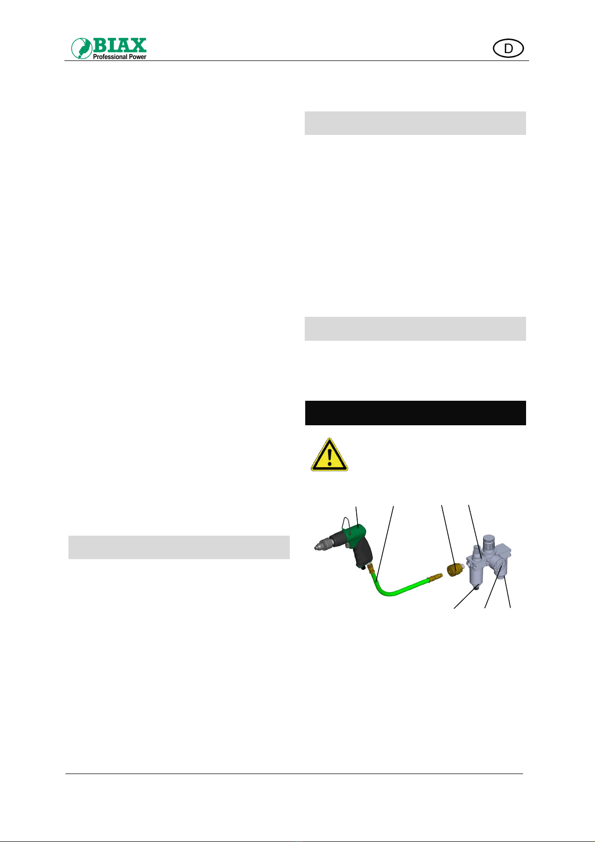
Abb. 1. Anschluss an die Druckluftversorgung
Druckschlauch vor dem Anschluss durchblasen, um
Verunreinigungen zu entfernen!
Wartungseinheit (Pos. D) in folgender Reihenfolge
montieren:
Wasserabscheider/Filter mit einer Filterfeinheit von
min. 40 µm (Pos. D1) – Druckregler (Pos. D2) –
Ölnebler (Pos. D3).
An der Wartungseinheit einen Betriebsdruck von max.
6 bar einstellen. Ölstand kontrollieren und ggf. Öl
nachfüllen.
A B C D
D3 D2 D1
Betriebsanleitung für
Druckluft-Bohrmaschinen
BA-NR.: 001 580 343 5 von 11
Stand 22.04.2014
Die Wartungseinheit so einstellen, dass der Luft
2 - 3 Tropfen Öl pro Minute beigemischt werden.
Die Bohrmaschine (Pos. A) mit einer Schlaucheinheit
(Pos. B) über eine Einhandkupplung (Pos. C) an die
Wartungseinheit (Pos. D) anschließen.
Handhabung
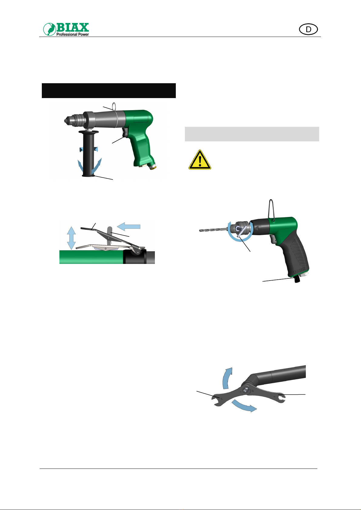
Abb. 2. Handhabung der Bohrmaschine
Ein- und Ausschalten (bei Typ BP)
Zum Einschalten Ventilknopf (Pos. F) drücken.
Zum Ausschalten Ventilknopf loslassen.(Siehe Abb. 2)
Abb. 3. Entsichern und Ein/Ausschalten Hebelventil
Ein- und Ausschalten (bei Typ BWH)
Zum Starten der Maschine den Hebel (H) in
Pfeilrichtung drücken, um Ventilhebel (I) zu entsichern
(siehe Abb. 3). Ventilhebel (I) in Pfeilrichtung EIN
drücken. Maschine ist in Betrieb, solange Ventilhebel
(I) gedrückt gehalten wird. Zum Ausschalten
Ventilhebel (I) loslassen. Hebel (H) rastet ein,
Ventilhebel (I) ist gesichert.
Zweiter Handgriff
Die Bohrmaschine BP 0,5-10 ist mit einem zweiten
Handgriff (Pos. G) ausgestattet. Halten Sie die Bohr-
maschine mit beiden Händen, um plötzlich auftre-
tenden Drehmomenten entgegenwirken zu können.
Verstellen des Handgriffs:
Handgriff (Pos. G) durch Drehen in Pfeilrichtung
„Lösen“ losdrehen und in gewünschte Position
schwenken.
Handgriff in Pfeilrichtung „Anziehen“ gut festziehen.
Aufhängung (bei Typ BP)
Die Bohrmaschine kann mit der Aufhängung (Pos. E)
an einem Federzug befestigt werden. Die Befestigung
muss gesichert sein.
Abluftführung (siehe Abb. 4)
Bei den Maschinenvarianten BP 500, 800, 1000,
2600, 4500 und 6000 ist unten an der Bohrmaschine
eine drehbare Abluftöffnung (Pos. J) vorhanden.
Damit können Sie die Luftauslassrichtung je nach
Anwendung einstellen.
Ablegen der Bohrmaschine
Legen Sie die Bohrmaschine nach Abschluss der
Arbeiten auf einer sauberen Ablage ab.
So verhindern Sie, dass der Handgriff der Bohr-
maschine verschmutzt oder beschädigt wird.
Werkzeugwechsel
Vorsicht!
Trennen Sie vor jedem Werkzeug-
wechsel die Bohrmaschine vom
Druckluftanschluss!
Typ BP 0,5-10, BP 500, BP 800, BP 1000,
BP 2600, BP 4500, BP 6000
Abb. 4. Werkzeugwechsel bei Zahnkranzbohrfutter
•Mit dem Bohrfutterschlüssel (Pos. K) aus dem
Zubehör das Bohrfutter öffnen.
•Werkzeug sicher und möglichst weit in das
Bohrfutter einspannen!
•Mit dem Bohrfutterschlüssel das Bohrfutter wieder
schließen.
Typ BWH 6-25/2 K45 und BWH 6-25/2 K90
Abb. 5. Werkzeugwechsel bei Spannzange
•Bei Bohrmaschinen mit Spannzange wird der
Werkzeugwechsel mit den im Lieferumfang
enthaltenen Schlüsseln durchgeführt.
G
F
LösenAnziehen
Schwenken
E
Zu
K
Auf
J
Ein
Aus
H
L
M
Zu
Auf
I
Betriebsanleitung für
Druckluft-Bohrmaschinen
BA-NR.: 001 580 343 6 von 11
Stand 22.04.2014
•Mit Schlüssel (L) die Spindel festhalten und
die Spannzange mit dem zweiten Schlüssel
(M) öffnen oder schließen.
Lassen Sie keine Werkzeugschlüssel stecken!
Stellen Sie vor dem Einschalten sicher, dass Bohr-
futterschlüssel und Einstellwerkzeuge entfernt
wurden.
Typ BP 3-10
Abb. 6. Werkzeugwechsel bei Schnellspannfutter
•Den Ring (Pos. O) festhalten und durch
Verdrehen der Hülse (Pos. N) das Bohrfutter
öffnen oder schließen.
•Werkzeug sicher und möglichst weit in das
Bohrfutter einspannen!
Wartung
Vorsicht!
Trennen Sie vor dem Durchführen
von Wartungsarbeiten die
Bohrmaschine vom Druckluft-
anschluss!
Nach jeweils 300 Betriebsstunden muss das Getriebe-
fett erneuert werden.
Hierfür steht Ihnen unsere Serviceabteilung zur
Verfügung.
Bitte wenden Sie sich an die nächstgelegene
Vertragswerkstatt oder direkt an unser Stammhaus.
Überprüfung der Wartungseinheit
Folgende Tätigkeiten müssen vor Inbetriebnahme der
Bohrmaschine durchgeführt werden:
•Entfernen von Kondenswasser.
•Nachfüllen mit BIAX Spezial-Öl.
•Fließdruck prüfen
6 bar dürfen nicht überschritten werden.
Wartungseinheit
Über die Druckluftanlage gelieferte Luft ist meist
verunreinigt und mit Feuchtigkeit angereichert.
Deshalb muss zwischen Druckluftanlage und Bohr-
maschine eine Wartungseinheit geschaltet sein.
Die Wartungseinheit regelt den Betriebsdruck, reinigt
und entwässert die Druckluft und gewährleistet eine
einwandfreie Schmierung des Druckluftwerkzeugs.
Damit werden der Nutzen und die Lebensdauer der
Werkzeuge wesentlich erhöht.
Die für Ihre Bohrmaschine geeignete Wartungseinheit
und das Spezialöl können Sie aus unserem Katalog
auswählen.
Reparatur
Achtung!
Reparaturen dürfen nur von
Fachkräften vorgenommen werden!
Hierfür steht Ihnen unsere
Serviceabteilung zur Verfügung.
Nur Originalteile verwenden!
Bei nachlassender Leistung müssen die Rotor-
schieber ausgewechselt werden.
Wenden Sie sich bitte an die nächstgelegene
Vertragswerkstatt oder direkt an unser Stammhaus.
Die entsprechenden Ersatzteillisten können auf
Wunsch an die Fachwerkstätten ausgehändigt
werden. Dazu wenden Sie sich bitte an unseren
Vertrieb.
Entsorgung
Die Verpackung der Bohrmaschine besteht weit-
gehend aus recyclingfähigem Material. Entsorgen Sie
dieses umweltgerecht.
Werfen Sie die Bohrmaschine am Ende der Lebens-
zeit nicht in den normalen Müll. Erkundigen Sie sich
nach Möglichkeiten einer umwelt- und sachgerechten
Entsorgung.
Beachten Sie dabei die örtlichen und nationalen
Regelungen zur Entsorgung.
Zubehör
Für die Bohrmaschinen mit Zahnkranzbohrfutter und
Spannzange sind im Lieferumfang enthalten:
Schlüssel für den Werkzeugwechsel.
Sonderzubehör
Sonderzubehör finden Sie in unserem Katalog:
Einhandkupplungen mit Schlauchanschluss oder
Außengewinde, Druckluftarmaturen, Schlauch-
einheiten, Schlauchbalancer, Werkbankausrüstungen,
Wartungseinheiten.
Spezialöl finden Sie in unserem Katalog.
N O
Zu
Auf

Operating manual for
pneumatic drills
BA-NR.: 001 580 343 7 von 11
Stand 22.04.2014
Technical Data
Type
Speed
Max. clamping-
Ø
Power
Air consumption
Sound pressure
level
Sound standard
Vibration
Vibration in
accordance with
Connection
thread
Hose width
Weight
rpm mm
W l/min
dB(A) m/s² mm kg
BP 0,5-10 500 10 220
450
77 - < 2,5 ISO 2886-3 G 1/4 7 1,7
BP 3-10 3000 10 250
450
78 - < 2,5 ISO 2886-3 G 1/8 7 1,25
BP 500 500 8 160
450
72 / K=3
ISO 15744 < 2,5 ISO 28927-5 G 1/8 7 0,74
BP 800 800 8 160
450
72 / K=3
ISO 15744 4,3 K=0,73 ISO 28927-5 G 1/8 7 0,74
BP 1000 1000 8 160
450
74 / K=3
ISO 15744 6,0 K=2,0 ISO 28927-5 G 1/8 7 0,74
BP 2600 2600 8 160
450
75 / K=3
ISO 15744 3,1 K=1,0 ISO 28927-5 G 1/8 7 0,7
BP 4500 4500 8 160
450
74 / K=3
ISO 15744 3,1 K=1,0 ISO 28927-5 G 1/8 7 0,7
BP 6000 6000 8 160
450
74 / K=3
ISO 15744 5,2 K=1,2 ISO 28927-5 G 1/8 7 0,7
BWH 6-25/2 K90
2500 6 200
500
75 - 5,2 K=1,1 ISO 28927-5 G 1/8 7 1,22
BWH 6-25/2 K45
2500 6 200
500
75 - 7,5 K=2,1 ISO 28927-5 G 1/8 7 1,24
General instructions
This operating manual forms part of the scope of
delivery. It has to be kept within reach in a readable
state, and remains with the device when it is sold on.
This operating manual is intended for trained and
authorised staff.
We reserve the right to include any changes due to
further technical developments compared to the
explanations included in this operating manual.
Copies, translations and reproductions in any form,
even in its entirety or parts of it, require the written
consent of the manufacturer.
The manufacturer holds the copyright.
Obligations of the proprietor
The proprietor has to adhere to the applicable national
accident prevention regulations and the technical
rules.
The proprietor must ensure that the device is only
operated by trained and reliable staff.
The proprietor has to ensure that the operating
personnel have read and understood the operating
manual before they operate the device.
The proprietor has to ensure that no unauthorised
person has access to the device and can use it.
Company-internal health and safety regulations must
be observed.
Intended use
The pneumatic drills - hereinafter referred to as drills -
must only be used as hand-held machines for
•drilling
•brushing and
•deburring
of drilling holes.
Every abuse of BIAX pneumatic drills outside the
above mentioned areas of use as well as
constructional changes of the machine are not
permitted without the consent of Schmid & Wezel.
In case of non-compliance no liability is granted
for any subsequent damage.
Observe DIN EN ISO 11148-3 when operating the
drill.
The prescribed revolutions, clamping lengths and the
minimal clamping length of 10 mm must be observed.
Safety
Safety labels
The following signal words are used in connection with
safety signs to depict possible danger in this
document:
Operating manual for
pneumatic drills
BA-NR.: 001 580 343 8 von 11
Stand 22.04.2014
Danger!
Death, serious injury or significant
material damage occur if the
corresponding precautions are not
taken
Warning!
Death, serious physical injury or
significant material damage may
occur if the corresponding
precautions are not taken!
Caution!
Light physical injury can occur if
the corresponding precautions are
not taken!
Attention!
Material injury can occur if the
corresponding precautions are not
taken!
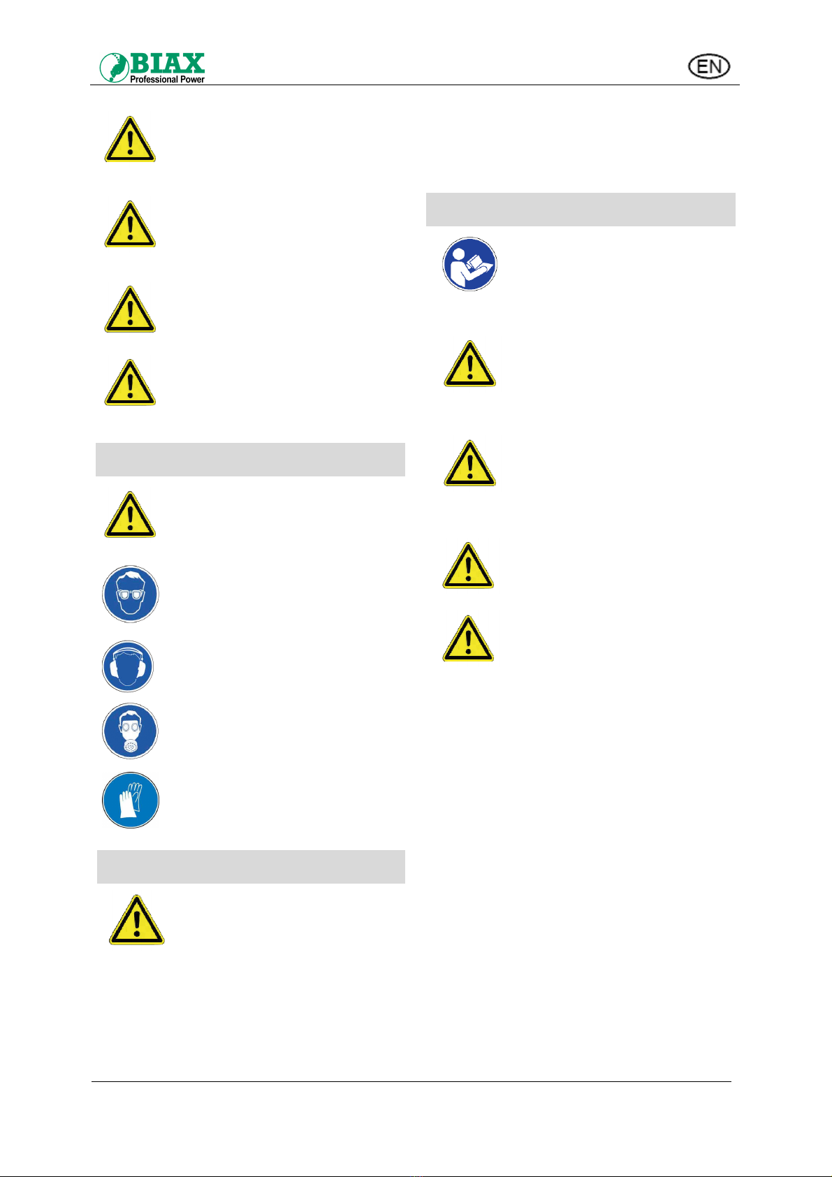
Safety notes
Warning!
If the safety notes are not adhered
to, there is a risk of injury.
When operating the drill chips and
possibly sparks may cause injury
to the eyes. Always wear safety
goggles at work!
Depending on the type of work the
indicated noise level can be
exceeded.
Use ear protection.
In case of dust only work with
breathing protection and switch on
the dust extraction at your
workplace!
Risk of injury by components with
sharp edges!
If necessary, wear safety gloves!
Health
Caution!
Vibration can be transferred to the
entire body, in particular to arms
and hands.
Very strong and continuous
vibration can cause damage to
nerves and blood vessels!
Vibration is dangerous for hands and arms. Reduce
the time when you are exposed to vibration. End your
work immediately, when you experience pain, tingling
or similar symptoms. Consult a doctor.
Clothes, jewellery, hair, etc. can be caught in rotating
parts of the drill and cause serious injury.
Only wear tight clothes when working with a drill. Take
off your jewellery before you start work. If you have
long hair, you must wear a hair net!
Handling the drill
The operating manual is intended
for
trained staff!
Non-compliance with the
operating manual can cause
physical damage and failure of
the device!
Danger of being pulled in!
Always wear tight clothes at
work.
Take off your jewellery before
you start work. If you have long
hair, you must wear a hair net!
Risk of injury!
Keep the switched on tool away
from your body!
Do not reach into the running
tool!
Handle tool with care!
Danger of explosion!
The drill must not be used in
explosive atmospheres!
Warning!
Observe the following additional
notes on working with the drill
and its accessories.
Non-compliance with these notes
can cause serious and very
serious injuries!
The drill must only be operated in a perfectly
functional condition.
Check the drill and the compressed air hose with
regard to damage before you start work and after
every interruption. Ensure that the tool is tightly fixed
to the collet!
Avoid direct contact with the tool during and after
operation. It is hot and has sharp edges - you might
be injured.
Connect the compressed air line only with the tool
clamped in and when the valve is switched off!
When changing the tool or carrying out maintenance
work always disconnect the drill from the compressed
air network!
The flow pressure of 6 bars must not be exceeded
during operation!
Always switch off the drill when the air supply is
interrupted!
Operating manual for
pneumatic drills
BA-NR.: 001 580 343 9 von 11
Stand 22.04.2014
The drill chuck or the spindle continues running after
switch-off. Do not put down the drill until the tool has
fully stopped!
Secure the workpiece with a clamping device or a
vice!
Please note that compressed air that remains in the
hose can cause an unexpected start of the drill!
Only use the drill with an undamaged hose. Check the
hoses and connection with regard to damage before
you start work.
Pay attention to the dangers represented by a flapping
compressed air hose!
Never point the air flow towards yourself or other
people!
When drilling high reaction torques or unexpected
moves of the drill can be caused when
•the drill breaks through the material to be
processed.
•blocking the drill
Ensure by keeping a suitable position at work that you
can safely control the drill should reaction torques
occur, and that you do not lose your balance.
Hold machines that have a second handle with both
hands to be able to counteract suddenly occurring
torques.
The minimal clamping length of the tools has to be
observed.
Behaviour at the workplace
Keep your workplace tidy!
Work carefully! Do not use the drill when you are tired
or under the influence of alcohol, drugs or medication!
Operating the drill may cause hot chips and possibly
sparks. Remove any flammable objects and material
from the workplace!
Focus on your work and do not let any other people
enter your workspace!
Store your tools in a safe place and maintain them
carefully!
Only authorised professional staff may carry out
repairs.
Ensure good lighting and airing at the workplace.
It is recommended to wear breathing protection with
P2 filter class. You should also wear gloves and
protective clothing.
Behaviour in case of an accident
Inform yourself regularly and by routine what first aid
options are available!
Inform your superior promptly of accidents with
physical injuries or damage to the device or building -
after first care has been given to the injured person!
Leave the drill immediately in a disaster situation (fire)!
Only use the marked escape routes. Do not use any
lifts!
To enable rescue vehicles to provide efficient help,
indicate the level of physical injury and damage to
property.
Transport
Hold the drill on the handle or the case during
transport.
Never carry the drill holding on to its compressed air
hose.
Connection and Commissioning
Caution!
Only connect the drill to the
compressed air network when the
tool has been clamped in and the
valve switched off!
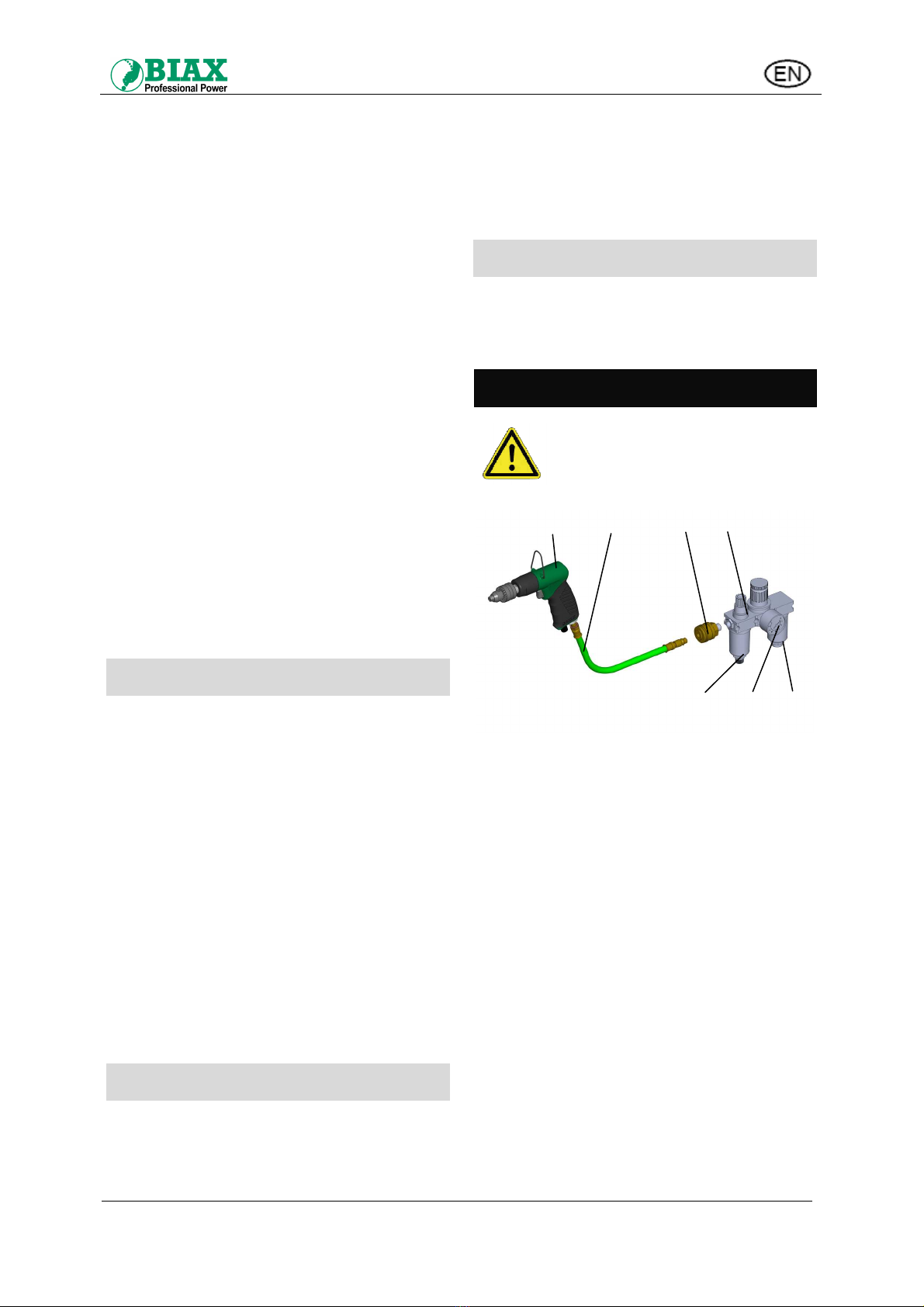
Abb. 7. Connection of compressed air supply
Blow through compressed air hose before connection
to remove impurities!
Mount maintenance unit (pos. D) in the following
order:
Water separator/filter with a filter grade of at least 40
µm (pos. D1) - pressure regulator (pos. D2) - oil mister
(pos. D3).
Set an operating pressure of max. 6 bars at the
maintenance unit. Check oil level and refill oil, if
necessary.
Set the maintenance unit in a way that
2 - 3 drops of oil per minute are added to the air.
Connect the drill (pos. A) with the hose unit (pos. B) to
the maintenance unit using a one-handcoupling (pos.
C).
A B C D
D3 D2 D1
Operating manual for
pneumatic drills
BA-NR.: 001 580 343 10 von 11
Stand 22.04.2014
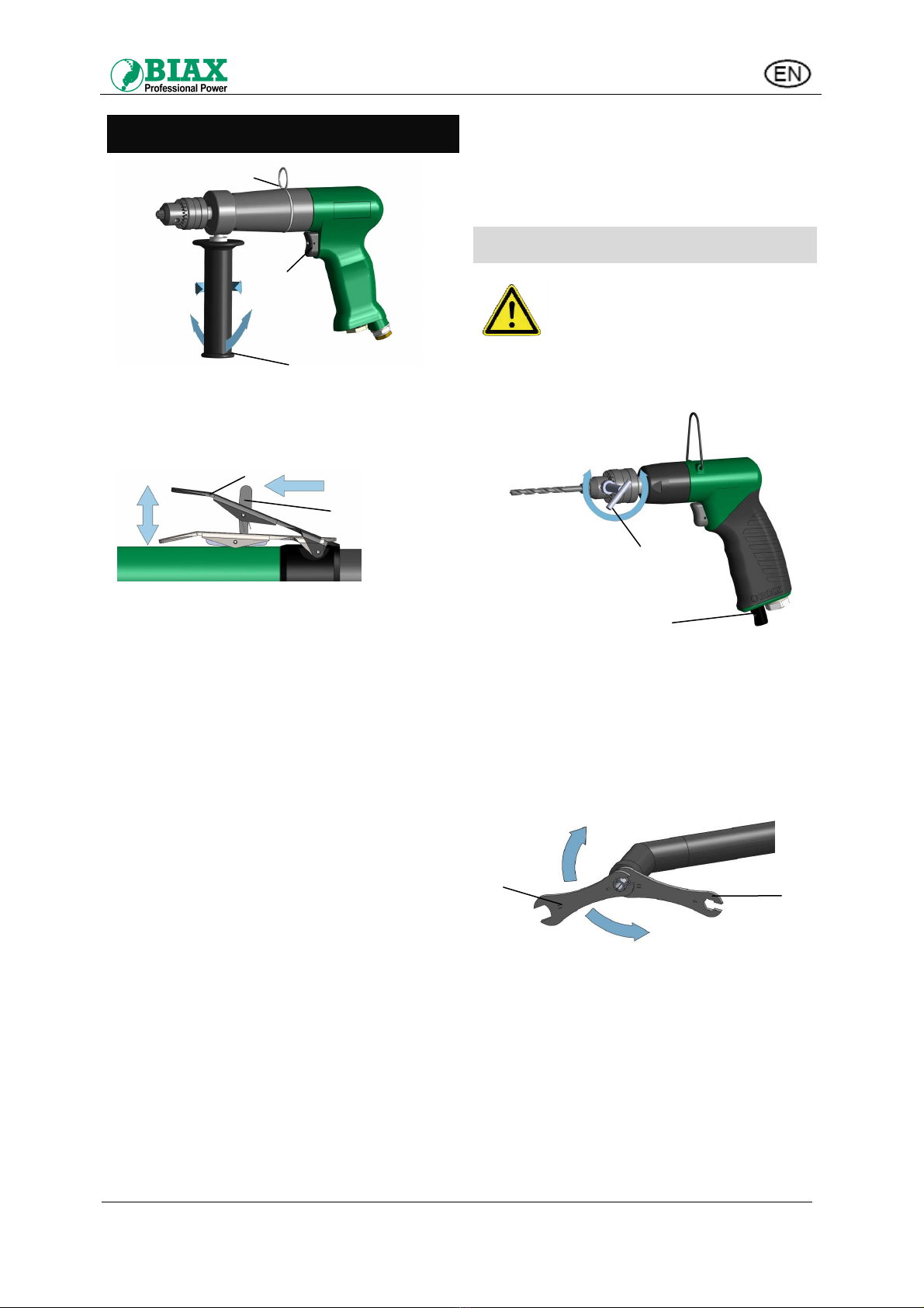
Handling
Abb. 8. Handling the drill
Switching the drill on and off (for type BP)
Press the valve button (pos. F) to switch on the drill.
Release the valve button to switch it off. (See Abb. 8)
Abb. 9. Unlocking and switching/on off the lever valve
Switching the drill on and off (for type
BWH)
To start the machine, push the lever (H) in the
direction of the arrow to unlock the valve lever (I) (see
Abb. 9). Push valve lever (I) in the direction of the
arrow ON. The machine is in operation as long as the
valve lever (I) is pushed down. To switch off release
the valve lever (I). Lever (H) engages, and valve lever
(I) is secured.
Second handle
The drill BP 0,5-10 is fitted with a second handle (pos.
G). Hold the drill with both hands to be able to
counteract suddenly occurring torques.
Adjusting the handle:
Loosen the handle (pos. G) by turning it in the
direction of the „Loosen“ arrow and swivel it into the
desired position. Tighten the handle tightly in the
direction of „Tighten“ arrow.
Suspension bracket (for type BP)
The drill can be mounted on a spring balancer with the
suspension bracket (pos. E). The fastening has to be
secured.
Exhaust air (see Abb. 10)
The machine types BP 500, 800, 1000, 2600, 4500
and 6000 have a turnable exhaust air aperture (pos. J)
at the bottom of the drill.
This allows adjusting the direction of the air outlet
depending on the application.
Putting down the drill
After completing the work put down the drill on a clean
surface.
This prevents that the handle of the drill becomes dirty
or damaged.
Tool change
Caution!
Disconnect the drill from the
compressed air connection every
time before you change a tool!
Type BP 0,5-10, BP 500, BP 800, BP 1000,
BP 2600, BP 4500, BP 6000
Abb. 10. Tool change with key-type drill chuck
•Open the drill chuck with the drill chuck key (pos.
K) which is supplied with the accessories.
•Clamp the tool safely and as deeply as possible
into the drill chuck.
•Then close the drill chuck again with the key.
Type BWH 6-25/2 K45 and BWH 6-25/2 K90
Abb. 11. Tool change with collet
•On drills with a collet the tool change is
carried out with the keys included in the
scope of delivery.
•Hold the spindle with key (L) and open and
close the collet with the second key (M).
Remove any tool key!
Before you switch on the drill ensure that the drill
chuck key and adjustment tools have been removed.
G
F
LoosenTighten
swivel
E
Close
K
Open
J
On
Off
H
L
M
Close
Open
I

Operating manual for
pneumatic drills
BA-NR.: 001 580 343 11 von 11
Stand 22.04.2014
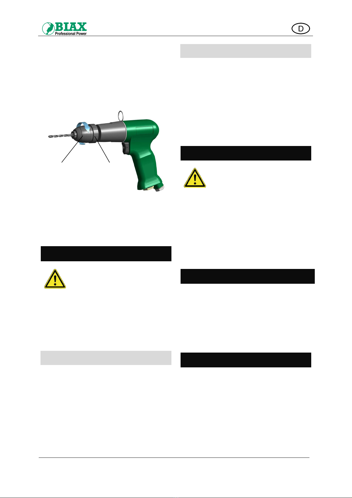
Type BP 3-10
Abb. 12. Tool change with keyless drill chuck
•Hold the ring (pos. O) tightly and open and close
the drill chuck by turning the bushing (pos. N).
•Clamp the tool safely and as deeply as possible
into the drill chuck.
Maintenance
Caution!
Disconnect the drill from the
compressed air connection before
carrying out any maintenance work!
After every 300 operating hours the gear grease has
to be replaced.
Our service department is available to assist you.
Please contact the nearest authorised repair shop or
directly our main office.
Checking the maintenance unit
Before commissioning the drill the following tasks
have to be carried out:
•Removing condensation.
•Refilling special BIAX oil.
•Checking flow pressure
6 bar must not been exceeded.
Maintenance unit
Air supplied via the compressed air system often
contains impurities and is enriched with humidity.
Therefore, a maintenance unit has to be installed
between the compressed air system and the drill.
The maintenance unit regulates the operating
pressure, cleans and dehumidifies the compressed air
and ensures proper lubrication of the pneumatic tool.
This significantly increases usage and life time of the
tools.
You can choose the maintenance unit that is suitable
for your drill and the special oil from our catalogue.
Repair
Attention!
Only authorized staff is permitted to
carry out repairs. Our service
department is available to assist
you.
Only use original parts!
When performance worsens the rotor blades must be
replaced.
Please contact the nearest authorised repair shop or
directly our main office.
Upon request, the corresponding spare part lists can
be handed out to the authorised repair shops. Please
contact our sales department for this purpose.
Disposal
The packaging of the drill mainly consists of recyclable
material. Dispose of it in an environmentally suitable
way.
Do not throw away the drill into normal household
rubbish at the end of its lifetime. Find out option for an
environmentally suitable and professional disposal.
Observe the local and national rules.
Accessories
The scope of delivery includes for the drills with key-
type drill chuck and collet:
Keys for the tool change
Special accessories
Special accessories can you find in our catalogue:
One-handed coupling with hose connection or
external thread, pneumatic armatures, hose units,
hose balancer, workbench equipment, maintenance
units.
Special oil is listed in our catalogue.
N O
Close
Ppen
This manual suits for next models
9
Table of contents
Languages:
Popular Drill manuals by other brands


Parkside
Parkside PABH 20-Li D4 Translation of the original instructions

Silverline
Silverline DIY Series manual

Bosch
Bosch GSR18V-535FC Operating/safety instructions

Panasonic
Panasonic EY7940 operating instructions

Bosch
Bosch GSR 36 V-LI Professional Original instructions

Premier
Premier SA620.V2 instructions