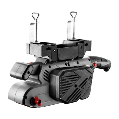
BIAX HB 12 S Operating instructions

001580313 –V12.2021
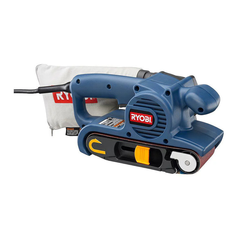
Translation of the operating instructions for the compressed air manual
belt sander
HB 12 S
HBH 200
HB 20
HB 15-1
HB 15-12
HB 3
A copy of this manual must be given to all personnel working with this tool.
Schmid & Wezel GmbH
Maschinenfabrik
Maybachstrasse 2
D - 75433 Maulbronn
Tel.: 07043 1020
Fax: 07043 10278
E-mail: biax-verkauf@biax.de
www.biax.de

Compressed air manual belt sander
Translation of the operating instructions
EN
001580313 –V12.2021 Page 2 of 8
Technical data
Operating pressure
Air consumption
Connection thread
Recommended hose width
Power
Idle speed
Belt speed
Vibration
Sound pressure level
Sound power level
Peak sound pressure level
Weight
bar
l/min
mm
watt
rpm
m/s
m/s²
dB(A)
dB(A)
dB(C)
kg
HB 12 S
150123105
6
550
R1/8”
7
250
20,000
30
< 2.5
K=0.05
LpA = 73
LWA = 84
LpCpeak = 89.9
1.5
KpA = 3
KWA = 3
KpCpeak = 3
HB 15-1
150123645
6
500
R1/8”
7
250
20,000
20
< 2.5
K=0.5
LpA = 75
LWA = 86
LpCpeak = 93.4
1.0
KpA = 3
KWA = 3
KpCpeak = 3
HB 15-12
150123642
6
500
R1/8”
7
300
20,000
20
< 2.5
K=0.5
LpA = 78
LWA = 89
LpCpeak = 98
1.0
KpA = 3
KWA = 3
KpCpeak = 3
HBH 200
150123770
6
550
R1/8”
7
300
20,000
45
< 2.5
K=0.24
LpA = 79
LWA = 90
LpCpeak = 96.3
1.0
KpA = 3
KWA = 3
KpCpeak = 3
HB 20
150122602
6
500
R1/8”
7
230
20,000
45
< 2.5
K=0.16
LpA = 78
LWA = 89
LpCpeak = 98.8
1.5
KpA = 3
KWA = 3
KpCpeak = 3
HB 3
150122200
6
300
R1/8”
5.5
150
28000
30
< 2.5
K=0.24
LpA = 73
LWA = 84
LpCpeak = 89
0.5
KpA = 3
KWA = 3
KpCpeak = 3
Name
Type

Compressed air manual belt sander
Translation of the operating instructions
EN
001580313 –V12.2021 Page 3 of 8
General notes
This operating manual is a component part of the
scope of delivery. It must be kept the vicinity of the
appliance and be handed over with the equipment in
the event of resale.
We reserve the right to make technical modifications
to the unit described in this operating manual within
the scope of product improvements.
Reprinting, translation and copying of this document,
in its entirety or parts of it, require prior written
permission from the publisher.
Copyright is property of the manufacturer.
This operating manual is not subject to a revision
service.
Obligations of the proprietor
The proprietor must observe the applicable national
accident prevention regulations and technical
regulations.
The proprietor must ensure that the appliance is only
operated by trained, responsible personnel.
The proprietor must ensure that operators have read
and understood the operating manual before they
use the appliance.
The proprietor must ensure that unauthorised
persons are denied access to the appliance.
In-house health and safety regulations must be
observed.
Intended use
The BIAX compressed air manual belt sander is used
for
• surface
• form
• and contour sanding
of different materials (metals, wood and glass fibre
reinforced plastics).
Any use of the BIAX compressed air manual belt
sander outside the above-mentioned areas of
application, as well as structural modification of the
sander, is not permitted without the consent of
Schmid & Wezel. In case of violation, any liability for
consequential damage shall be excluded.
Before starting work, ensure that the appropriate
sanding belt is correctly tensioned. Then actuate the
valve and bring the running manual belt sander into
operation.
The BIAX compressed air manual belt sander is only
allowed to be operated with suitable sanding belts
and sanding arms (see catalogue).
The specified speeds and clamping lengths must be
observed.
Observe DIN 69170 and the corresponding
manufacturer's instructions.
Safety
Safety labels
The following key words are used in conjunction with
the safety labels throughout this document to indicate
potential hazards:
Danger!
High risk of fatal or severe injury
and considerable property
damage if the corresponding
safety precautions are not taken.
Warning!
Risk of fatal or severe injury and
considerable property damage if
the corresponding safety
precautions are not taken.
Caution!
Risk of minor injury if the
corresponding safety precautions
are not.
Attention!
Risk of damage to property if the
corresponding safety precautions
are not taken.
Safety instructions
The noise level specified can be
exceeded during some working
processes.
Wear ear protection.
Always wear respiratory protection
when performing work which
produces dust and switch on the
dust extraction system at the work
location.
Sparks or chippings can be
produced during sanding which
could injure the eyes. Always wear
protective goggles while completing
the work.

Compressed air manual belt sander
Translation of the operating instructions
EN
001580313 –V12.2021 Page 4 of 8
Health
Dusts from materials with a lead-content coating, some
types of wood, minerals and metals can represent a
health hazard. Touching or inhaling dusts can be the
cause of allergic reactions and/or respiratory disorders to
the user or persons in the vicinity. Certain dust, such as
that from oak or beech, are considered carcinogenic,
particularly in combination with additives used in treating
wood (chromate wood preservatives). Material
containing asbestos may only be processed by
specialists.
Always wear close-fitting clothes when completing the
work. Remove all jewellery before starting work. Always
wear a hair net if you have long hair.
Avoid contact with power sources. The sander is not
insulated against contact with live parts.
Do not reach into the running belt. Cutting and abrasion
hazard.
Handling the manual belt sander
Before starting work, and after each interruption, check
the machine for damage and wear.
Clean the machine after use, make sure the telescopic
clamping device can still move freely.
Proper functioning of the appliance is only guaranteed if
the oil mist lubricator is checked at regular intervals, the
condensation water is removed and resin and acid-free
oil (special accessory) is topped up.
Complete a 30-second test run before starting to use the
sander.
Always disconnect the machine from the compressed air
supply during belt changes and maintenance work.
The flow pressure of 6 bar must never be exceeded
during operation.
If the air supply is interrupted, switch off the machine
immediately.
In the case of manual belt sanders with a grease nipple
in the angle head, the gear unit should be lightly greased
with special grease after approx. 40 hours of operation
(2 –3 strokes with a grease gun).
The sander runs on after being switched off.
Only set the unit down after it has come to a stop.
Secure the workpiece in a clamping device or a vice.
Note that compressed air stored in the hose can cause
the sander to start unexpectedly.
Only use the sander with an undamaged hose. Check
the components, mains cable and connections for
damage before starting work.
If the sander has fallen down, it must be checked for
possible damage.
Conduct at the workplace
Keep your place of work tidy.
Sparks are generated during sanding. Remove any
combustible objects and materials.
Be aware of the danger of a whipping compressed air
hose.
Always concentrate on the job at hand and keep others
away from the work area.
Keep your tools in a safe, secure place and maintain
them carefully.
Repair work may only be carried out by specialist
personnel.
Use a vacuum cleaner if possible.
Ensure good ventilation at the workplace.
It is recommended to wear a respirator mask complying
with filter grade P2.
Connection and start-up
Connection of the manual belt sander
Warning!
Do not connect the hose unit to
the compressed air supply until it
has been connected to the
machine.
Warning!
Only connect to the pressure
supply when the sanding belt is
tensioned and the valve is
switched off.
Operate the BIAX compressed air manual belt sander
only with clean, water-free air. To do this, connect the
appliance to an oil mist lubricator with a water separator.
The oil mist lubricator should be installed as near as
possible to the sander.
Blow through the pressure hose before connection
to remove impurities.
Mount the oil mist lubricator in the following order:
Water separator –pressure gauge –oil mist unit.
Connect the compressed air manual belt sander (A)
with a hose unit (B) and, if necessary, with a silencer
via a one-hand coupling (C) to the oil mist lubricator
(D). (see Fig. 1)
Set an operating pressure of max. 6.3 bar at the oil
mist lubricator. Check the oil level and top up oil if
necessary.
Adjust the oil mist lubricator to add 2 –3 drops of
oil per minute to the air.

Compressed air manual belt sander
Translation of the operating instructions
EN
001580313 –V12.2021 Page 5 of 8
Fig. 1: Hose connection
Fig. 2: Unlocking lever valve
Handling
Switching On and Off
Unlock the lever valve (F) and push the valve lever (E)
(see Fig. 2).
When the work is finished, release the valve lever (E).
Sanding arm mounting
Warning!
Disconnect the appliance from the
compressed air supply prior to
changing the sanding arm.
Only sanding arms belonging to the respective machine
type are allowed to be mounted.
HB 12 S / HB 15-12
For these types, the sanding arms are available in
2 widths and various shapes.
Please note the following points before mounting:
With the HB 12 S, make sure that the spring is
located between the clamping arm (H) and the
sanding arm. A washer must be located under
the knurled screw (L) (see Fig. 3).
With the HB 15-12, make sure that the spring is
seated in the sanding arm holder. The DUBO
washer must be seated between the sanding
arm and the cap screw (Q) (see Fig. 9).
HBH 200
With this type, the sanding arms are available in 3 widths
and various shapes.
Before mounting, please note the following point:
With the HBH 200, make sure that the spring
and the set screw are seated in the sanding arm
holder sleeve (see Fig. 6).
HB 20
With the HB 20, the sanding arm is firmly connected to
the machine. It is therefore not possible to change the
sanding arm.
HB 3
With this type, the sanding arms are available in 3 widths
and various shapes.
Before mounting, please note the following point:
The guide sleeves (X) must be seated in the
groove.
The guide pin (Z) must be seated in the guide.
The compression spring (Y) must be seated
between the guide sleeve (X) and the sanding
arm (G) (see Fig. 7).
Belt change and sanding arm adjustment
Warning!
Disconnect the appliance from the
compressed air supply prior to
changing the belt.
Warning!
Do not leave any tool keys inserted.
Before starting work, inspect the
cutter to ensure that all spanners
and wrenches have been removed.
Only use type-specific sanding belts with a width that
matches the sanding arm. When inserting the new
sanding belt, pay attention to the running direction
marked with an arrow on the inside of the belt. Incorrect
insertion results in premature wear.
A
B
C
D
OFF
ON
F
E

Compressed air manual belt sander
Translation of the operating instructions
EN
001580313 –V12.2021 Page 6 of 8
Fig. 3: Belt change HB 12 S
Fig. 5: Belt change HB 15-1 / HB 20
Fig. 6: Adjusting the belt run HB 15-1
HB 12 S
Fold the protective cap away to the side. Press the
tensioning arm (H) against the housing and remove the
slackened sanding belt via the sanding arm roller (I) (see
Fig. 4).
During assembly, place the sanding belt around the drive
roller (J) and over the deflection rollers (K). Tighten the
sanding belt with one finger, press the tensioning arm (H)
against the housing, pull the sanding belt over the
sanding arm roller (I) and release the tensioning arm (H).
After changing the sanding belt, close the protective cap
again.
Test run –adjust the belt position during the run by
turning the knurled screw (L).
HBH 200
Slightly loosen nut (T) and screw (S), then push the
sanding arm backwards. Secure again with the screw
(S). After inserting the sanding belt, loosen the screw (S)
slightly so that the sanding belt is tensioned. Lock this
position with the nut (T). With the machine running,
adjust the belt run with screw (U)and lock the setting with
screw (V) (see Fig. 6).
ATTENTION:
If the sanding belt breaks, the deflection roller of the
sanding arm can move in the groove. When the machine
is next put into operation, it must be ensured that the
deflection roller is pressed in as far as the stop in the
sanding arm (see Fig. 10, cut-out stop).
HB 15-1 / HB 20
Press the telescopic sanding arm against the drive roller
(M) from the front and remove the sanding belt by hand
via the drive roller (M) (see Fig. 4).
During assembly, place the sanding belt around the
sanding arm roller (N), press the sanding arm together
and place the sanding belt over the drive roller (M) (see
Fig. 4).
Test run –adjust the belt run using the two cap screws
(P). Depending on the belt run, loosen the corresponding
screw and tighten the second screw (see Fig. 5).
HB 15-12
Loosen the belt tension by turning the knurled screw (Q)
andremovethesandingbeltbyhand.Assemblyinreverse
order. Do not overtension the sanding belt (see Fig. 8).
Test run –adjust the belt position during the run by
turning the cap screw (W).
P
N
O
M
H
K
I
L
J
P
Fig. 4: Belt change HBH 200
Fig. 7: Adjusting the belt run HB 20
Fig. 8: Adjusting the belt run HB 15-12
W
Q
Stop
Sanding arm
Sanding arm holder
Belt running direction

Compressed air manual belt sander
Translation of the operating instructions
EN
001580313 –V12.2021 Page 7 of 8
HB 3
Press the sanding arm (G) back. Press and hold the
locking button (R). Release the sanding arm (G). Now,
after the locking button (R) is released, the sanding arm
should remain in the rear position. Put on the sanding
belt. Briefly press the sanding arm (G) back and release
it. The sanding belt is tensioned.
Test run –adjust the belt position during the run by
turning the knurled screw (Q) (see Fig. 7).
.
Fig. 9: Belt change HB 3
Adjusting the handle (HB 3 only)
The handle with the lever valve can be
turned as required for better handling.
Carefully clamp the belt sander at the angle head in the
vice. Loosen lock nut (3) and turn valve (1) by max. 180°.
Tighten the lock nut again (see Fig. 8).
Fig. 10: Adjusting the handle HB 3
Working with the belt sander
Correctly tension a suitable sanding belt
Actuate valve and bring running machine into
operation
Surface sanding only with belt support
Radii only with roller support
Sanding arm with telescopic clamping, only
with low contact pressure
Maintenance
Oil mist lubricator
To ensure proper functioningof the BIAX compressed air
manual belt sander, the oil mist lubricator should be
checked at regular intervals. Remove any condensation
and top up with BIAX special oil if necessary. This
prevents damage to ball bearings, motor parts and the
rotor caused by dirt or rust particles.
To do this
remove the condensation and
check the operating pressure (max. 6 bar) at
regular intervals.
Checking the idle speed
The idle speed of the sander must be checked every
20 hours of operation. Use a tachometer for this purpose.
At an operating pressure of 6 bar, the nominal speed
must not be exceeded without a sanding tool.
Repair
Warning!
Repairs are only allowed to be
carried out by specialist personnel.
Our Service department is available
to you for this. Only use original
spare parts.
In the case of deteriorating performance, the sander
must be disassembled and cleaned. It is essential to
replace worn rotor blades.
Contact your nearest authorised service centre or our
head office directly.
We can send the appropriate spare parts lists to the
specialist service centres.

Compressed air manual belt sander
Translation of the operating instructions
EN
001580313 –V12.2021 Page 8 of 8
Accessories
The delivery includes the manual belt sander and a key
for adjusting the sanding arm.
Special accessories
Compressed air fittings, one-hand couplings with male
thread or hose connection, filter pressure reducers,
silencers, hose balancers, hose units, collets, spiral
hoses and workbench equipment can be found in our
catalogue.
This manual suits for next models
11
Table of contents
Other BIAX Sander manuals

