BIC V815 User manual

Owner’s Manual
Model V1020
10˝ 160 watt
Powered Subwoofer
Model V1220
12˝ 200 watt
Powered Subwoofer
Designed and engineered in the U.S.A. by
Model V815
8˝ 150 watt
Powered Subwoofer

CAUTION: TO REDUCE THE RISK OF ELECTRIC SHOCK
DO NOT REMOVE COVER (OR BACK)
NO USER-SERVICEABLE PARTS INSIDE
REFER SERVICING TO QUALIFIED PERSONNEL
ATTENTION: POUR EVITER LES RISQUES DE CHOC
ELECTRIQUE, NE PAS ENLEVER LE COUVERCLE. AUCUN
ENTRETIEN DE PIECES INTERIEURES PAR L’USAGER. CONFIER
L’ENTRETIEN AU PERSONNEL QUALIFIE.
AVIS: POUR EVITER LES RISQUES D’INCENDIE OU
D’ELECTROCUTION, N’EXPOSEZ PAS CET ARTICLE
A LA PLUIE OU A L’HUMIDITE
The lightning flash with arrowhead symbol within an equilateral
triangle is intended to alert the user to the presence of uninsulated
“dangerous voltage” within the product’s enclosure, that may be
of sufficient magnitude to constitute a risk of electric shock to persons.
Le symbole éclair avec point de flèche à l’intérieur d’un triangle
équilatéral est utilisé pour alerter l’utilisateur de la presence à
l’intérieur du coffret de “voltage dangereux” non isolé d’ampleur
suffisante pour constituer un risque d’éléctrocution.
The exclamation point within an equilateral triangle is intended to
alert the user of the presence of important operating and maintenance
(servicing) instructions in the literature accompanying the appliance.
Le point d’exclamation à l’intérieur d’un triangle équilatéral est
employé pour alerter les utilisateurs de la présence d’instructions
importantes pour le fonctionnement et l’entretien (service) dans le
livret d’instruction accompagnant l’appareil.
SAFETYINSTRUCTIONS
1. Read Instructions – Read all the safety
and operation instructions before operating the
V815/V1020/V1220.
2. Retain Instructions – Keep the safety
and operating instructions for future reference.
3. Heed Warnings – Follow all warnings on
the V815/V1020/V1220 and in these operating
instructions.
4. Follow Instructions – Follow all operating
and other instructions.
5. Water and Moisture – Do not use the
V815/V1020/V1220 near water – for example,
near a bathtub, washbowl, kitchen sink, laun-
dry tub, in a wet basement or near a swimming
pool.
6. Heat – Locate the V815/V1020/V1220 away
from heat sources such as radiators, or other
devices that produce heat.
7. Power Sources – Connect the
V815/V1020/V1220 only to a power supply of
the type described in these operation instruc-
tions or as marked on the V815/V1020/V1220.
8. Power Cord Protection – Route power
supply cords so that they are not likely to be
walked upon or pinched by items placed
upon or against them, paying particular
attention to cords at plugs, convenience
receptacles, and the point where they exit
the V815/V1020/V1220.
9. Object and Liquid Entry – Do not drop
objects or spill liquids into the inside of the
V815/V1020/V1220.
10. Damage Requiring Service –
V815/V1020/V1220 should be serviced
only by qualified service personnel when:
A. V815/V1020/V1220 power-supply
cord or the plug has been damaged; or
B. Objects have fallen, or liquid has
spilled into the V815/V1020/V1220; or
C. V815/V1020/V1220 has been exposed
to rain; or
D. V815/V1020/V1220 does not appear to
operate or exhibits a marked change in
performance; or
E. The V815/V1020/V1220 has been
dropped, or its chassis damaged.
11. Servicing – Do not attempt to service
the V815/V1020/V1220 beyond those
means described in this operating manual.
All other servicing should be referred to
the qualified service personnel.
12. To prevent electric shock, do not
use the V815/V1020/V1220 polarized
plug with an extension cord, recep-
tacle or other outlet unless the
blades can be fully inserted to pre-
vent blade exposure.
Pour préevenir les chocs électriques ne
pas utiliser cette fiche polariseé avec un
prolongateur, un prise de courant ou une
autre sortie de courant, sauf si les lames
peuvent être insérées à fond sans laisser
aucune pariie à découvert.
13. Grounding or Polarization – Do not
defeat the grounding or polarization of the
V815/V1020/V1220.
14. Internal/External Voltage Selectors –
Internal or external line voltage selector
switches, if any, should only be reset and re-
equipped with a proper plug for alternate
voltage by a qualified service technician.
This apparatus does not exceed the Class
A/Class B (whichever is applicable) limits
for radio noise emissions from digital
apparatus as set out in radio interference
regulations of the Canadian Department
of Communications.
ATTENTION – Le présent appareil numér-
ique n’émet pas de bruits radioélec-
triques dépassant las limites applicables
aux appareils numériques de class A/de
class B (selon le cas) prescrites dans le
règlement sur le brouillage radioélec-
trique édicté par les ministere des com-
munications du Canada.
WARNING — To reduce the risk of fire
or electric shock, do not expose this
component to rain or moisture.
TABLEOF
CONTENTS
A.UNPACKING . . . . . . . . . . . 3
B.V815/V1020/V1220
AMPLIFIER PANEL TOUR 3
C.PLACEMENT . . . . . . . . . . . 4
D.HOOKUP . . . . . . . . . . . . . . 5
E.INITIAL LISTENING TESTS
& ADJUSTMENTS . . . . . . . 9
F. SPECIFICATIONS . . . . . . 10
G.TROUBLESHOOTING AND
SERVICE . . . . . . . . . . . . . 10
H.WARRANTY . . . . . . . . . . 11
2

UNPACKING
Remove the V815/V1020/V1220 from its
packing carefully and inspect it for any
shipping damage. If you discover damage,
contact your B.I.Cdealer immediately.
If possible, save the carton and internal
packing. It’s the best possible protection
for your V815/V1020/V1220 if you need
to move it or return it for service.
Keep your sales receipt in a secure
place. It helps establish the duration of
your warranty and is good for insurance
purposes (just in case anything happens
to your stereo system).
3
A
B
Congratulations on your purchase ofa
B.I.CAmerica V815/V1020/V1220 powered
subwoofer. It will give your stereo system
unparalleled low frequency output.
Bass frequencies are critical to realistic
sound reproduction. After you’ve hooked up
your V815/V1020/V1220 subwoofer, you’ll
discover just how much “punch” and depth
you’ve been missing. No matter what kind of
music or videos you listen to...whether you
listen to it loud or soft, you’ll experience
sound that’s richer and fuller. Bass guitar
and string bass will have more impact.
You’ll be able to FEEL as well as hear per-
cussion – just the way you would at a live
performance. If you have an audio/video
system, movies will come alive with thun-
derous sound effects that were never pos-
sible without the V815/V1020/V1220.
The V815/V1020/V1220 is a self-powered
V815, V1020,
ANDV1220
AMPLIFIER
PANELTOUR
Before actual hookup, you should famil-
arize yourself with the connections on the
back of the V815/V1020/V1220, as shown
in Drawing 1 below.
1. FROMRECEIVER. Connects to your
receiver’s speaker terminals. These bind-
ing post, color-coded connectors are used
to hook the V815/V1020/V1220 to your
receiver if it does not have sub- woofer out
or LFEoutput connections. This is
explained in section 9.
2. OUTTOSPEAKERS. If you are using the
V815/V1020/V1220 from receiver inputs,
you will hook your main speakers to these
binding post, color-coded connections.
They are NOT used if you are using the LFE
(SUB) IN line level connection.
subwoofer that frees your receiver or
power amplifier from the power demands
of reproducing very low frequencies. To do
this, the V815/V1020/V1220 incorporates
its own built-in crossover system that auto-
matically “assigns” higher frequencies to
your main speakers and lower freqoencies
to its own power amplifier, contained with-
in the subwoofer enclosure.
The V815/V1020/V1220 has been metic-
ulously designed and tested to insure high-
performance, durability and longevity.
This manual is designed to take you step-
by-step through the hook-up and operating
process. This procedure is not difficult, but
itIS slightly different than hooking up a line
level component such as a cassette deck or
CD player. Reading this manual carefully
will insure that you get maximum perfor-
mance from your V815/V1020/V1220.
1
2
3
45
6
7
8
9
10
11
DRAWING 1 - V815/V1020/V1220 rear panel

4
C
PLACEMENT
Where to position your
V815/V1020/V1220
The V815/V1020/V1220 operates at low
bass frequencies which are essentially
omni-directional. That means you can
place the V815/V1020/V1220 almost any-
where in a room without compromising the
effectiveness of your main stereo speakers.
Four factors need to be considered:
1)distance from your main speakers;
2)distance from a wall outlet;
3)distance from your receiver; and
4)proximity to walls and corners.
3. REMOVABLEFUSEHOLDER. By push-
ing in and turning counter-clockwise,
you can remove and replace the fuse.
Check the rating on the fuse for proper
size of your unit.
4. POWER INDICATOR. When the amp-
lifier is ON, this indicator will be green.
When the amplifier is in the STANDBY
mode, as mentioned in item 5, this indi-
cator will be red.
5. POWER/AUTO ONSWITCH. This tog-
gle switch turns the V815, V1020, or
V1220 on and off. When the switch is in
the ON position, the amplifier will stay
on as long as the switchremains in that
position. When this switch is in the
AUTO position, the amplifier will stay
turned on as long as a signal is being fed
to the subwoofer amplifier. 15 to 20
minutes after you stop playing music or
a video, the amplifier goes into STAND-
BY mode – see (4). When you again
begin to play music or a video, the
amplifier will automatically turn on.
6. PHASE SWITCH. This switch is used
to set the subwoofer’s phase to either
normal “0º” or reverse “180°” (out of)
phase. Once you determine the place-
ment of the V815/V1020/V1220, you will
need to try both positions of this switch
for the best bass output for your listen-
ing position. The physical location of
your subwoofer and main speakers
determines the phase setting that will
sound best at your main listening posi-
tion. If this requires using the “180°”
mode, don’t worry, there is nothing
“abnormal” about it.
7. VOLUMECONTROL. Rotating this
knob clockwise increases the output
level of the subwoofer. To start out,
make sure that the VOLUME is turned all
the way down (fully counterclockwise).
Later, after some initial listening tests,
you can adjust the volume to your own
tastes. However, care should be taken
not to overdrive the subwoofer to the
point of audible distortion.
8. CROSSOVER FREQUENCY CONTROL.
This control determines what lower part
of the frequency spectrum will be repro-
duced by the V815, V1020, or V1220and
what higher parts will be handled by
your main speaker. It is a “crossover”
control. Rotating the knob sets the point
where all lower frequencies will be han-
dled by the subwoofer and all higher fre-
quencies will be routed to your main
stereo speakers.
As a starting point, set the control
around 80 Hz. if you are using left and
right tower speakers, 100 Hz. with
bookshelf speakers, and 120 Hz. with
small mini-speakers.
Note:If you use the SUB IN connector,
the RECEIVER TYPE toggle switch must
be in the Pro Logic mode for the
crossover frequency control to operate.
9. SUB IN. This connection is used
ONLY if you have a Dolby Pro Logic or
Dolby Digital receiver/integrated amplifi-
er which has a subwoofer output.
10. RECEIVER TYPE TOGGLE SWITCH.
If you use the SUB IN connector (item
9), you must set this switch to the type of
receiver you have.
Note:When this switch is set to DIGITAL
RECEIVER5.1, 6.1, 7.1, the CROSSOVER
FREQUENCYcontrol (9) does not affect
the signal.
11. POWER INPUT. This connector
is the AC power in. Your subwoofer is
supplied with a removable power cord
that mates to this plug.
1.Distance from your main speakers.
The best placement for your subwoofer is
on the same wall as the main speakers,
especially if you are matching up with
small bookshelf speakers. With tower
speakers, side wall or rear placement is
also acceptable.
2.Wall outlet.Since the V815, V1020,
and V1220 require AC power, it must be
placed within ten feet of a wall outlet. We
don’t recommend extending that range
with an extension cord.
3. Connections to your receiver,
integrated amplifier or preamplifier.
If your receiver or integrated amplifier
does not have a subwoofer output or LFE
output (see next page), hookup between
the amp and V815/V1020/V1220 will be
made with speaker wire. You can basically
place the V815/V1020/V1220 anywhere in
a normal-sized room.
4. Proximity to walls and corners.
Physical placement of the subwoofer will
have a definite impact on the frequency
response and the perceived amount of
V815/V1020/V1220 bass output. Because
low frequencies have long wavelengths,
they are influenced by proximity to a
boundary such as a wall or floor.
See Drawing 2 on the facing page. When
you place the V815/V1020/V1220 well
away from a wall, it will produce bass at a
certain level. Move the subwoofer close to

5
D
Away from walls:
Normal bass Against walls:
More bass In Corner:
Most bass
Away from walls:
Normal bass Against walls:
More bass In Corner:
Most bass
DRAWING 2 - V815/V1020/V1220 placement
the wall, it will produce more output
(about 3dB more). Putting the subwoofer
in a corner will increase output another
3dB (6dB more than when placed away
from walls and corners).
All this technical jargon may sound con-
fusing, but it basically means that you have a
number of options, each of which produces
a different amount of bass. For example, if
you like a lot of heavy bass, consider putting
the V815/V1020/V1220 into a corner. If you
like smoother, less-obvious bass, move the
subwoofer out into the room. The main
thing to remember is that there is no
“right” or “wrong” place to put the
V815/V1020/V1220(assuming it’s less than
ten feet from a wall receptacle). It all
depends on how much bass you want.
Another reason to experiment – because
low bass waves are very large (up to forty
feet or more across!), they tend to cancel
and reinforce each other, causing places in
the room where there is lots of bass and
others where there isn’t very much at all. If
you walk around your listening room while
playing music, you’ll probably discover
Connecting the
V815/V1020/V1220
to a wall plug
The V815/V1020/V1220 draws a moder-
ately high amount of current. We do not
recommend plugging it into a “conve-
nience” outlet (switched or unswitched)
that is often found on the back of receivers
and other stereo components.
Instead, connect the V815, V1020, or
V1220ONLY to its own AC outlet. See items
8 and 9 in the Safety Instructions at the
beginning of this manual.
HOOKUP
Two basic
connection options
1. Amplifier/speaker hookup
If you own a receiver or integrated ampli-
fier that does NOT have a subwoofer out-
put or LFE output, use Method A - Amplifier
Wiring Hookup as shown in Drawing 3
(page 7). To determine whether your re-
ceiver has a subwoofer output,look on the
back for an RCA-type connector labelled
subwoofer out or LFE out.
If your receiver or integrated amplifier
doesn’thave a subwoofer or LFE output,
use Method A - Amplifier Wiring Hookup
Steps for Most Receivers (Drawing 3).
2. Line level hookup
If you own a receiver or integrated amp-
lifier with a subwoofer or LFE output, you
would use Method B - Line Level Hookup
as shown in Drawing 4.
these sorts of areas where bass is either
exaggerated or reduced. Needless to say, if
your main listening area ends up in a
“dead” space, you will need to move the
V815/V1020/V1220 so that bass is more
normal.
Incidentally, moving the V815, V1020, or
V1220 around won’t affect the stereo
imaging of your main stereo system, so feel
free to try various subwoofer positions.

6
Speaker wire tips
If you are using Method A as shown in
Drawing 3, here are some suggestions
that will insure proper operation:
Speaker wire type
The choice of speaker wire is depen-
dent on the type of amplifier, the dis-
tance you intend to run the wire, and
your budget. In general, you should not
use extremely thin wire. If in doubt as to
what brand or type of wire to use, con-
sult your audio dealer.
Length of speaker wires
When hooking up your main/satellite
speakers, make the hookup wires the
SAME LENGTH for BOTH speakers, even
if one speaker is much closer to your
amplifier than the other. You may need
to loosely coil up part of one channel’s
wire behind the amplifier if one speaker
is quite close and the other far away
from the amp or receiver. But it’s worth
it. Keeping both wires the same length
will help maintain proper signal balance
and imaging. Likewise, when making
connections between your receiver and
the V815/V1020/V1220’sFROMRECEIV-
ER terminals, make sure that the wire
lengths are the same.
Establishing polarity
It is very important that left and right
connections be made with the same
plus/minus polarity.
•Most speaker wire is polarity coded.
This means that each conductor is labeled
either “+” positive or “–” negative. The
(+) positive conductor may be a differ-
ent color or texture than the (–) negative
conductor. For example, it may be cop-
per-colored (instead of silver-colored),
have a white stripe printed on it, have a
series of fine ridges stamped in it or sim-
ply be labeled with little “+” marks.
•V815/V1020/V1220 FROM RECEIVER
terminals and OUT TO SPEAKERS termi-
nals are color-coded: Red for positive
(+) and black for negative (–).
•Any connection that uses speaker wire
requires care in maintaining polarity.
When connecting speakers or a sub-
woofer to speaker terminals, or during
V815/V1020/V1220
Method A Hookup,
make sure to connect “+” wires to “+”
terminals, and “–” wires to “–” termi-
nals. For example, if your speaker wire
has one copper-colored conductor and
one silver-colored conductor, connect
both ends of the copper-colored wire
(+)to red (+) terminals. Likewise, con-
nect the wire you’ve identified as negative
(in this case, the silver-colored wire), to
black (–) terminals.
Method A:
Amplifier wiring
hookup steps for
receivers or surround
sound receivers with
NO sub output jack
Refer to Drawing 3 on page 7
o1. IMPORTANT: Make sure that ALL
stereo system components including
the V815/V1020/V1220 are turned
OFF before proceeding.
o2. Following the prior instructions on
this page, strip and twist TWO lengths of
speaker wire that will reach between your
receiver’s left and right speakers terminals
and the V815/V1020/V1220. Make these
two lengths of wire only as long as is neces-
sary to run between the two components.
o3. Connect one speaker wire to the
RIGHT “+” and “–” speaker terminals of
your receiver or integrated amplifier. Then
connect the other end of this speaker wire
to the RIGHT“+” and “–” FROM RECEIV-
ERterminals on the back of the
V815/V1020/V1220. Use the tips on deter-
mining speaker wire polarity to make sure
that “+” is connected to “+” and “–” is
connected to “–”.
o4. Connect the other speaker wire to
the LEFT “+” and “–” speaker terminals of
your receiver or integrated amplifier. Then
connect the other end of this speakerwire
to the LEFT “+” and “–” FROM RECEIVER
terminals on the back of the
V815/V1020/V1220. As in step 3, double
check “+” and “–” polarity.
o5. Connect your main/satellite speakers
to the V815/V1020/V1220 OUT TOSPEAK-
ERSterminals.
o6. You are now ready to put your
V815/V1020/V1220 subwoofer into use.
Skip to “E – INITIAL LISTENING TEST.”
Preparing speaker wire
1.Separate the two
conductors that make
up each wire for a dis-
tance of about one inch.
Then strip off 1/2˝of insula-
tion from both ends of each
conductor using a wire strip-
per, diagonal pliers or knife.
2. Twist each set of thin wires
into a tightly bunched spiral.
If your wire is exceptionally thick (12-
gauge zipcord or special speaker inter-
connect cable), divde the strands into
three equal bundles and twist each into a
spiral.
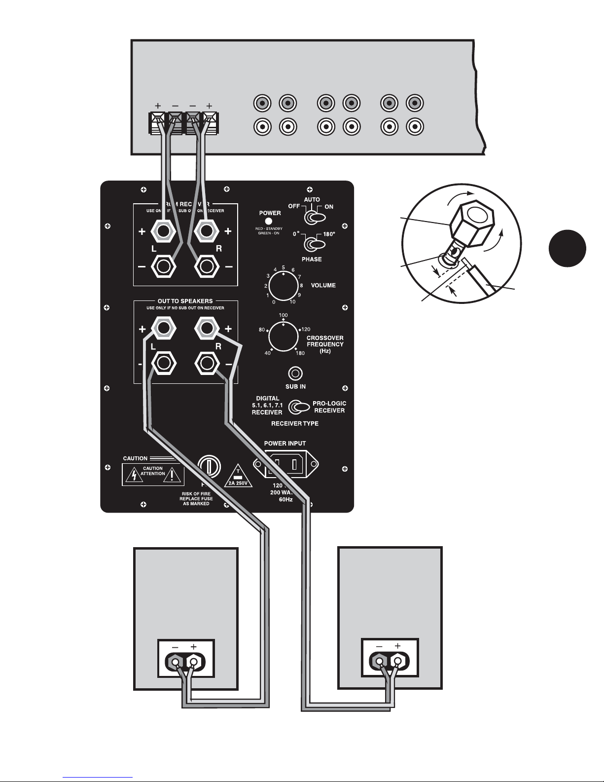
7
DRAWING 3 - Hookup for Receivers and
Integrated Amplifiers without a Subwoofer Output
RECEIVERORINTEGRATED AMPLIFIER
FRONT
SPEAKERS
LEFT RIGHT
COLOR
TOP
SHAFT
STRIPPED
END (1/2˝) WIRE
To connect wire:
1. Unscrew (counter- clockwise)
the top (color portion)
2. Place the stripped metal wire
in the hole in the metal shaft
3. Tighten (clockwise) the top
(color portion) back down on
wire (make sure wire insulation
is not under the plastic nut).
FRONTLEFT
SPEAKER FRONTRIGHT
SPEAKER
V815/V1020/V1220
SPEAKERWIRE
CONNECTIONDETAIL
loosen
tighten
1/2˝
8
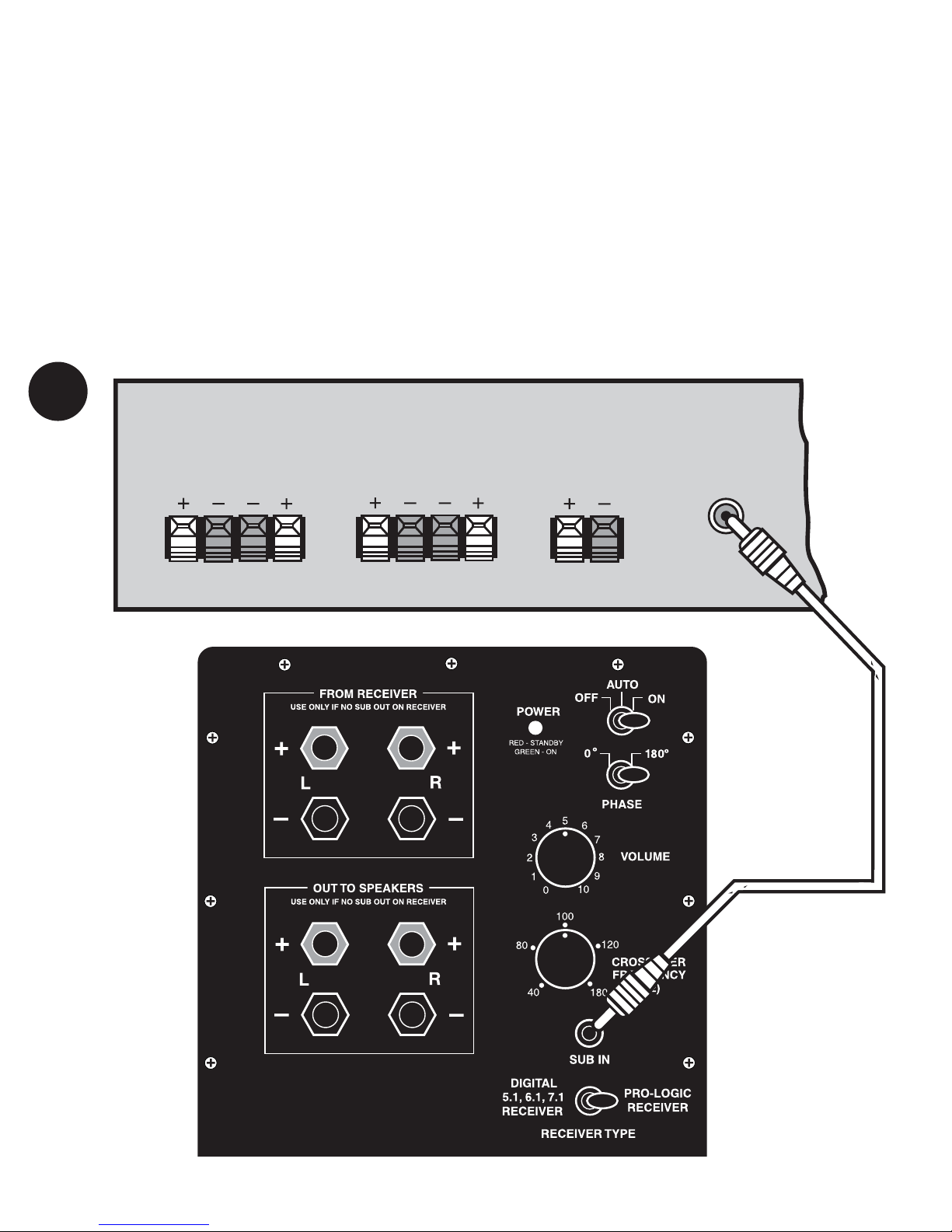
Method B: Line level
hookup steps for
receivers with
subwoofer connections
See Drawing 4 below
Note:This connection method is only for
receivers that have a subwoofer or LFE
output. If your receiver does not have a
subwoofer or LFE connection as shown in
Drawing 4, use Method A – Amplifier
Wiring Hookup Steps for Most Receivers
on page 6. You will need one line level RCA
toRCA connector cable long enough to
reach from your receiver to your
V815/V1020/V1220 location. This should
be available from your B.I.C America deal-
er or from radio supply stores.
o1. IMPORTANT:Make sure that ALL
stereo system components including
the V815/V1020/V1220 are turned
OFF before proceeding.
o2. Locate the subwoofer or LFE output
connectoron the rear of your receiver and
connect one end of the RCA line level cord
to it.
o3. Route the line cord to the subwoofer
location (trying to minimize areas where it
may be stepped on) and connect the other
end directly to the SUB IN.
o4. Connect your main (and surround
speakers if applicable) to the receiver
according to the receiver’s owner’s manual.
o5. Set the RECEIVER TYPE toggle switch
to the type of receiver you have. Note: If
you are using a Dolby Digital type receiver,
the subwoofer crossover control does not
work. You must set the crossover frequen-
cy in your receiver (check your receiver’s
owner’s manual).
o6. You are now ready to put your
V815/V1020/V1220 subwoofer into use.
Skip to the next section, titled E –Initial
Listening Test.
DRAWING 4 - Hookup for Surround Sound Receiver with Subwoofer Output
FRONT
SPEAKERS
RIGHT LEFT
REAR
SPEAKERS
RIGHT LEFT
CENTER
SPEAKERS
RIGHT LEFT
SUBWOOFER
ORLFE
OUT
SURROUNDSOUNDRECEIVER
NOTE:
SEE ITEM 5 ABOVE FOR
PROPER RECEIVER
TYPE SWITCH SETTING

INITIAL
LISTENING TEST
It’s now time to introduce the V815, V1020,
and V1220 amplifier’s potent and plentiful
bass into your listening environment.
o1. Double-check all connections.
o2. Make sure that the volume controls
on both the V815/V1020/V1220 and your
receiver/integrated amp/preamp are turned
all the way down (fully counterclockwise).
Set the PHASE switch to normal. Set the
CROSSOVER FREQUENCY knob to 80 Hz.
Set the SUBIN switch to the type of receiver
you have.
o3. Turn on your stereo system. THEN
turn on the V815/V1020/V1220. Confirm
that the V815/V1020/V1220’sgreen POWER
indicator is glowing. If it isn’t, check the
power connections between the
V815/V1020/V1220 and the wall socket.
o4. Play a musical selection that you are
familiar with. Pick a song that has regular
low bass beats. Advance the receiver/inte-
grated amp/preamp’s volume control up to
a normal listening level. If you don’t hear
sound through your main speakers, turn off
the system and check connections. Also
consult the troubleshooting tips on page 10.
o5. If sound is indeed coming out of your
main speakers, turn the V815/V1020/V1220’s
VOLUME control clockwise until you hear
noticeable additional bass. If you don’t hear
bass by the time you have advanced the sub-
woofer’s VOLUME control halfway, turn off
the system and check connections. Also
consult the troubleshooting tips on page
10.
o6. Adjust the V815/V1020/V1220’s VOL-
UME control until you are satisfied with the
amount of bass. You may want to try sever-
al different albums, tapes or compact discs
while determining how high to adjust the
V815/V1020/V1220’s VOLUME. The amount
of bass varies from album to album and
between different types of music.
E
9
Caring for Your
V815/V1020/V1220
The V815/V1020/V1220 enclosure is
finished in a very high quality polymer
laminate covering that is both attractive
and excellent protection for the wood
cabinet. To remove fingerprints, splatters
of diet soda, peanut butter or other real-
world substances that mysteriously seem
to appear on stereo components, use a
damp, soft cloth on the laminate. You
may also use a high-quality furniture pol-
ish to maintain the original luster.
o7. Now that you have adjusted the
quantity of bass via the volume, it’s time
to work on the qualityof the bass with the
CROSSOVER FREQUENCYcontrol, PHASE
switch – and experimentation with
V815/V1020/V1220 room position.
• While playing music, move the subwoof-
er around, in and out of corners, closer
and farther from the wall, etc. as much as
the power cord and other connections will
allow.
• Change the PHASE switch back and forth
from 0º to 180º while someone sits in the
main listening position. Leave the switch in
the position where you like the bass most.
• Change the CROSSOVER FREQUENCY
control (for Dolby Pro-Logic receivers) to
higher and lower settings. If the
CROSSOVER FREQUENCY control is set too
high, you’ll start to hear low midrange
(voices and instruments) through it. This
will negatively affect the stereo imaging of
your main speakers. Back the CROSSOVER
FREQUENCY setting off until you hear only
bass from the V815/V1020/V1220. If the
CROSSOVER FREQUENCY control is set too
low, you simply won’t get much output
from the subwoofer. Move it back closer to
80Hz.
o8. After you are satisfied with the output
of your V815/V1020/V1220, you can make
all your volume settings through your main
stereo system’s volume control. The only
time you might want to re-adjust the
V815/V1020/V1220’sx VOLUME is when
you encounter a musical selection that has
abnormally low – or high – bass.
You can leave the V815/V1020/V1220
turned on and in AUTO mode when not in
use. It does not draw much power in this
state and will be ready to add low bass the
moment you begin to play music.
Remember, you don’t have to do anything
except leave the POWER switch in the
AUTOposition. The V815/V1020/V1220
will automatically go into STANDBY mode
after 10 to 20 minutes, when no music is
playing.
If you’re not using your stereo system for
a long period of time (such as when you’re
onvacation), turn the POWER switch to the
OFF position.

F
10
TROUBLE-
SHOOTING AND
SERVICE
Before returning your V815, V1020, or
V1220 for service, you can save time (and
often embarrassment) by checking for a few
problems that are most often encountered.
Power light is not lit. No
sound.
1.Is your V815/V1020/V1220 plugged in
to a live AC wall socket?
2.Is the power cord firmly plugged into the
sub amp power input connector? (11) on
page 3.
3.Is the power switch on?
4. Has the V815/V1020/V1220 overheated
and shut off temporarily?
5.Is the fuse OK?
No sound from either set of
speakers.
1.Are your other components turned on?
2. Is the receiver or preamp set to the
appropriate input and is that sound source
playing?
3.Do you have an unconnected tape moni-
tor selected?
4.Is the V815/V1020/V1220 correctly con-
nected to your receiver, preamplifier or inte-
grated amplifier and turned on?
Sound comes from main
speakers but not subwoofer
1. Is the V815/V1020/V1220 turned on
(power light in the green mode) and VOL-
UMEcontrol turned up?
2.Check the speaker connections for small
strands of wire touching both terminals.
3. Some digital receivers only send a sub
out signal when in the movie or digital mode.
In the 2 channel (stereo music) mode, no
sub out signal is sent to the sub.
You may need to set your main speakers to
“small” mode in your receiver setup to get
the receiver’s subwoofer output to turn on.
Check your receiver’s owner’s manual for
subwoofer operation.
G
SPECIFICATIONS
V815/V1020/V1220
Design
Venturi ported system
Amplifier Power
V815 - 150 watts RMS (325 max.)
V1020 - 160 watts RMS(350 max.)
V1220 - 200 watts RMS(430 max.)
Signal-to-Noise Ratio
Greater than 80 dB
Damping factor >500
Crossover
40-180 Hz. (user variable),
active low-pass, 24 dB/octave
Subsonic Filter
18 dB/octave below 20 Hz.
Line Level Sensitivity
8mV
Speaker Level Sensitivity
100 mV
Line Level Input Impedance
10,000 ohms (10K)
Speaker Level Input Impedance
1,000 ohms (1K)
Driver Complement
V815 - One 8˝ long-throw woofer
V1020 - One 10˝long-throw woofer
V1220 - One 12˝long-throw woofer
Frequency Response
V815 - 27-180 Hz. variable
V1020 - 26-180 Hz. variable
V1220 - 23-180 Hz. variable
Dimensions
V815 - 17˝ H x 13˝ W x 10˝ D
V1020 - 16.5˝ H x 15˝ W x 13˝ D
V1220 - 18.5˝ H x 17˝ W x 14˝ D
Shipping Weight
V815 - 27 lbs.
V1020 - 34 lbs.
V1020 - 41 lbs.
Available Finishes
Black laminate
4. For digital receivers – make sure the
subwoofer is “ON” and the subwoofer level
is set to “0dB” or greater.
Sound comes from the
subwoofer but not your
main speakers
1. If you have used either version of
Hookup Method A, check the connections
between the OUT TO SPEAKERS on the back
of the V815/V1020/V1220 and your main or
satellite speakers.
2. If you have used Hookup Method B
(Line Level)...
• confirm that the power amplifier is turned
on.
• check the RCA patch cord
• check the speaker wire connections be-
tween the power amplifier and main or
satellite speakers.
Bass is muffled or weak
1. Check speaker wire polarity of all
connections.
2. Reposition your subwoofer. At some
points in the room, its output may be
cancelled by the geometry of the room.
Moving the V815/V1020/V1220 can
eliminate this problem.
Please refer to Item 10 in the Safety
Instructions for conditions that ALWAYS
require service by qualified personnel.
If you have tried all the above and still
cannot get the V815/V1020/V1220 to op-
erate properly, consult your dealer or call
Tech Support at 1-877-558-4242(4BIC).

WARRANTY
INFORMATION
We suggest that you read the LIMITED
WARRANTY completely to fully understand
your warranty/service coverage. Be sure to
save the sales receipt in a safe place. It will
be necessary for warranty service.
If
your V815/V1020/V1220 should require
service, we suggest that you contact the deal-
er from whom you purchased it.
If the dealer is unable to take care of
your needs, you may contact us at the
phone number shown at the bottom of this
page. We will then direct you to the nearest
in our national network of Authorized
Warranty Service Centers, or give you
detailed instructions on how to pack and
return the product to us for prompt action.
V815/V1020/V1220
Powered Subwoofer
Limited Warranty
If the
B.I.CSpeaker system proves to be
defective in materials or workmanship
within seven years (two years for the elec-
tronic amplifier) from the date of the orig-
inal customer’s purchase, we will, at our
option, repair or replace the defective
product. If for any reason, we are unable
to repair or replace a defective product
within a reasonable time, we will refund
your purchase price.
*DISCLAIMER
THE WARRANTY STATED HEREIN IS IN LIEU
OF ALL OTHER WARRANTIES, EXPRESS OR
IMPLIED, INCLUDING MERCHANTABILITY AND
FITNESS FOR PARTICULAR PURPOSE AND ALL
OTHER LIABILITIES AND OBLIGATIONS OF
B.I.C AMERICA, ALL OF WHICH ARE EXPRESSLY
DISCLAIMED. B.I.C AMERICA HAS NOT MADE
AND DOES NOT HEREBY MAKE ANY OTHER
REPRESENTATION, WARRANTY OR COVENANT
WITH RESPECT TO THE CONDITION, QUALITY,
DURABILITY, DESIGN, OPERATION, CAPACITY,
FITNESS FOR USE OR SUITABILITY OF THE
B.I.CELECTRONICPRODUCT.
Exclusion of
Certain Damages
B.I.C America’s liability for any defective
product is limited to repair or replacement
of the product at our option. B.I.CAmerica
shall not be liable for incidental or conse-
quential damages of any kind or character
because of product defects. Some states
do not allow limitations on how long an
implied warranty lasts and/or do not allow
the exclusion or limitation of incidental or
consequential damages, so the above limi-
tations and exclusions may not apply.
H
11
This Warranty Does
Not Cover:
Damage caused by abuse, accident,
misuse, negligence, or improper operation.
Products that have been altered or
modified.
Any product whose serial number has
been altered, defaced, or removed.
Normal wear and maintenance.
Damages caused by shipping. (All
claims for shipping damage must be
made with the carrier.)
Warranty Service
Warranty service must be performed by an
authorized service center, usually a B.I.C
America dealer or its authorized agent.
You may obtain a list of authorized service
centers by calling the number below.
All warranty repairs must be accompan-
ied by the original bill of sale. No other
document is acceptable or is required.
This warranty gives you specific legal
rights, and you may also have other rights
which vary from state to state.
Due to our continual efforts to improve product
quality as new technology and techniques become
available, B.I.CAmerica reserves the right to revise
its Speaker Systems specifications without notice.
©2012 B.I.C America
B.I.CAmerica
925 N. Shepard Street
Anaheim, CA 92806
www.bicamerica.com
Contact your dealer for warranty
repair or technical help, or
call
1-877-558-4242 (4BIC) for Tech Support.
This manual suits for next models
2
Table of contents
Other BIC Subwoofer manuals


