BIC Venturi V-80 User manual
Owner’s Manual
Model
V-80
8˝ 100 watt
Powered
Subwoofer
CAUTION: TO REDUCE THE RISK OF ELECTRIC SHOCK
DO NOT REMOVE COVER (OR BACK)
NO USER-SERVICEABLE PARTS INSIDE
REFER SERVICING TO QUALIFIED PERSONNEL
ATTENTION: POUR EVITER LES RISQUES DE CHOC
ELECTRIQUE, NE PAS ENLEVER LE COUVERCLE. AUCUN
ENTRETIEN DE PIECES INTERIEURES PAR L’USAGER. CONFIER
L’ENTRETIEN AU PERSONNEL QUALIFIE.
AVIS: POUR EVITER LES RISQUES D’INCENDIE OU
D’ELECTROCUTION, N’EXPOSEZ PAS CET ARTICLE
A LA PLUIE OU A L’HUMIDITE
The lightning flash with arrowhead symbol within an equilateral
triangle is intended to alert the user to the presence of uninsulated
“dangerous voltage” within the product’s enclosure, that may be
of sufficient magnitude to constitute a risk of electric shock to persons.
Le symbole éclair avec point de flèche à l’intérieur d’un triangle
équilatéral est utilisé pour alerter l’utilisateur de la presence à
l’intérieur du coffret de “voltage dangereux” non isolé d’ampleur
suffisante pour constituer un risque d’éléctrocution.
The exclamation point within an equilateral triangle is intended to
alert the user of the presence of important operating and maintenance
(servicing) instructions in the literature accompanying the appliance.
Le point d’exclamation à l’intérieur d’un triangle équilatéral est
employé pour alerter les utilisateurs de la présence d’instructions
importantes pour le fonctionnement et l’entretien (service) dans le livret
d’instruction accompagnant l’appareil.
SAFETY INSTRUCTIONS
1. Read Instructions – Read all the safety
and operation instructions before operating
the V-80.
2. Retain Instructions – Keep the safety and
operating instructions for future reference.
3. Heed Warnings – Follow all warnings on
the V-80 and in these operating instructions.
4. Follow Instructions – Follow all
operating and other instructions.
5. Water and Moisture – Do not use the
V-80 near water – for example, near a bathtub,
washbowl, kitchen sink, laundry tub, in a wet
basement or near a swimming pool.
6. Heat – Locate the V-80 away from heat
sources such as radiators, or other devices that
produce heat.
7. Power Sources – Connect the V-80 only
to a power supply of the type described in
these operation instructions or as marked on
the V-80.
8. Power CordProtection – Route
power supply cords so that they are not
likely to be walked upon or pinched by
items placed upon or against them, paying
particular attention to cords at plugs,
convenience receptacles, and the point
where they exit the V-80.
9. Object and Liquid Entry – Do not
drop objects or spill liquids into the
inside of the V-80.
10. Damage Requiring Service –
V-80 should be serviced only by qualified
service personnel when:
A. V-80 power-supply cord or the plug
has been damaged; or
B. Objects have fallen, or liquid has
spilled into the V-80; or
C. V-80 has been exposed to rain; or
D. V-80 does not appear to operate or
exhibits a marked change in
performance; or
E. The V-80 has been dropped, or its
chassis damaged.
11. Servicing — Do not attempt to
service the V-80 beyond those means
described in this operating manual. All
other servicing should be referred to the
qualified service personnel.
12. To prevent electric shock, do
not use the V-80 polarized plug with
an extension cord, receptacle or
other outlet unless the blades can
be fully inserted to prevent blade
exposure.
Pour préevenir les chocs électriques
ne pas utiliser cette fiche polariseé avec
un prolongateur, un prise de courant ou
une autre sortie de courant, sauf si les
lames peuvent être insérées à fond sans
laisser aucune pariie à découvert.
13. Grounding or Polarization – Do
not defeat the grounding or polarization of
the V-80.
14. Internal/External Voltage Selectors
–Internal or external line voltage selector
switches, if any, should only be reset and re-
equipped with a proper plug for alternate
voltage by a qualified service technician.
This apparatus does not exceed the
Class A/Class B (whichever is applicable)
limits for radio noise emissions from
digital apparatus as set out in radio
interference regulations of the Canadian
Department of Communications.
ATTENTION — Le présent appareil
numérique n’émet pas de bruits
radioélectriques dépassant las limites
applicables aux appareils numériques de
class A/de class B (selon le cas) prescrites
dans le règlement sur le brouillage
radioélectrique édicté par les ministere
des communications du Canada.
WARNING — Toreduce the risk of
fire or electric shock, do not expose
this component to rain or moisture.
TABLE OF
CONTENTS
A. UNPACKING . . . . . . . . . . . 3
B. PLACEMENT . . . . . . . . . . . 3
C. V-80 CONNECTIONS AND .
AMPLIFIER PANEL TOUR . 4
D. HOOKUP . . . . . . . . . . . . . . 5
E. INITIAL LISTENING TESTS
AND ADJUSTMENTS . . . . 7
F. TROUBLESHOOTING . . . . 7
G. SPECIFICATIONS . . . . . . . 8
H. WARRANTY . . . . . . . . . . . 8
2
UNPACKING
Remove the V-80 from its packing
carefully and inspect it for any ship-
ping damage. If you discover damage,
contact your B.I.Cdealer immediately.
If possible, save the carton and
internal packing. It’s the best possible
protection for your V-80 if you need
to move it or return it for service.
Next, fill out the Warranty
Registration card and return it to us.
Finally, keep your sales receipt in
asecure place. It helps establish the
duration of your warranty and is good
for insurance purposes (just in case
anything happens to your stereo
system).
3
A
PLACEMENT
Where to put your V-80
The V-80 operates mostly at
frequencies below 100Hz. These low
bass frequencies are essentially omni-
directional. That means you can place
the V-80 almost anywhere in a room
without compromising the effective-
ness of your main stereo speakers.
Three factors need to be consid-
ered: 1) distance from a wall outlet;
2) distance from your receiver and;
3) proximity to walls and corners.
1. Wall outlet. Since the V-80
requires AC power, it must be placed
within six feet of wall outlet. We don’t
recommend extending that range with
an extension cord.
2. Connections to your receiver,
integrated amplifier or preampli-
fier. If your receiver or integrated
amplifier does not have pre/main con-
nections (see next page), hookup
between the amp and V-80 will be
made with speaker wire. You can
B
basically place the V-80 anywhere in a
normal-sized room.
3. Proximity to walls and
corners. Physical placement of the
subwoofer will have a definite impact
on the frequency response and the
perceived amount of V-80 bass output.
Because low frequencies have long
wavelengths, they are influenced by
proximity to a boundary such as a wall
or floor.
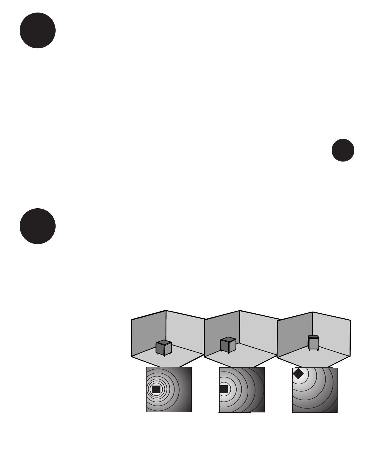
See Drawing 1 below. When you
place the V-80 well away from a wall,
it will produce bass at a certain level.
Move the V-80 close to the wall, it will
produce more output (about 3dB
more). Putting the subwoofer in a
corner will increase output another
3dB (6dB more than when placed
away from walls and corners).
All this technical jargon may sound
confusing, but it basically means that
you have a number of options, each of
which produces a different amount of
bass. For example, if you like a lot of
heavy bass, consider putting the V-80
into a corner. If you like smoother,
less-obvious bass, move the sub-
woofer out into the room. The main
thing to remember is that there is no
“right” or “wrong” place to put the
V-80 (assuming it’s less than six feet
from a wall receptacle). It all depends
on how much bass you want.
Another reason to experiment —
because low bass waves are very large
(up to forty feet or more across!), they
tend to cancel and reinforce each
other, causing places in the room
where there is lots of bass and others
where there isn’t very much at all. If
you walk around your listening room
while playing music, you’ll probably
discover these sorts of areas where
bass is either exaggerated or reduced.
Needless to say, if your main listening
area ends up in a “dead” space, you
will need to move the V-80 so that
bass is more normal.
Incidentally, moving the V-80
around won’t affect the stereo imaging
of your main stereo system, so feel
free to try various subwoofer positions.
Connecting the V-80 to
awall plug
The V-80 draws a moderately high
amount of current. Wedo not recom-
mend plugging it into a “convenience”
outlet (switched or unswitched) that
is often found on the back of receivers
and other stereo components.
Instead, connect the V-80 ONLYto
its own AC outlet. See items 8 and 9 in
the Safety Instructions at the beginning
of this manual.
Away from walls:
Normal bass
Against walls:
More bass
In Corner:
Most bass
Away from walls:
Normal bass
Against walls:
More bass
In Corner:
Most bass
DRAWING 1 - V-80 placement
Subwoofer
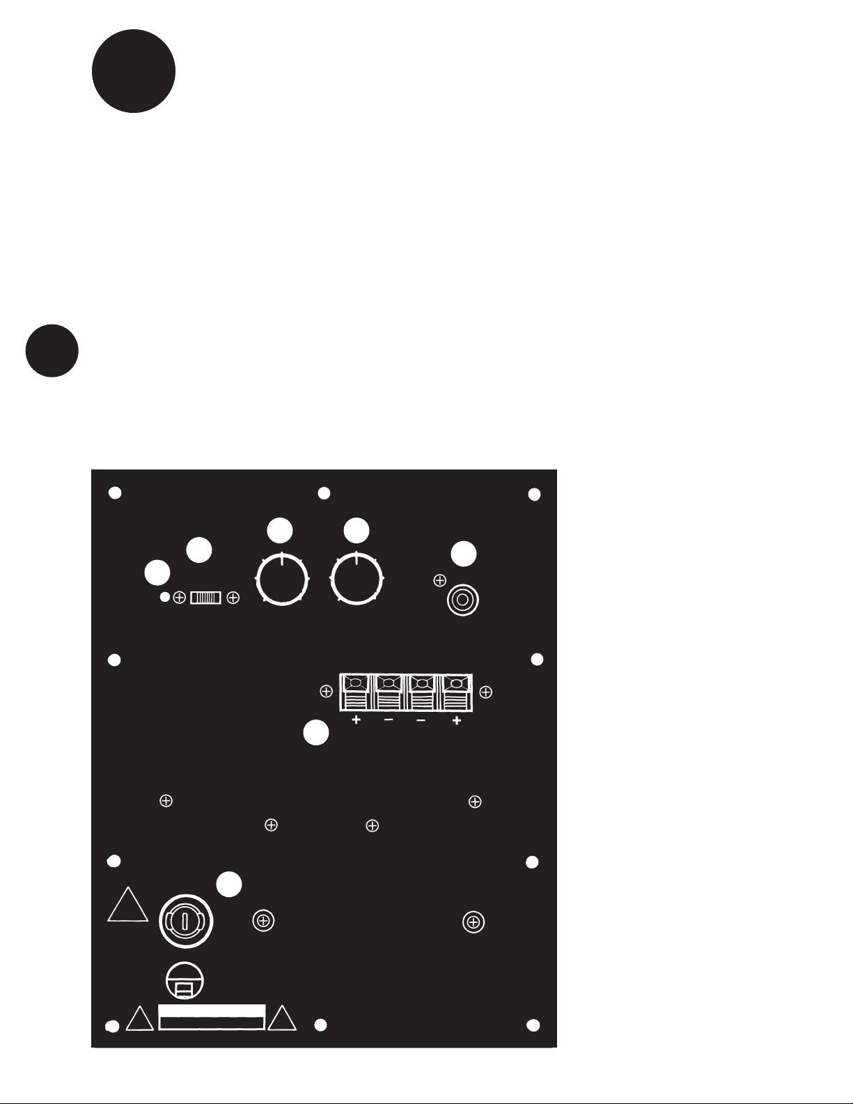
Amplifier Tour
Before actual hookup, you should
familiarize yourself with the connections
on the back of the subwoofer, as shown
in Figure 2 below.
1. POWER INDICATOR. When the
amplifier is ON, this indicator will be
green. When the amplifier is in the
STANDBY mode, as mentioned next,
this indicator will be red.
2. POWER/AUTO SWITCH. This
switch turns the amplifier on and off.
When the switch is in the ON position, the
amplifier will stay on as long as the
switch remains in that position. When this
switch is in the AUTO position, the ampli-
fier will stay turned on as long as a music
signal is being fed to the subwoofer
amplifier. This way, you don’t have to
remember to reach down and turn your
subwoofer on every time you listen to
music. Instead, the amplifier switches
itself on as soon as the music starts. If
you stop playing music after approximate-
ly 15 to 20 minutes, the amplifier goes
into STANDBY mode — see (1). When
you begin to play music again, the ampli-
fier will automatically turn on again.
We recommend that you turn the
amplifier on LAST,after you’ve turned on
your receiver/integrated amp/ reamp, CD
player, cassette deck, etc. Some compo-
nents send out loud, low-frequency
THUMPs when they are turned on. These
are not only startling and annoying, but
4
could also cause damage to your sub-
woofer if the volume control is turned
up high.
3. VOLUME control. Rotating this
knob clockwise increases the output level
of the subwoofer. To start out, make sure
that the VOLUME is turned all the way
down (fully counterclock-wise). Later,
after some initial listening tests, you can
adjust the volume to your own tastes.
However, care should be taken not to
overdrive the subwoofer to the point of
audible distortion.
4. FREQUENCY CONTROL. This con-
trol determines what lower part of the
frequency spectrum will be reproduced
by the V-80 and what higher parts will be
handled by your main speaker. It is a
“crossover” control. Rotating the knob
sets the point where all lower frequencies
will be handled by the subwoofer and all
higher frequencies will be routed to your
main stereo speakers.
To keep from affecting the stereo
imaging of your main speakers we rec-
ommend that the FREQUENCY control be
set at the lower frequency setting that
adds good bass and blends well with your
existing speakers. Typically, somewhere
between 80Hz and 100Hz is a good start-
ing point. You will need to experiment
with the setting that yields the best result
for your own particular speakers and
room.
5. LINE IN. This connection is used
ONLY if you have a preamplifier or a
receiver/integrated amplifier which has a
subwoofer output that follows the volume
control. More on this later.
6. HI LEVEL IN. Connects to your
receiver’s speaker terminals. These
spring type, color-coded connectors are
used to hook the amplifier to your receiv-
er if it does not have line level pre/main
connections. This is explained in the next
section.
7. REMOVABLE FUSE. This is the
power fuse. Under normal circumstances
it should not require any attention. If,
however, the unit will not turn on when
plugged into a known good 120 volt
outlet, the fuse should be removed and
checked. If it is determined to be bad
(open), you should have the unit
examined by your dealer or a qualified
service center.
POWER
1
2
3
5
6
7
OFF AUTOON
LEVEL LINE IN
HI LEVEL IN
LEFT RIGHT
C
4
Figure 2
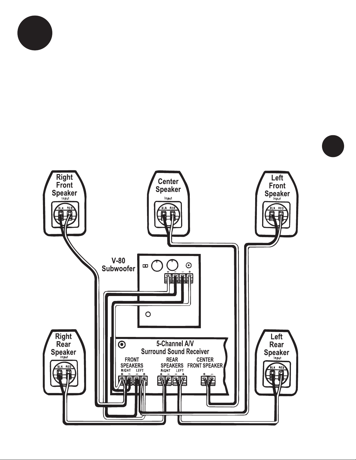
HOOKUP
Speaker Wire Tips
Aword about speaker wire – There
are a number of quality speaker wire
products available today. Most of these
products offer obvious sonic benefits over
lamp cord and light gauge wires. B.I.C
Speaker Systems come equipped with
inputs that allow the greatest flexibility
and choice of hookup wire and connec-
tors. The choice of speaker wire is depen-
dent on the type of amplifier, the distance
you intend to run the wire, and your bud-
Figure 3 - Speaker Level Hookup
5
get, among other things. If in doubt as to
which brand or type of wire and connec-
tor to use, consult your audio dealer.
Most speaker wire is polarity coded. This
means that each conductor is labeled
either (+) positive or (-) negative. The
(+) positive side may be a different color
or texture than the (-) negative side. On
the back of your amplifier, each channel
is probably labeled (+) and (-) as well
as color coded red for (+) positive and
black for (-) negative. B.I.Cspeaker
terminals are color coded red for (+)
positive and black for (-) negative. Be
sure to hook (+) to (+), (red to red),
and (-) to (-), (black to black).
All connections should be tight and close
fitting. Inspect connections for frays and
stray strands of wire touching both (+)
and (-) terminals. (This will cause a short
and, perhaps, damage your equipment.)
Hooking Up Your
New V-80 Subwoofer
STOP! — Make sure that you consult your
amplifier’s owner’s manual regarding
speaker hookup. Your amplifier should
be turned off throughout this procedure.
D
Hookup
Two basic connection options
IMPORTANT: Make certain all stereo
system components including the
Power Point subwoofer are turned OFF
before proceeding.
1. Amplifier/speaker level hookup
If you own a receiver or integrated
6
amplifer that does NOT have a line level
subwoofer output or preamp output,
refer to Figure 3 for proper connection.
To determine if your equipment has a
subwoofer output, look on the back of
the receiver for a female RCA type jack
labeled “subwoofer out,” “sub out” etc.
If your receiver does have a subwoofer
output go to hookup 2 below.
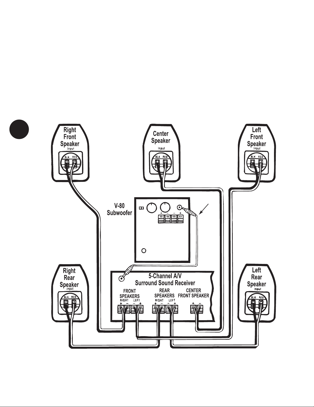
2. Line level (subwoofer) hookup
If your receiver or integrated amplifier
DOES have a subwoofer output, refer to
Figure 4 for proper connection. This
hookup method will require a long
(depending on the location of your
receiver and subwoofer) male RCA to
RCA line level cable to connect the
subwoofer. The satellites connect to
the receiver as shown.
Figure 4 - Line Level Hookup
RCA LINE
CORD
SUBWOOFER
SUB OUT

ments) through it. This will
negatively affect the stereo imag-
ing of your main speakers. Back
the FREQUENCY setting off until
you hear only bass from the V-80.
If the FREQUENCY control is set
too low, you simply won’t get
much output from the subwoofer.
Move it back closer to 80Hz.
o
o8. After you are satisfied with the
output of your subwoofer, you
can make all your volume settings
through your main stereo sys-
tem’s volume control. The only
time you might want to re-adjust
the subwoofer’s VOLUME is when
you encounter a musical selection
that has abnormally low – or high
– bass.
You can leave the subwoofer turned on
and in STANDBY mode when not in use.
It does not draw much power in this state
and will be ready to add low bass the
moment you begin to play music.
Remember, you don’t have to do anything
except leave the POWER switch in the
AUTO position. The subwoofer will auto-
matically go into STANDBY mode after 15
to 20 minutes, when no music is playing.
However, if you’re not using your stereo
system for a long period of time (such as
when you’re on vacation), turn the
POWER switch to the OFF position FIRST,
before your other components.
A Word About
Power Handling
Usually if distortion is heard when the
speakers are being driven at loud levels,
it is caused by driving (turning up) the
amplifier too loud and not driving the
speakers with more power than they can
handle. Remember, most amplifiers put
out their full rated power well before the
volume control is turned all the way up!
If your speakers distort when you play
them loud, turn down the amplifier or get
a bigger one. B.I.C Speaker Systems are
designed to the highest possible value
and performance standards. Our confi-
dence in their quality is such that B.I.C
America offers customers a transferable
limited warranty as explained on page 8.
Caring for Your
B.I.C Speaker
The subwoofer cabinet is finished with a
very high quality polymer laminate cover-
INITIAL
LISTENING
TEST
o
o1. Double-check all connections.
o
o2. Make sure that the volume
controls on both the subwoofer
and your receiver/integrated
amp/preamp are turned
all the way down (fully counter-
clockwise). Set the frequency
control to 80 Hz.
o
o3. Turn on your stereo system.
THEN turn on the subwoofer.
Confirm that the green POWER
indicator is glowing. If it isn’t,
check the power connections
between the subwoofer and the
wall socket.
o
o4. Play a musical selection that you
are familiar with. Pick a song
that has regular low bass beats.
Advance the receiver/integrated
amp/preamp’s volume control
up to a normal listening level. If
you don’t hear sound through
your main speakers, turn off the
system and check connections.
o
o5. If sound is indeed coming out of
your main speakers, turn the
subwoofer’s VOLUME control
clockwise until you hear notice-
able additional bass. If you don’t
hear bass by the time you have
advanced the subwoofer’s VOL-
UME control halfway, turn off the
system and check connections.
o
o6. Adjust the subwoofer’s VOLUME
control until you are satisfied
with the amount of bass. You
may want to try several different
compact discs while determining
how high to adjust the subwoofer
VOLUME. The amount of bass
varies from disc to disc and
between different types of music.
o
o7. Change the FREQUENCY control
to higher and lower settings.
If the FREQUENCY control is set
too high, you’ll start to hear low
midrange (voices and instru-
ing that is both attractive and serves as an
excellent protection for the wood cabinet.
The system can be cleaned with a damp, soft
cloth or you may use a high-quality furniture
polish to maintain the original luster.
Troubleshooting
Before returning your V-80 for service,
you can save time (and often embarrass-
ment) by checking for a few problems that
are most often encountered.
Power light is not lit. No sound.
1. Is your V-80 plugged in to a live
AC wall socket?
2. Is the power switch on?
3. Has the V-80 overheated and shut off
temporarily?
No sound from either set of
speakers.
1. Are your other components turned on?
2. Is the receiver or preamp set to the
appropriate input and is that sound source
playing?
3. Do you have an unconnected tape moni-
tor selected?
4. Is the V-80 correctly connected to your
receiver, preamplifier or integrated amplifier?
Sound comes from main
speakers but not subwoofer
1. Is the V-80’s VOLUME control turned
up?
2. Check the speaker connections for
small strands of wire touching both terminals.
Sound comes from the
subwoofer but not your main
speakers
1. Check the connections between
the V-80 and your main or satellite speakers.
2. If you have used the line level hookup
method...
• confirm that the power amplifier is
turned on.
• check the RCA patch cord
• check the speaker wire connections
between the power amplifier and
main or satellite speakers.
7
E
F

V-80 Powered Subwoofer
Limited Warranty
If the
B.I.C Speaker system proves to be
defective in materials or workmanship
within five years (two years for the elec-
tronic amplifier) from the date of the
original customer’s purchase, we will, at
our option, repair or replace the defec-
tive product. If for any reason, we are
unable to repair or replace a defective
product within a reasonable time, we will
refund your purchase price.
*DISCLAIMER
THE WARRANTY STATED HEREIN IS IN LIEU
OF ALL OTHER WARRANTIES, EXPRESS OR
IMPLIED, INCLUDING MERCHANTABILITY
AND FITNESS FOR PARTICULAR PURPOSE AND
ALL OTHER LIABILITIES AND OBLIGATIONS
OF B.I.C AMERICA, ALL OF WHICH ARE
EXPRESSLY DISCLAIMED. B.I.C AMERICA HAS
NOT MADE AND DOES NOT HEREBY MAKE
ANY OTHER REPRESENTATION, WARRANTY
OR COVENANT WITH RESPECT TO THE
CONDITION, QUALITY, DURABILITY, DESIGN,
OPERATION, CAPACITY, FITNESS FOR USE OR
SUITABILITY OF THE SPEAKER SYSTEMS.
Exclusion of
Certain Damages
B.I.C America’s liability for any defective
product is limited to repair or replace-
ment of the product at our option. B.I.C
America shall not be liable for incidental
or consequential damages of any kind or
character because of product defects.
Some states do not allow limitations
on how long an implied warranty lasts
and/or do not allow the exclusion or lim-
itation of incidental or consequential
damages, so the above limitations and
exclusions may not apply.
This Warranty Does
Not Cover:
Damage caused by abuse, accident, mis-
use, negligence, or improper operation.
Products that have been altered or
modified.
Any product whose serial number has
been altered, defaced, or removed.
Normal wear and maintenance.
Damages caused by shipping. (All claims
for shipping damage must be made with
the carrier.)
©2012 B.I.C America
Warranty Service
Warranty service must be performed
by an authorized service center, usually
a B.I.C Speaker Systems dealer or its
authorized agent. You may obtain a list
of authorized service centers by writing
to the address below.
All warranty repairs must be accompan-
ied by the original bill of sales. No other
document is acceptable or is required.
This warranty gives you specific legal
rights, and you may also have other rights
which vary from state to state.
Due to our continual efforts to improve product
quality as new technology and techniques become
available, B.I.C America reserves the right to revise
its Speaker Systems specifications without notice.
8
V-80 Specifications
8˝ long-throw woofer, auto on/off, vented
Enclosure . . . . . . . . . . . . . . . . . . . . . . . . . . . .Vinyl laminated
Dimensions . . . . . . . . . . . . . . . .1215/16˝ H x 111/4˝ W x 111/4˝ D
Power . . . . . . . . . . . . . . . . . . . . . . . . . . . . . . . . . . .100 watts
Subsonic Filter . . . . . . . . . . . . . . . .12 dB/octave below 20 Hz
Crossover . . . . . . . . . . . . . . . . . . .40-180 Hz (user variable)
Line Level Sensitivity . . . . . . . . . . . . . . . . . . . . . . . . . . .28 mv.
Speaker Level Sensitivity . . . . . . . . . . . . . . . . . . . . . . .347 mv.
Power Requirements . . . . . . . . . . . . . . . . . . . . . . . .180 watts
Frequency Response . . . . . . . . . . . . . . . . . . .38 Hz - 180 kHz
Characteristic Sensitivity . . . . . . . . . .90 dB @ 1 watt, 1 meter
Bass is muffled or weak
1. Check speaker wire polarity of all
connections.
2. Reposition your subwoofer. At
some points in the room, its output
may be cancelled by the geometry of
the room. Moving the V-80 can elimi-
nate this problem.
Please refer to Item 10 in the Safety
Instructions for conditions that ALWAYS
require service by qualified personnel.
If you have tried all the above and
still cannot get the V-80 to operate
properly, consult your dealer or call
B.I.C.
G
H
B.I.C America
925 N. Shepard Street
Anaheim, CA 92806
www.bicamerica.com
Contact your dealer for warranty
repair or technical help, or
call
1-877-558-4242 (4BIC) for Tech Support.
Table of contents
Other BIC Subwoofer manuals

Popular Subwoofer manuals by other brands


Power bass
Power bass XL-844 Application guide

Cambridge Sound Works
Cambridge Sound Works Newton II Series user manual

d & b audiotechnik
d & b audiotechnik Qi-SUB manual

Phase Technologies
Phase Technologies PC-SUB WL-8 Owner's Manual & Installation Instructions

Audio Control
Audio Control Spike Series user guide

Phase Technologies
Phase Technologies IW-200 installation guide

d & b audiotechnik
d & b audiotechnik E Series manual

ART+SOUND
ART+SOUND FL-A80 operating manual

AER
AER combi-SUB 12 user manual

d & b audiotechnik
d & b audiotechnik t-sub manual

Diamond Audio Technology
Diamond Audio Technology TDX 10D2 owner's manual

MB QUART
MB QUART PREMIUM PWE 254 PWE254 PWE254 installation manual