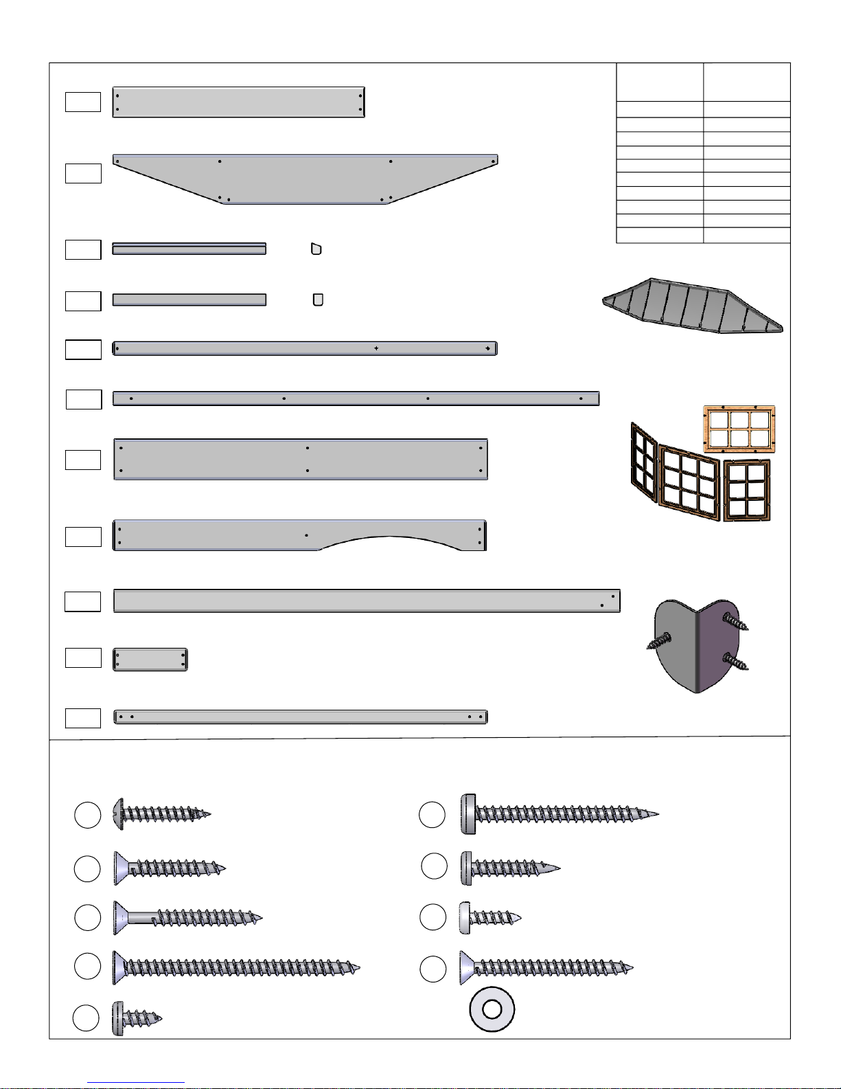
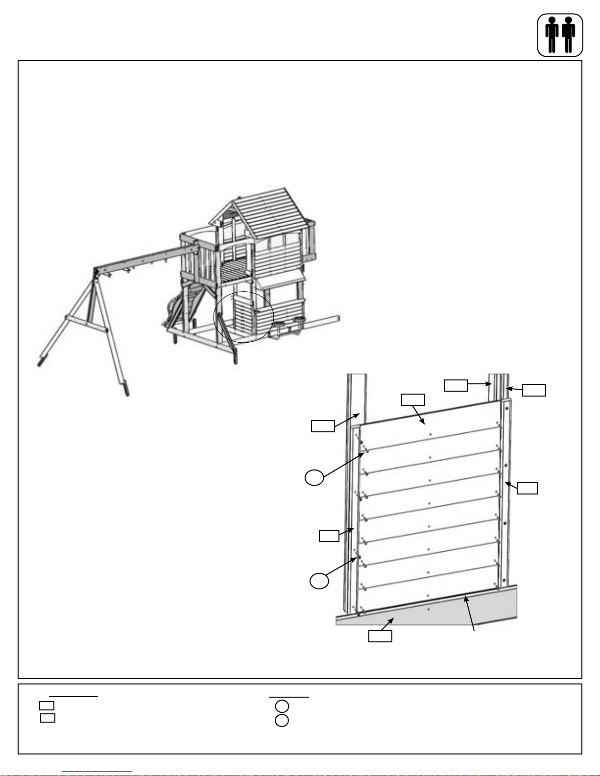
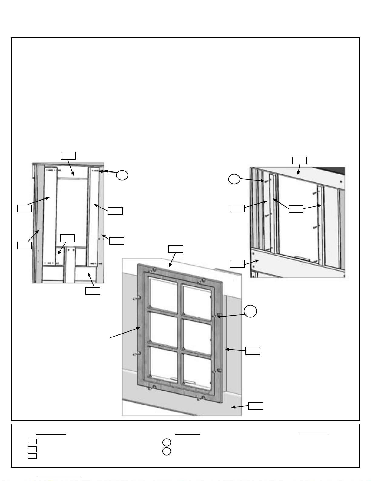
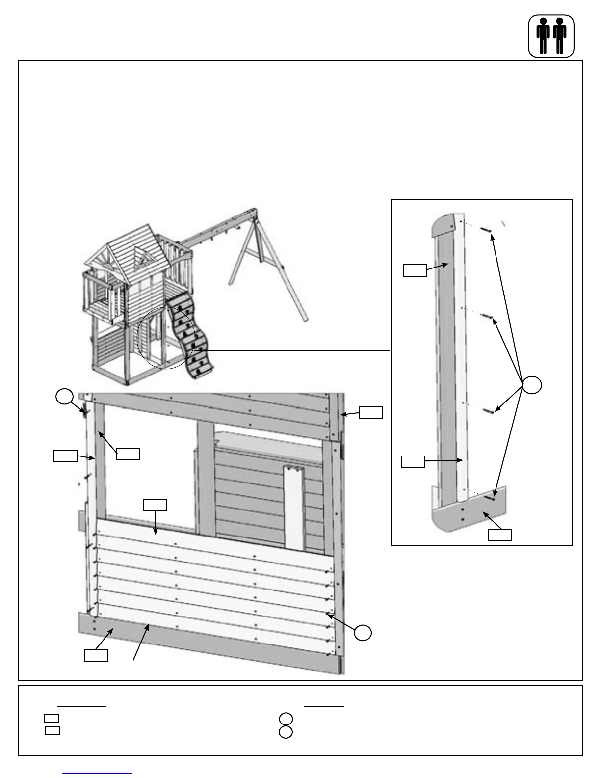
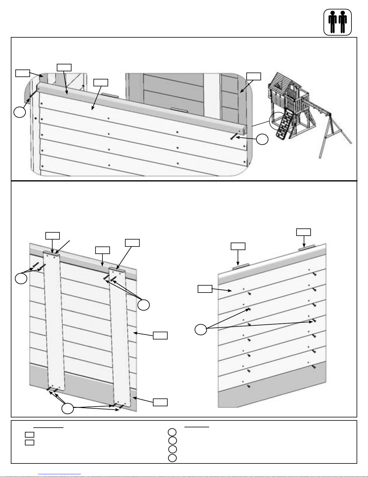
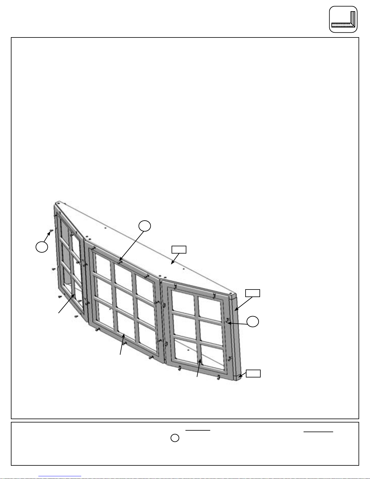
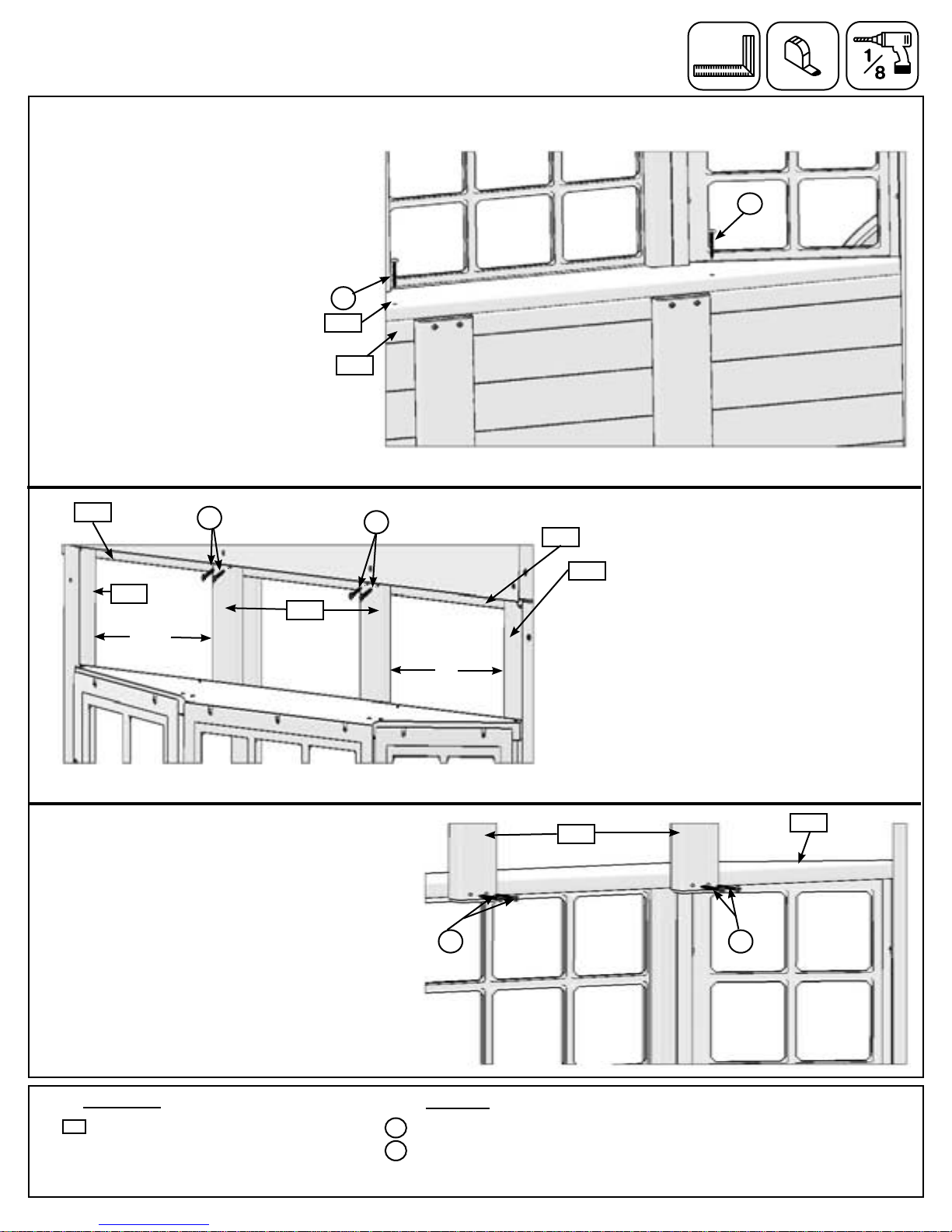
Big Backyard DELUXE LOWER CLUBHOUSE F24700 User manual

INSTALLATION AND OPERATING INSTRUCTIONS
8 - 10 Hrs
To reduce the risk of serious injury or death, you must read and
follow these instructions. Keep and refer to these instructions
often and give them to any future owner of this play system. Manufacturer contact information provided below.
OBSTACLE FREE SAFETY ZONE - 32’7” x 28’ (9.9 x 8.5 m) area requires Protective Surfacing. See page 3.
MAXIMUM VERTICAL FALL HEIGHT - 6’11” (2.1 m)
CAPACITY - 12 Users Maximum, Ages 3to 10; Weight Limit 110 lbs. (49.9 kg) per child.
RESIDENTIAL HOME USE ONLY. Not intended for public areas such as schools, churches, nurseries,
day cares or parks
Rev 01/13/2011
3404700SV
Two person
assembly
Table of Contents
Warnings and Safe Play Instructions .......... pg. 2
Protective Surfacing Guidelines .............. pg. 3
Instructions for Proper Maintenance .......... pg. 4
About Our Wood – Limited Warranty.......... pg. 5
Keys to Assembly Success.................. pg. 6
Part ID .................................. pg. 7
Installation of I.D./Warning Plaque........ Final Step
WARNING
18’ 8” (5.7 m)
14’ 5” (4.4 m)
Solowave Design
375 Sligo Rd. West, PO Box 10
Mount Forest, ON Canada N0G 2L1
General Inquiries:
8:00am - 4:30pm EST
Toll Free: 1-877-966-3738
DELUXE LOWER CLUBHOUSE – F24700
for use with SUMMERVILLE PLAY SYSTEM – F23105

(1) CE Floor Board 1 x 4 x 32-1/2"
3630304 Box 1A
D1
(2) Window Frame 1 x 2 x 15-1/4"
3631479 Box 1A
D7
(2) Door Trim 1 x 2 x 26-1/8"
3631480 Box 1A
D8
(2) Lower Window 1 x 5 x 22-3/4"
3631481 Box 1A
D9
(8) Siding 3/8 x 3-1/2 x 20"
3631484 Box 1A
D12
3631485 Box 1A
D13
(1) CE Wall Board 1 x 4 x 22-3/4"
D5
(1) Window Spacer 1 x 1-1/2 x 42-1/2"
3631476 Box 1A
3630705 Box 1A
(2) Cedar Wall 1 x 4 x 23½"
D2
3631475 Box 1A
(1) Lower Wall Top 5/4 x 4 x 36"
D4
D3
3631415 Box 1A
(2) Lower Trim 1 x 2 x19-5/8"
D11
3631483 Box 1A
(6) Siding 3/8 x 3-1/2 x 38-3/4"
3631482 Box 1A
D10
(9) Siding 3/8 x 3-1/2 x 42-5/8"
3631477 Box 1A
(2) Trim 1 x 2 x 50-1/2"
D6
Nominal Size
2" x 6"
2" x 4"
2" x 3"
2" x 2"
5/4" x 4"
5/4" x 5"
5/4" x 6"
1" x 6"
1" x 5"
1" x 4"
1" x 2"
Actual Size
1½" x 5
⅜
"
1
⅜
" x 3
⅜
"
1
⅜
" x 2½"
1½" x 1½"
1" x 3½"
1" x 4½"
1" x 5½"
⅝" x 5
⅜
"
⅝" x 4½"
⅝" x 3
⅜
"
⅝" x 1
⅜
"
Part Identification (Reduced Part Size)

(1) Cafe Support 2 x 2 x 41-1/2"
3641495 Box 1A
D24
(2) Window Block 2 x 3 x 8-1/4"
3641494 Box 1A
D23
(1) Door Post 5/4 x 3 x 56-1/4"
3641493 Box 1A
D22
D21
(1) Door Top 1 x 4 x 41-1/2"
3641492 Box 1A
D20
3641491 Box 1A
(1) Ground Divider 1 x 5 x 41-1/2"
D19
3641490 Box 1A
(2) Lower Mid Post 2 x 2 x 54"
D18
3641489 Box 1A
(1) Window Sill 2 x 2 x 42-3/4"
3641488 Box 1A
(2) Window Support B 5/4 x 2 x 17"
D17
(4) Window Support A 5/4 x 2 x 17"
3641487 Box 1A
D16
(2) Cedar Wall 1 x 4 x 28"
3635265 Box 1A
D14
D15
3641486 Box 1A
(2) Window Bottom Top 5/4 x 6 x 42 3/4"
S2
(50) Flat Head Screw #8 x 1 1/2" (9260512)
S3
(22) Flat Head Screw #8 x 2 1/2" (9260522)
S7
(6) Pan Screw #12 x 2" (9294620)
S5
(4) Pan Screw #8 x 1/2" (9264504)
S1
(26) Flat Head Screw #8 x 1 1/8" (9290514)
(84) Truss Screw #8 x 7/8" (9229505)
S0
S15
(12) Flat Head Screw #8 x 1-3/4" (9260513)
S13
(34) Pan Screw #6 x 5/8" (9264990)
S10
(4) Pan Screw #8 x 1" (9264510)
(1) Corner Brace with hardware
(2pk)
9201100 Box 1A
(1) 3320150 Clubhouse
Bay Roof -Green
(1) 3320149 Stoneybrook
Lodge Clubhouse Bay
Window Set-Green
(4) #8 Flat Washer (9251500)
Actual Size
1½" x 5
⅜
"
1
⅜
" x 3
⅜
"
1
⅜
" x 2½"
1½" x 1½"
1" x 3½"
1" x 4½"
1" x 5½"
⅝" x 5
⅜
"
⅝" x 4½"
⅝" x 3
⅜
"
⅝" x 1
⅜
"
Nominal Size
2" x 6"
2" x 4"
2" x 3"
2" x 2"
5/4" x 4"
5/4" x 5"
5/4" x 6"
1" x 6"
1" x 5"
1" x 4"
1" x 2"
Part Identification (Reduced Part Size)
Part Identification (Actual Part Size)

PRODUCT NUMBER: F24700
CARTON I.D. STAMP: __ __ __ __ __ 14459 ___ (Box 1)
CARTON I.D. STAMP: __ __ __ __ __ 14459 ___ (Box 2)
CARTON I.D. STAMP: __ __ __ __ __ 14459 ___ (Box 3)
CARTON I.D. STAMP: __ __ __ __ __ 14459 ___ (Box 4)
CARTON I.D. STAMP: __ __ __ __ __ 14459 ___ (Box 5)
CARTON I.D. STAMP: __ __ __ __ __ 14459 ___ (Box 6)

Step 43: Cafe Canopy Assembly
A: Feed all canopy frames through the pockets of the canopy. (g. 43.1)
B: Place the frames together so the U-Frame is inside, then the Z-Frame and lastly the P-Frame on the outside
and then attach with 1 (S19) #12 x 1/2” Pan Bolt (with #12 lock nut) per side. (g. 43.2 & 43.3)
C: At the back of the fort, in between (C13) Post and (C15) Mid Post attach each Z-Frame to the (C21) Floor
Gap with 1 (S6) #12 x 1” Pan Screw per frame. (g. 43.5)
D: From underneath the fort, attach canopy to (C21) Floor Gap with 5 (S5) #8 x 1/2” Pan Screws (with #8 at
washer). (g. 43.7)
E: Attach each P-Frame to (C13) Post and (C15) Mid Post, through the tarp, with 1 (S6) #12 x 1” Pan Screw and
2 (S5) #8 x 1/2” Pan Screws (with #8 at washer) per side. (g. 43.6)
Frame P
Frame Z
Frame U
P
U
Z
S19
Fig. 43.1
Fig. 43.2
Fig. 43.3
Fig. 43.4
Fig. 43.5
Fig. 43.7
S6
C21
P
Z
Under canopy view
P
Z
Hardware
2 x #12 x 1/2” Pan Bolt (with #12 lock nut)
9 x #8 x 1/2” Pan Screw (with #8 at washers)
4 x #12 x 1” Pan Screw
S19
S5
Other Parts
S6
1 x Canopy
S6
Fig. 43.6
PC15
S5
B20
B20
C13
Canopy removed
for clariity
5
x 1 per side
x 1 per side
x 2 per side
x 1 per side
S5
SL Ground
removed for
clarity
Canopy removed
for clarity
U

Step 44: Cafe Wall Assembly
A: On the (C13) Post below the Cafe Canopy attach 1 (B4) Lower Trim ush to the edge of the post and tight to
the top of (B16) Ground Front Back with 3 (S2) #8 x 1-1/2” Wood Screws. (g. 44.1)
Fig. 44.1
B4
C13
B16 Tight to bottom
1 x Lower Trim 1 x 2 x 19-5/8”
B4
Hardware
Wood Parts
3 x #8 x 1-1/2” Wood Screw
S2
6
S2

B: Starting tight to the top of (B16) Ground Front Back and tight to the side of (B4) Lower Trim attach 1 (B9)
Siding to (C13) Post and (C15) Mid Post with 2 (S0) #8 x 7/8” Truss Screws per siding. (g. 44.2)
C: Attach 5 more (B9) Siding to (C13) Post and (C15) Mid Post with 2 (S0) #8 x 7/8” Truss Screws per siding.
Making sure the top board overlaps the bottom board. (g. 44.2)
D: On (C15) Mid Post, tight to the sides of (B9) Siding and tight to the top of (B16) Ground Front Back, attach (B4)
Lower Trim with 3 (S2) #8 x 1-1/2” Wood Screws. (g. 44.3)
Fig. 44.2
Fig. 44.3
S0
Leave middle
holes open
S2
B4
C13
B4
B16
Step 44: Cafe Wall Assembly cont.
1 x Lower Trim 1 x 2 x 19-5/8”
6 x Siding 3/8 x 3-1/2 x 42-5/8”
B4
HardwareWood Parts
12 x #8 x 7/8” Truss Screw
3 x #8 x 1-1/2” Wood Screw
S0
S2
B9
C15
B9
S0 x 6
x 6
B9
7
C15
B16
SL Ground
removed for
clarity

Step 45: Table Top Assembly
A: Place (B21) Table Support ush to the notched out extension of (A11) Table Top as shown in g. 45.2 and
attach using 5 (S7) #12 x 2” Pan Screws. Notice the sizing of the notches and their placement.
B: Place Table Top Assembly tight to the top of (B9) Siding and the notches in (A11) are tight against (C13)
Post and (C15) Mid Post. Attach Table Top Assembly to each post using 2 (S3) #8 x 2-1/2” Wood Screws per
post. (g. 45.3)
Fig. 45.1
Fig. 45.2
S7
Fig. 45.3
A11
B21
S3
C15
B4
C13
1 x Table Support 2 x 2 x 45-1/2”
1 x Table Top 5/4 x 6 x 45-1/2”
B21
HardwareWood Parts
5 x #12 x 2” Pan Screw
4 x #8 x 2-1/2” Wood Screw
S7
S3
A11
B9
B4
A11
8
Flush to edges
Underneath View
Longer Notch
Shorter Notch
SL Ground
removed for clarity
Longer Notch
Shorter Notch
S3

Step 45: Table Top Assembly cont.
C: From the inside of the fort, tight to the bottom
of (A11) Table Top and centred over the pilot holes
in (B9) Siding, attach both (B1) Cedar Walls to
(B21) Table Support with 2 (S2) #8 x 1-1/2” Wood
Screws per board and to (B16) Ground Front Back
using 2 (S1) #8 x 1-1/8” Wood Screws per board.
(g. 45.4)
D: From the outside of the fort attach both (B1)
Cedar Walls to the (B9) Siding with 12 (S0) #8 x
7/8” Truss Screws (2 per siding). (g. 45.5)
Fig. 45.4
B1
Fig. 45.5
B16
B21
Centre over pilot
holes in (B9) Siding
2 x Cedar Wall 1 x 4 x 23-1/2”
B1
HardwareWood Parts
4 x #8 x 1-1/8” Wood Screw
4 x #8 x 1-1/2” Wood Screw
12 x #8 x 7/8” Truss Screw
S2
S0
x 12
S2
S1
S1
S1
B9
A11
B9
9
S0
S2

Step 46: Stool Seat Assembly
A: Using the hardware provided with the Stool Seat Assembly attach 1 Seat to 1 Seat Support and then create a
second seat as in g. 46.1.
B: Keeping the Cross Brace tight to the Seat Assemblies, fasten the Cross Brace to each of the Seat Assemblies
using the hardware provided. (g. 46.2)
C: Attach the Stool Seat Assembly to (B16) Ground Front Back using 2 (PX2) 1/4 x 1-1/4” Pan Bolt (with 4 at
washers and 1 lock nut) per Seat Assembly. (g. 46.3)
B16
Fig. 46.1
Fig. 46.2
Fig. 46.3
1/4” Flat washer
Seat
Seat Support
Spacer
1/4-20 x 1”
Machine Screw
1/4-20 x 1-1/4”
Machine Screw
Steel Cross Brace
1/4-20 Lock Nut
Pieces removed
for clarity
Hardware
1 x Stool Set (with hardware)
Other Parts
10
4 x 1/4 x 1-1/4” Pan Bolt
(1/4” at washer x 4, 1/4” lock nut)
PX2
G4
(2) Hex Bolt 5/16 x 4"
9277340
5/16" Lock Washer - 5/16" Flat Washer - 5/16" T-Nut
H3
(8) Hex Bolt 1/4 x 2 1/2"
9277222
1/4" Lock Washer - 1/4" Flat Washer - 1/4" T-Nut
H7
(4) Hex Bolt 1/4 x 5 1/2"
9277252
1/4" Lock Washer - 1/4" Flat Washer - 1/4" T-Nut
G5
(7) Hex Bolt 5/16 x 4 1/2"
9277342 5/16" Lock Washer - 5/16" Flat Washer - 5/16" T-Nut
1/4" Lock Washer - 1/4" Flat Washer - 1/4" T-Nut
(12) Hex Bolt 1/4 x 4"
9277240
H4
G1
(4) Hex Bolt 5/16 x 1 1/2"
5/16" Lock Washer - 5/16" Flat Washer - 5/16" T-Nut
9277312
H2
(2) Hex Bolt 1/4 x 2"
9277220
1/4" Lock Washer - 1/4" Flat Washer - 1/4" T-Nut
H8
(1) Hex Bolt 1/4 x 4 1/4"
9277241
1/4" Lock Washer - 1/4" Flat Washer - 1/4" T-Nut
Hardware Identification (Actual Size)
H11
(6) Hex Bolt 1/4 x 2 3/4"
9277223
1/4" Lock Washer - 1/4" Flat Washer - 1/4" T-Nut
H6
(4) Hex Bolt 1/4 x 4 3/4
9277243
1/4" Lock Washer - 1/4" Flat Washer - 1/4" T-Nut
H5
(6) Hex Bolt 1/4 x 4 1/2"
9277242
1/4" Lock Washer - 1/4" Flat Washer - 1/4" T-Nut
H13
(8) Hex Bolt 1/4 x 3 1/2"
9277232
1/4" Lock Washer - 1/4" Flat Washer - 1/4" T-Nut
PL2
(4) Pan Bolt 1/4 x 1 1/4"
1/4" Lock Washer - 1/4" Flat Washer
1/4" T-Nut
9274211
PX2 - Pan Bolt Assembly
PX2

Step 47: Entrance Wall Assembly
Fig. 47.1
Fig. 47.2
11
2 x Lower Mid Post 2 x 2 x 54”
Hardware
Wood Parts
8 x #8 x 2-1/2” Wood Screw
S3
D19
C15
S3
C15
D19
A: Attach 1 (D19) Lower Mid Post ush to the bottom and outer edge of each (C15) Mid Post with 4 (S3) #8 x
2-1/2” Wood Screws per board. (g. 47.2)
D19 Part of fort
removed for clarity
S3

15-7/8"
15-7/8"
Step 47: Entrance Wall Assembly cont.
B: Flush to the top and tight to each (B16) Ground Front and Back attach 1 (D20) Ground Divider to each (C15)
Mid Post with 4 (S2) #8 x 1-1/2” Wood Screws. (g. 47.3)
C: Attach 1 (D21) Door Top tight to the bottom of (B20) Floor Front Back to each (C15) Mid Post with 4 (S2) #8 x
1-1/2” Wood Screws. (g. 47.4)
D: Measure 15-7/8” from inside of (D19) Lower Mid Post and attach 1 (D22) Door Post to (D21) Door Top with 1
(S2) #8 x 1-1/2” Wood Screw and to (D20) Ground Divider with 2 (S2) #8 x 1-1/2” Wood Screws. (D22) Door Post
should be tight to (C19) Floor Joist. (g. 47.4)
E: From the inside of the fort attach (D22) Door Post to (C19) Floor Joist with 2 Corner Braces using the included
hardware. 1 Corner Brace goes on each side of the (D22) Door Post. (g. 47.5)
F: Tight to the top of (D20) Ground Divider and tight to outside edge of (D19) Lower Mid Post, attach 1 (D8) Door
Trim to (C15) Mid Post with 4 (S2) #8 x 1-1/2” Wood Screws. (g. 47.4)
Fig. 47.5
12
1 x Door Post 5/4 x 3 x 56-1/4”
1 x Door Top 1 x 4 x 41-1/2”
1 x Door Trim 1 x 2 x 26-1/8”
1 x Ground Divider 1 x 5 x 41-1/2”
Hardware
Wood Parts
15 x #8 x 1-1/2” Wood Screw
S2
D22
D8
C15
D21
D20
D8
C15
S2
D19
D22
Fig. 47.4
D21
15-7/8"
15-7/8"
S2
D19
S2
D20 S2
S2
Corner Braces
with Hardware
Fig. 47.3
C15
C15
B16
B16
C19
B20
D20
Other Parts
2 x Corner Brace (with hardware)
Note: The Access
Ladder and Rock
Rail may need to be
removed to attach
(D21) Door Top
B20

G: Starting tight to the top of (D20) Ground Divider and tight to the side of (D8) Door Trim attach 1 (D12) Siding to
(D19) Lower Mid Post and (D22) Door Post with 2 (S0) #8 x 7/8” Truss Screws. (g. 47.7)
H: Attach 7 more (D12) Siding to (D19) Lower Mid Post and (D22) Door Post with 2 (S0) #8 x 7/8” Truss Screws
per siding. Making sure the top board overlap the bottom board. (g. 47.7)
I: Tight to the top of (D20) Ground Divider and tight to the (D12) Siding attach 1 (D8) Door Trim to (D22) Door Post
with 4 (S2) #8 x 1-1/2” Wood Screws. (g. 47.7)
Fig. 47.7
Hardware
Wood Parts
13
Step 47: Entrance Wall Assembly cont.
Fig. 47.6
8 x Siding 3/8 x 3-1/2 x 20”
1 x Door Trim 1 x 2 x 26-1/8”
16 x #8 x 7/8” Truss Screw
4 x #8 x 1-1/2” Wood Screw
S0
D12
D8
D8
C15
D12
S0
D22
x 8 per side
Start at bottom
D19
D8
D20
S2 x 4
S2
Access Ladder
removed for clarity

J: Tight to the top of (D12) Siding, attach 1 (D9) Lower Window to (C15) Mid Post and (D22) Door Post
with 4 (S2) #8 x 1-1/2” Wood Screws . (g. 47.8)
K: From the inside and ush to the top of (D9) Lower Window and centred over the pilot holes in (D12)
Siding, attach (D1) CE Floor Board to (D20) Ground Divider and (D9) Lower Window with 4 (S1) #8 x
1-1/8” Wood Screws. (g. 47.9)
L: From outside of the fort attach (D1) CE Floor Board to each (D12) Siding using 8 (S0) #8 x 7/8” Truss
Screws (1 per siding). (g. 47.8)
Step 47: Entrance Wall Assembly cont.
1 x CE Floor Board 1 x 4 x 32-1/2”
1 x Lower Window 1 x 5 x 22-3/4”
Hardware
Wood Parts
8 x #8 x 7/8” Truss Screw
4 x #8 x 1-1/8” Wood Screw
4 x #8 x 1-1/2” Wood Screw
S0
D1
D9
S2
S1
14
D9
S2
S2
Fig. 47.8
Fig. 47.9
S1
D1
D22
D19
C15
S1
S0
D9
x 8
Outside View
Inside View
D12
Access Ladder
removed for clarity

A: From inside the fort, tight to the bottom of (D9) Lower Window and inside edge of (D19) Lower Mid Post attach
1 (D9) Lower Window to (D21) Door Top and (D9) Lower Window with 4 (S1) #8 x 1-1/8” Wood Screws. (g. 48.1)
B: Tight to the bottom of (D9) Lower Window and inside edge of (D22) Door Post attach 1 (D13) CE Wall Board to
(D21) Door Top and (D9) Lower Window with 4 (S1) #8 x 1-1/8” Wood Screws. (g. 48.1)
C: From outside the fort, tight to top of (D9) Lower Window and ush to inside edge of (D13) CE Wall Board attach
1 (D7) Window Frame to (D13) CE Wall board with 3 (S1) #8 x 1-1/8” Wood Screws. (g. 48.2)
D: Attach a second (D7) Window Frame ush to the edge of (D9) Lower Window with 3 (S1) #8 x 1-1/8” Wood
Screws. (g. 48.2)
E: In the opening place 1 - 6-Pane Window and attach to (D21) Door Top and (D9) Lower Window and each (D7)
Window Frames with 8 (S13) #6 x 5/8” Pan Screws. (g. 48.3)
Step 48: Window Assembly
15
S1
Outside View
Inside View
D21
D13
D19
D9
x 4 per board
D22
D12
Fig. 48.1
Fig. 48.2
Fig. 48.3
S1
D9
D13
D21
D7
x 3 per side
D9
D7
S13
D21
x 8
2 x Window Frame 1 x 2 x 15-1/4”
1 x CE Wall Board 1 x 4 x 22-3/4”
1 x Lower Window 1 x 5 x 22-3/4”
Hardware
Wood Parts
14 x #8 x 1-1/8” Wood Screw
8 x #6 x 5/8” Pan Screw
D7
D13 S13
S1
D9
D9
Other Parts
1 x 6-Pane Window
6 Pane Window

Step 49: Bay Wall Assembly
A: Tight to the top of (B16) Ground Front and Back and ush to the edge of (C15) Mid Post, attach 1 (D6) Trim to
(C15) Mid Post with 4 (S2) #8 x 1-1/2” Wood Screws. (g. 49.1 & 49.2)
B: Starting tight to the top of (B16) Ground Front and Back and tight to the side of (D6) Trim attach 1 (D10) Siding
to (C13) Post and (C15) Mid Post with 2 (S0) #8 x 7/8” Truss Screws. (g. 49.3)
C: Attach 6 more (D10) Siding to (C13) Post and (C15) Mid Post with 2 (S0) #8 x 7/8” Truss Screws per siding,
making sure the top board overlaps the bottom board. (g. 49.3)
D: Tight to the top of (B16) Ground Front and Back and tight to the (D10) Siding attach 1 (D6) Trim to (C13) Post
with 4 (S2) #8 x 1-1/2” Wood Screws. (g. 49.3)
Fig. 49.1
Fig. 49.2
S2
Fig. 49.3
C15
B16
D6
S2
C15
B16
D10
D6 C13
x 4
x 7 per side
Start at bottom
2 x Trim 1 x 2 x 50-1/2”
7 x Siding 3/8 x 3-1/2 x 42-5/8”
Hardware
Wood Parts
14 x #8 x 7/8” Truss Screw
8 x #8 x 1-1/2” Wood Screw
S0
D6
D10 S2
16
S0
SL Ground
removed for
clarity

Step 49: Bay Wall Assembly cont.
E: Tight to the top of (D10) Siding attach 1 (D18) Window Sill to (C15) Mid Post and (C13) Post with 2 (S3) #8 x
2-1/2” Wood Screws. (g. 49.4)
F: From the inside of fort and ush to the top of (D18) Window Sill and centred over the pilot holes in (D10) Siding,
attach 2 (D14) Cedar Walls to (D18) Window Sill with 2 (S2) #8 x 1-1/2” Wood Screws per board and to (B16) Ground
Front and Back with 2 (S1) #8 x 1-1/8” Wood Screws per board. (g. 49.5)
G: From outside of the fort attach both (D14) Cedar Walls to the (D10) Siding with 14 (S0) #8 x 7/8” Truss Screws (2
per siding). (g. 49.6)
Fig. 49.5
D10
D14
C15
C13
S3
Fig. 49.4
Fig. 49.6
D14
D10
D18
D18
Flush to top of D8
D14
D14
D10
S0
x 14
S2
S2
S1
Inside View Outside View
B16
2 x Cedar Wall 1 x 4 x 28”
1 x Window Sill 2 x 2 x 42-3/4”
Hardware
Wood Parts
14 x #8 x 7/8” Truss Screw
4 x #8 x 1-1/8” Wood Screw
4 x #8 x 1-1/2” Wood Screw
2 x #8 x 2-1/2” Wood Screw
S0
D14
D18
S2
S1
S3
17
S3

Step 50: Bay Window Assembly
A: Attach 1 (D16) Window Support A to each end of 1 (D15) Window Bottom Top using 1 (S15) #8 x 1-3/4” Wood
Screw per board. (g. 50.1)
B: Attach 2 more (D16) Window Support A and 2 (D17) Window Support B as shown in g. 50.1 using 1 (S15) #8
x 1-3/4” Wood Screw per board. Make sure the inner (D16) Window Support A and (D17) Window Support B are
tight to each other and there is a 15-1/2” gap between the 2 (D17) Window Support B. (g. 50.1)
C: Attach the second (D15) Window Bottom Top to each (D16) Window Support A and (D17) Window Support B
with 1 (S15) #8 x 1-3/4” Wood Screw per board. (g. 50.1)
Fig. 50.1
D15
D17
D16
D17
D16
D16
D16
D15
S15
15-1/2”
2 x Window Bottom Top 5/4 x 6 x 42-3/4”
2 x Window Support B 5/4 x 2 x 17”
4 x Window Support A 5/4 x 2 x 17”
Hardware
Wood Parts
12 x #8 x 1-3/4” Wood Screw
S15
D15
D16
D17
S15
18

Fig. 50.2
D15
Top
S13
6 Pane Window
9 Pane Window
6 Pane Window
Step 50: Bay Window Assembly cont.
Hardware
26 x #6 x 5/8” Pan Screw
S13
Other Parts
2 x 6-Pane Window
1 x 9-Pane Window
S13
x 8
x 8
19
D: Make sure assembly is square then in the middle opening attach 1 - 9 Pane Window to each (D15) Window
Bottom Top and to each (D17) Window Support B, using 10 (S13) #6 x 5/8” Pan Screws. (g. 50.2)
E: Attach 1 - 6 Pane Window in each outside opening to the (D15) Window Bottom Tops and each (D16) Window
Support A, using 8 (S13) #6 x 5/8” Pan Screws per window. (g. 50.2)
S13 x 10
D15
D16

F: From inside the fort attach the
bottom (D15) Window Bottom Top to
(D18) Window Sill with 2 (S7) #12 x 2”
Pan Screws. (g. 50.3)
Step 50: Bay Window Assembly cont.
H: Make sure each (D23) Window Block is
square then pre-drill 1/8” pilot holes into top
(D15) Window Bottom Top. Attach the bottom of
each (D23) Window Block to top (D15) Window
Bottom Top with 2 (S3) #8 x 2-1/2” Wood Screws
per board. (g. 50.5)
Fig. 50.3
D18
S7
D15
Fig. 50.4
Fig. 50.5
Bottom Inside View
S7
B20
D23
D23 D15
S3 S3
C21
Outside View
not shown
2 x Window Block 2 x 3 x 8-1/4”
Hardware
Wood Parts
8 x #8 x 2-1/2” Wood Screw
2 x #12 x 2” Pan Screw
S3
D23
S7
C13
C15
S3 S3
20
G: From outside the fort and tight to (C21)
Floor Gap attach 2 (D23) Window Blocks
to (B20) Floor Front Back with 2 (S3) #8 x
2-1/2” Wood Screws per board. The (D23)
Window Blocks should measure 11-1/4”
from (C13) Post and 12” from (C15) Mid
Post. (g. 50.4)
12”
11-1/4”
This manual suits for next models
1
Table of contents
Popular Toy manuals by other brands

Fisher-Price
Fisher-Price Monkey Chase H8128 instructions

MR Aerodesign
MR Aerodesign DHC-2 Beaver Building manual

Horizon Hobby
Horizon Hobby HBZ7390 instruction manual

Tamjets
Tamjets F-16 instruction manual

Hongda USA
Hongda USA The Ancient Capital Under Moonlight instruction manual

LEGO
LEGO Interferometer manual

Fisher-Price
Fisher-Price Little People P8224 instruction sheet

Radica Games
Radica Games 75029 instruction manual

Eduard
Eduard SM-79-II Sparviero Interior quick start guide

Mattel
Mattel ULTIMATE FLORIDA SPEEDWAY FCW02 instructions

Eduard
Eduard I-153 Chaika quick start guide

REVELL
REVELL P-38 J/L Lightning quick start guide