Alien Aircraft Corp P-51D Mustang User manual

AlienAircraftCorp.
403-AFlomichStreet
HollyHill,FL.32117
(386)676-0074
P-51D Mustang KIT#K-307
WARRANTY
AlienAircraftCorp.guaranteesthiskit tobefreefromdefectsinbothmaterialand workmanshipatthedateofpurchase.Thiswarrantydoesnot
coveranycomponentpartsdamagedby useormodification.Inno caseshall AlienAircraftCorp.s’liability exceedtheoriginalcostofthepurchased
kit.Further, AlienAircraftCorp. reservestherighttochangeormodifythiswarrantywithoutnotice.Thequality and flyability ofyourfinished
modeldependsonhowyoubuildit; therefore,wecannotinanywayguaranteetheperformanceofyourcompletedmodel,and norepresentationsare
expressedorimpliedastotheperformance orsafetyofyourcompletedmodel.
InthatAlienAircraftCorp. hasno controloverthefinalassemblyormaterialusedforfinalassembly,noliabilityshall beassumednoracceptedfor
anydamageresulting fromtheuseby theuserofthefinaluser-assembled product.Bytheactofusingtheuser-assembledproduct,theuseraccepts
all resultingliability.Ifthebuyerisnotpreparedtoaccepttheliabilityassociatedwiththeuseofthisproduct,thebuyerisadvised toreturn thiskit
immediatelyinnewand unused condition totheplaceofpurchase.
WARNING!!!
Failuretofollowthesesafetyprecautionsmayresult insevereinjurytoyourselfandothers.
Usesafetyglasseswhenrunning themotor.Donotrunthemotorinanareaofloosegravelorsand;thepropellermaythrowsuchmaterialinyour
faceoreyes.Keepyourface and body aswell asall spectatorsawayfromtheplaneofrotation ofthepropellerasyou run themotor.Keepthese
itemsawayfromtheprop:looseclothing, shirtsleeves,ties,scarfs,longhairorlooseobjectssuchaspencilsorscrewdriversthatmay fall outof
shirtorjacketpocketsintotheprop. AlwaysremovetheLiPobatteryfromtheplanebeforecharging. AlwaysuseachargerdesignedtochargeLiPo
batteriesforcharging theLiPoflightbattery.NeverleavetheLiPobatteryunattendedwhilecharging. Ifthebatterybecomesmorethanjustwarm,
discontinuecharging.
AssemblyInstructions
TM
©2012AlienAircraftCorp
DesignedbyTom Herr

Notesaboutthelasercutparts
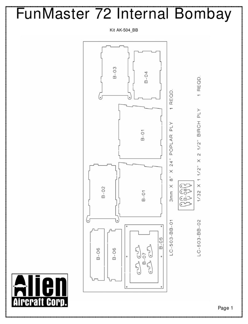
1...Thefirstthingthatyouneedtodoistoidentifyandmarkthepartnumbersonthelasercutpartsusingthedrawingsonthefollowingpagesasaguide.
2...It ispossiblethat severalofthelasercutpartsmaynotbecompletelycutthrough.IfthisisthecaseyoucanfreethepartfromthesheetquicklyusinganX-actoknife.
3...Theslightdiscolorationontheedgesofthelasercut partsmayberemovedbylightlysandingtheedgeswith400 grit sandpaper.
KitContents:
Yourkit containsthefollowing parts.Pleasecheckyourkitforanymissingordamagedpartsbeforestartingconstruction.
WoodBag:
Qty.. . .....Name...... . . ...... . . ......Description
2.. . . .....LC-307-01.. . . ...... . . ......1/16”X4”X24”LaserCutBalsa
2... . . .....LC-307-02.. . . ...... . . ......1/16”X4”X24”LaserCutBalsa
1... . . .....LC-307-03.. . . ...... . . ......3/32”X4”X24”LaserCutBalsa
1.. . . .....LC-307-04.. . . ...... . . ......3/32”X4”X24”LaserCutBalsa
1... . . .....LC-307-05.. . . ...... . . ......1/8”X4”X24”LaserCutBalsa
1.. . . .....LC-307-06.. . . ...... . . ......1/8”X4”X24”LaserCutBalsa
1.. . . .....LC-307-07.. . . ...... . . ......1/8”X4”X24”LaserCutBalsa
1... . . .....LC-307-08.. . . ...... . . ......1/8”X4”X24”LaserCutBalsa
1.. . . .....LC-307-09.. . . ...... . . ......1/8”X4”X24”LaserCutBalsa
1.. . . .....LC-307-10.. . . ...... . . ......1/8”X4”X24”LaserCutBalsa
1... . . .....LC-307-11... . . ...... . . ......3mm X4”X24”” LaserCutPoplarPly
1.. . . .....LC-307-12.. . . ...... . . ......3mm X4”X24”” LaserCutPoplarPly
1.. . . .....LC-307-13.. . . ...... . . ......1/16”X3”X12”LaserCutBirchPly
1... . . .....LC-307-14.. . . ...... . . ......1/32”X3”X12”LaserCutBirchPly
1... . . .....LC-307-15.. . . ...... . . ......3/32”X4”X12”LaserCutBalsa
3.. . . .....Wing Sheet.. . . ...... . . ......1/16”X3”X12”Balsa
1... . . .....K-307PLAN A
1... . . .....K-307PLAN B
6... . . .....MainWing Spars...... . . ......3/32”X1/4”X24”Balsa
2... . . .....Wing Leading Edges... . . ......1/4”sq. X24”Balsa
13.. . . .....FuselageStringers..... . . ......1/8”sq. X36”Balsa
8... . . .....StringerSpars. . ...... . . ......3/32”sq.X24”Balsa
1... . . .....Pushrod Supports&F-12Brace..3/32”X3/16”X12”Balsa
Hardware Bag
Qty.. . .....Name...... . . ...... . . ......Description
5... . . .....Blind Nuts... . . ...... . . ......4-40BlindNuts
1.. . . .....Elevator Joiner. ...... . . ......1/8”x31/2”BirchDowel
4... . . .....ControlHorn. . . ...... . . ......ControlHorns
5... . . .....C/AHinges.. . . ...... . . ......Hinges
16.. . . .....AileronServo &L/GScrews .....#2X1/2”SheetMetalScrews
1... . . .....Wing Attach. . . ...... . . ......4-40X2”MachineScrew
1... . . .....TailwheelReinforcement. . ......1”X11/2”Nylon Tape
1... . . .....TailWheelWire...... . . ......1/16”x3”TailWheelWire
2... . . .....Landing GearBlocks... . . ......3/8”Hardwood Blocks
1... . . .....Wing Dowel. . . ...... . . ......3/16”X11/2”Dowel
1... . . .....TailwheelRetainer.... . . ......Nylon WheelRetainer
1... . . .....Landing GearDoorStandoff.....3/16”X3/16”X3”Balsa
1... . . .....Wing AttachBlock.... . . ......3/8”sq. X1”DrilledHardwood Block
Page2
KitContents:
Yourkit containsthefollowing parts.Pleasecheckyourkitforanymissingordamagedpartsbeforestartingconstruction.
Misc.LooseParts
Qty.. . .....Name...... . . ...... . . ......Description
2... . . .....K-307DecalSheet
1... . . .....K-307PlasticCanopy
1... . . .....K-307RightLanding Gear
1... . . .....K-307LeftLanding Gear
AdditionalItemsRequired(NotIncludedinKit)
Note:Thesearepartsthatwehaveusedand arefamiliarwith.Therearemany otherbrandsavailableand you maysubstituteother
itemsthatyou aremorecomfortablewithor haveon hand.
Qty.. . .....Name...... . . ...... . . ......Description
1... . . .....Motor...... . . ...... . . ......HimaxHC2816-0890 BrushlessMotor(AlienAircraftP/N:AE-035)
1... . . .....SpeedControl. . ...... . . ......CastleCreation Thunderbird-18ElectronicSpeedControl
(AlienAircraftP/N:AE-019) withconnectorsmatchingmotor&battery
1... . . .....Battery Connector..... . . ......MaleDeansUltraconnector (AlienAircraftP/N:AE-027)
1... . . .....HeatShrinkTube..... . . ......3/16”Heat Shrink Tube(AlienAircraftP/N:AE-029)
2... . . .....TailPushrods. . ...... . . ......DubroMicro Pushrod Set(AlienAircraftP/N:AH-001)
2... . . .....AileronPushrods...... . . ......AlienAircraft5”pushrod set(AlienAircraftP/N:AH-012)
1... . . .....Propeller.... . . ...... . . ......APC9X3.8SF Propeller(AlienAircraftP/N:AE-036)
2... . . .....Velcro...... . . ...... . . ......6"Velcro (AlienAircraftP/N:AE-012)
4... . . .....2816-0890Motor MountScrews..4-40X1/2”MachineScrews (AlienAircraftP/N:AE-037)
2... . . .....MainWheels. . . ...... . . ......DuBro21/2”DiamondLiteWheels(DuBro #250DL)
1... . . .....TailWheel... . . ...... . . ......DuBro1”MiniLiteWheel (DuBro #100MW)
1... . . .....Spinner..... . . ...... . . ......GreatPlanesAluminumE-Spinner2-1/4"(P/N:GPMQ4727 )
1... . . .....SpinnerAdapter...... . . ......GreatPlanesAluminumE-Spinner1/4"-28 Adapter(P/N:GPMQ4731)
1... . . .....Prop Adapter. . . ...... . . ......GreatPlanesColletProp Adapter4.0mmto1/4x28 (P/N:GPMQ4965 )
2... . . .....WheelCollars. . ...... . . ......DuBro3/32”WheelCollars(P/N:#138)
1... . . .....Battery..... . . ...... . . ......3Cell 1250Mahto1800mAh20C Lipo Battery
1... . . .....Covering Material..... . . ......LightWeightCovering MaterialPlusTrimColors
1... . . .....Radio...... . . ...... . . ......4ChannelRadiowith4microservos&Receiver
withone“Y”connector andservo extensionsifrequired.
Page3

Page4

Page5

BuildingInstructions:
GeneralNote:Covertheplanswithwaxpaperbeforeassembling yourmodeltopreventthepartsfromsticking to
theplan.
BuildingtheTail Surfaces:
1...GlueR-1and R-2together.BevelthefrontedgeofR-3asshown
on theplan, and sand theotheredgesround.
Markthehingelocations and cutthehingeslots inR-2and R-3.
Temporarilyinstall thehingeswithoutglue.Sand thefrontedgeof
R-1&R-2round.Leavetheotheredgessquare.
2...Bend thetail wheelwirefromthe1/16”x3”musicwire.Leavethe
axleend long.Itwillbetrimmedtolengthwhenthetailwheelis
installedlater.
3...Drillaholeintherudder(R-3)forthetailwheelwireattheloca-
tion shownon theplan. Cutagrooveinthefrontoftherudderforthe
tailwheelwiretofit intosothatit isflushwiththefrontoftherudder.
Gluethetail wheelwireintotherudder.
Tightlywrapand gluethe1”nylon tapereinforcementintoposition
around thetail wheelwire.Trim any excessand sand thetapesmooth.
4...Jointheelevators(S-2)using the1/8”x31/2”dowel.Usethesta-
bilizeras aguide.BevelthefrontedgeoftheS-2’s asshownon the
plan,and sand theotheredgesround.
Sand thefrontand ends ofthestabilizer(S-1)round.Leavetheback
edgesquare.
Markthehingelocations and cutthehingeslots.Temporarilyinstall
thehingeswithoutglue.
Page6

BuildingtheFuselage:
5...GlueF-1Land F-1RtothefrontofthetwoF-2’s overthedrawing on theplan.TheF-1L/F-2will belonger
thantheF-1R/F-2.
6...PinF-3and F-4intoposition on thefuselageplanas shownand gluethemtogether.
7...PinF-5,F-6and F-7intoposition on thefuselageplanasshown. GlueF-5toF-4and F-6.
8...CrackthetwoF-13’s atthedashedlinesand anglethetop
section up.UsepartFXtosettheproperangleand apply
gluetotheparttolocktheanglein.Besuretomakeone
leftand oneright.
9...CrackthetwoF-15’s atthedashedlinesand anglethe
bottomsection up.UsepartFXtosettheproperangleand
applygluetotheparttolocktheanglein.Besuretomake
oneleftand oneright.
Page7

10...Place formerF-9intoposition on F-3and F-7.Thetop edge
shouldangleforwardfortherightthrustforthemotor.UsepartFYto
holdtheproperanglewhileyou glueF-9intoposition.
PlaceformerF-8intoposition on F-3and F-7.Thetop edgeshould
angleforwardfortherightthrustforthemotor.UsepartFYtohold
theproperanglewhileyou glueF-8intoposition.
11...Place formers F-10 thruF-18 intoposition.Theseformersshouldbe90 degreestothebuilding board.When
properlypositioned,gluetheminplace.PinthebottomofF-12 and F-13 securelyinposition on theplan.Pinfor-
merF-14 securelytotheplan. Lineup thenotchesforF-1/F-2withtheplantobesurethatyou do notglueany of
theformerson upsidedown.
12...Place F-1L/F-2intoposition on theformers.Working fromthebacktothefront,glueF-1L/F-2toF-5and then
totheformers.FormersF-14,F-13 and F-12 sit alittlelowsoyou will havetopressF-1L/F-2intothenotchesand
holdit inposition whilethegluedries.UsepartFYtomakesurethatyou do notchangetheangleofF-8and F-9.
Makesureall oftheotherformersare90 degreestothebuilding board.
13..Trim ataperon thetwoF-20’sas shown.Theangle
extendsfromthemarkedlineand taperstoapointatthe
backedge.
Page8

14...Position theleftF-20 intoposition on thefuselageasshownwith
thetaperdown. Thefrontend fitsinthenotchand isflushwiththe
frontofF-18. Thebottomend sitstightagainstF-1L/F-2and theback
end sitson top ofF-5. Whenproperlypositioned,glueF-20 inplace.
15...Place thetwo1/8”sq. full lengthstringers intoposition on thefuselagedirectlyaboveand belowF-1L/F-2.The
upperstringerendsinthenotchinF-20.Taperthebackend ofthelowerstringerasyou didF-20.Whenproperly
positioned,gluethestringersinplace.Leavethefrontendslong,extending pastF-8.Theywill trimmedflushwith
theformerlater.
16...MoistenbothsidesofthefronthalfofF-19 withanammoniabasedglasscleanersuchasWindexand allowit to
sit forseveralminutes. Place it intoposition on thefuselage.Working fromthebacktothefront,glueF-19 securely
totheformers.Bend /roll thefrontend downsoit fitstightinthenotchesinF-12 and F-11.
17...Cut, fit and gluethethree lowerfront1/8”
sq.stringersintoposition asshown.Leavethe
frontendslong,extending pastF-8.Theywill
trimmedflushwiththeformerlater.
Page9

18...Cut, fit and gluethetwoupperfront1/8”
sq.stringersintoposition asshown.Leave
thefrontendslong,extending pastF-8.
Theywill trimmedflushwiththeformer
later.
19...Cut, fit and gluethefivelowerrear1/8”sq. stringers intoposition asshown.Thefirstand thirdstringerfrom
thebottomend againstthefrontface ofF-17.Theothersextend backtoF-5.Taperthebackendsasyou didF-20.
Leavethefrontendslong.
20...Donotgluethetop rearstringersintoplace until later.Removethefuselagefromtheplan.
21...GlueF-8and F-9totherightsideofthefuselage. Makesurethat
theymatchtheangleoftheformerson theleftside. You canusea
small flatpiece ofscrapwood tohelpalign theformersand makesure
thattheyareflushwiththeoppositeside.
Page10

22...Place formers F-10 thruF-18 intoposition.Theseformers shouldmatchthe90 degree angleoftheformers on
theoppositeside. Whenproperlypositioned,gluetheminplace.Becarefultonotglueany formersinupsidedown.
23...Place F-1R/F-2intoposition on theformers.Working fromthebacktothefront,glueF-1R/F-2toF-5and then
totheformers.Makesurethatyou do notchangetheangleofF-8and F-9.
24...MoistenbothsidesofthefronthalfofF-19 withanammoniabasedglasscleanersuchasWindexand allowit to
sit forseveralminutes. Place it intoposition on thefuselage.Working fromthebacktothefront,glueF-19 securely
totheformers.Bend /roll thefrontend downsoit fitstightinthenotchesinF-12 and F-11.
Glueapieceof3/32”x3/16”balsaacrossthebottomfrontofFormerF-12.
25...Position F-20 intoposition on thefuselageasshown. The
frontend fitsinthenotchand is flushwiththefrontofF-18.
Thebottomend sitstightagainstF-1R/F-2and thebackend sits
on top ofF-5.Whenproperlypositioned,glueF-20 inplace.
Page11

26...Press four4-40 blind nuts intoF-21.Useasmall drop ofthin
C/Atosecuretheminplace.
27...GlueF-21,bothF-22 and bothF-23 securelytogetherasshownto
makethemotormountassembly.Useseveralsmall applicationsof
thinC/Aglueuntil itstopssoaking intotheplywood.
28...Position themotormountassemblyinplace on thefrontofF-9.
Makesurethatit iscompletelyseatedand glueinplace withseveral
applicationsofthinC/Aglueuntil it stops soaking intotheplywood.
29...CutthebottomsawayfromFormers F-13 and F-14 asshown.
30...Place F-25 on thefrontofformerF-11.Align theholes.When
properlypositioned,glueF-25 totheformer.
Page12

31...Place partF-24 intoposition asshown, centeredleftand right. Itshouldreston thebottomoftheF-1/F-2’son
eachsideand formers F-13 and F-14 shouldbecenteredintheslots.Whenproperlypositioned,glueF-24 tothe
F-1/F-2’s on eachside.
32...Fit and gluethe1/8”sq. stringers intoplace asyou didtheoppositeside.
33...Trim F-3/F4frombetweenformers F-13 and F-15.Trimthestringersand sand flushwiththeformers.
34...Makethetailfairingsby gluing partsF-26 thruF-31 together
asshown.Besurethatyou makeonelefthand and oneright
hand
Page13

35...Gluethetail fairingstothebackofthefuselage
againstF-4and F-18.Thereshouldbea1/8”gap
betweenthefairingsand theF-20’s.Slidethestabilizer
inposition as atemporaryspacer.Becarefultonot
gluethestabilizer.
36...Place F-32 on thefuselage.Thefrontlegsfit inthenotch-
esinformerF-13.Itshouldreston top offormerF-14 and
tightlyagainstthefrontofF-15.Trim anangleinthenotches
inF-13 asrequiredtoachievetheproperfit.Makesurethe
frontand backendsarecenteredand thatthebackend is level
and nottwisted.Whenproperlypositioned, glueF-32 tothe
formers.
37...Fit and gluethetop rearstringersintoposition.ThelowerstringerendsagainsttherearfaceofF-14, touching
thebottomofF-32,and flushwiththeoutsideedgeofF-14.
38...GluethetwoF-33’stotheinsideofpartsF-19.
Page14

39...Position F-34 securelyinthenotchedintheF-33’s. Glueit tothe
F-33’s,theF-19.sand F-15.
40...GluethetwoF-35’s,F-36, twoF-37’sand F-38 togetheras
shown.
41...Trim and sand any stringersflushwiththefrontofF-8. Gluethe
noseassemblytothefrontofthefuselage.
42...Sand thenoseassemblyasshown.
Page15

43...Sand thefuselagesmoothall over.Blend and shapethecanopy rails(F-32)and thetailfairings.
44...Testfit themotortothemountwith4-40 x1/2”screws. The
motorwireswill passthrough oneoftheholesinthebottomofF-9.
45...Install theprop adapter, spinnerbackplate,propeller,washerand
prop nut.Screwtheprop adapterontotheprop shaft.
46...Install thespinnerwiththescrewthrough thefrontintothespinner
adapter.Makesurethatthemotorspinsfreely. Thereshouldbea
1/16”to3/32”gapbetweenthespinnerbackplateand thefrontofthe
fuselage. Sand thefrontofthefuselageifrequiredtoachievetheprop-
ergap.Nowremovethespinner,propellerand motorfromthemodel.
Page16

BuildingtheBellyScoop:
47...PinP-1and P-2totheplan.
48...GlueformersP-3,P-4and P-5inplace.Theshouldbe90 degrees
tothebuilding board.
49...GluepartP-6intoposition.
50...Gluethe1/8”sq. stringers intoposition.
51...GlueformersP-3,P-4and P-5intoposition on theoppositeside.
Makesurethattheyarestraightand alignedwiththeformerson the
oppositeside.
Page17

52...GluepartP-6intoposition on thissideofthescoop.
53...Gluethe1/8”sq. stringers intoposition.
54...GlueP-7and P-8togetherand thengluethemtothefrontofthe
scoop.
55...Sand thescoop smoothall overand shapethefrontend.
Page18

56...GluethetwoP-10’stooneend ofP-9.
57...GlueP-9/P-10 intoposition oneonesideofP-1and P-2asshown
hereand on theplan.Itdoesn’tmatterwhichsideyou choose.
Sand theP-10’sflushwiththescoop.
BuildingtheWing:
Note:Coverthewing planwithwaxpapertopreventthepartsfromsticking totheplan.
BuildingtheLeftWing:
58...Cutoneofthe3/32”x1/4”x24”balsaspars intotwo12”lengths.
Glueeachofthese12”pieces tooneofthe3/32”x1/4”x24”balsa
sparsas shownon theplan.Thismakestheupperand lowermain
spars.
59...Pinonemainsparassemblytotheplanwiththe12”section on thetop.Align theend ofthe12”doublerwith
themarkon theplan.Theinboardend will extend pasttheW-1rib.Theoutboardend willextend pasttheW-9tip
rib. Note:Thedoublesection istheinboardend.
Page19

60...GluetheW-1A,W-4Aand W-5Adoublerstothe
frontofribs W-1,W-4and W-5. Besuretomakealeft
and righthand assemblyofeachribasshown.
61...Pinand glueribW-2intoposition on thebottomspar90 degrees
tothebuilding board.
62...Place shearweb“A”intoposition and gluetothefrontface ofthe
spar. Thesmall “X”on theshearwebmarksthetop outboardcorner.
63...GlueribW-1intoposition.Itshouldbetightagainstshearweb
“A”and thetop edgewill angleslightlytowardthewing tip.
64...Pinand glueribsW-3thruW-9intoposition
on thebottomspar90 degreestothebuilding
board.
Note:TheW-4Aand W-5Adoublersshould
faceeachotherwiththelanding gearmount
betweenthemasshownon theplan.
Page20
Table of contents
Other Alien Aircraft Corp Toy manuals

Alien Aircraft Corp
Alien Aircraft Corp FunMaster 72 K-504 User manual

Alien Aircraft Corp
Alien Aircraft Corp K-308 User manual

Alien Aircraft Corp
Alien Aircraft Corp FunMaster 72 User manual

Alien Aircraft Corp
Alien Aircraft Corp K-501 User manual

Alien Aircraft Corp
Alien Aircraft Corp Taylorcraft 72 User manual

Alien Aircraft Corp
Alien Aircraft Corp ArrowMaster 55 User manual

Alien Aircraft Corp
Alien Aircraft Corp Hornet K-107 User manual

Alien Aircraft Corp
Alien Aircraft Corp C-310-B User manual