Big Chill BCCH 18 Series User manual

197300 Rev 1
USER MANUAL: INSTALLATION AND USE & CARE
Models: BCCH**18*, BCPH4818*, BCRH**18*

Please take a few moments now to fill in the information below for your future reference in the event you
require parts or service.
DATE OF PURCHASE:
DEALER’S NAME:
DEALER’S ADDRESS:
DATE OF INSTALLATION:
INSTALLER’S NAME:
INSTALLER’S ADDRESS:
MODEL NUMBER:
SERIAL NUMBER:
2 (877) 842-3269

Table of Contents
INSTALLATION INSTRUCTIONS:
5 Handling and Unpacking
7 Installation of Ducting & Electrical Specifications
8 Removing Liner from Hood Shell
9 Installing the Blowers
10 Mounting Hood Shell to Wall and Reinstalling Liner
USE AND CARE INSTRUCTIONS:
12 Operating the Push Button Controls
13 Cleaning Instructions
15 Warranty
bigchill.com 3

1. This appliance was designed for ease of installation and operation. However, we recommend that you read all
sections of this manual before you begin installation.
2. Do not remove permanently affixed labels, warnings or data plates from your appliance. This may void the
manufacturer’s warranty and/or hinder effective servicing and maintenance. These instructions are to remain with
the appliance and the consumer is to retain them for future reference.
3. Please observe all local and national build codes and ordinances. If no local codes are applicable, please follow all
wiring requirements in accordance with the National Electrical Code.
4. Please check your local codes for any make-up air requirements.
5. This hood is for residential use only and is not designed for installation over a commercial product.
To reduce the risk of fire, electric shock or injury observe the following:
•Use this unit in the manner intended by the manufacturer.
•Before cleaning or servicing unit, turn power off to the unit at the service panel.
•Installation work and electrical work must be performed by qualified individuals in accordance with all applicable
codes and standards, including fire-rated construction.
•Do not damage any existing electrical or hidden utilities when drilling, cutting and/or removing a wall, ceiling or floor.
•Sufficient air is required to properly exhaust gases through the flue of natural and liquid propane fueled cooking
equipment to avoid any backdrafts.
•Use only metal ductwork. Do not use flexible or corrugated duct.
•Never vent ducted exhaust air into another room or garage. Ducted exhaust air must vent outdoors.
INSTALLATION INSTRUCTIONS
4 (877) 842-3269
IMPORTANT
WARNING
!

•If a fire should occur, do not turn on hood to evacuate smoke. Turn off hood.
•Do not use to exhaust hazardous, flammable or explosive materials.
•Clean baffle filters often, since accumulated grease can be a fire hazard and affect the performance of your
ventilation hood.
Handling:
•Do not remove the hood from original packaging until you are ready to install.
•Remove all watches, belt buckles, jewelry, rings and any clothing with metal buttons or snaps to prevent damage to
the hood.
•When you begin the installation process, remove the hood from its original packaging and place on a clean, non-
abrasive blanket.
•When removing the hood from the carton, locate the filters since they could be packed separately.
INSTALLATION INSTRUCTIONS
Unpacking:
•Ensure the container is upright. If the container is not upright, major damage can occur to your appliance.
•Move the container as close to its installation location as possible. This will reduce moving and handling your
appliance once it is out of its shipping container.
WARNING
!
bigchill.com 5

INSTALLATION INSTRUCTIONS
To reduce the risk of fire and electric shock, install this ventilation unit only with manufacturer approved blowers. Your
ventilation hood is designed to work specifically with the integral blower requested.
In selecting the proper height to mount the hood, take
into consideration the stature of the person or persons
who will be cooking. A minimum height of 30” off the
cooking surface to a maximum height of 36” will suit
most users.
The bottom of the hood should be 30” minimum to 36”
maximum above the countertop. This would typically
result in the bottom of the hood being 66” – 72” above
the floor. The bottom of the hood should never be more
than 72” above the floor or more than 36” above the
countertop. These dimensions provide safe and
efficient operation of the hood.
Site Preparation: Selecting the Appropriate Height for Installation
HEIGHT FROM FLOOR
68"(MIN)-72"(MAX)
167.6cm-182.9cm
COUNTERTOP
HEIGHT ABOVE COUNTERTOP
30"(MIN)-36"(MAX)
76.2CM-91.4CM
Height above Countertop
30” min – 36” max
762mm –914mm
Height from Floor
66” min – 72” max
1676mm –1829mm
Countertop
36” (914mm) typical
CAUTION
!
6 (877) 842-3269
Installation of Ducting for Proper Operation:
Proper installation of ducting is extremely important for optimal performance of your ventilation system. It is a basic
requirement that the kitchen is provided with an air intake to ensure good air circulation and, therefore, proper operation
of the hood. Without this incoming air, a depression could form that would reduce the efficiency of the ventilation
system.
•Be sure to follow local building codes for electrical, structural, general HVAC, and make-up air requirements.
•If duct shape is changed along path (round to square), the cross-sectional area must not be reduced.
•The duct run should be kept under 30 feet for a straight run. For every 90 degree turn in the duct run, subtract 5 feet
from the total (25’ for a duct run with 1 elbow, 20’ for a duct run with 2 elbows, and so on). Longer runs will result in
decreased performance and possible noise concerns.
•Avoid sharp-angled turns. Use smooth gradual turns, such as adjustable elbows or 45-degree angled turns.
•Airflow must not be restricted at the end of the duct run.
•A backflow damper is not provided. It should be sourced locally and sized for your specific duct work.
•Duct should terminate to an outdoor space above the roof line or outside a side wall of the building. Do not
terminate the run into an attic or chimney.
INSTALLATION INSTRUCTIONS
Electrical Specifications:
This hood is designed to be plugged into a dedicated 3-
prong ANSI or Non-GFCI outlet –120Volt, 60Hz, 1Ph,
10amp. min.
Outlet location: Confirm with local building codes for
accessibility requirements. The outlet may be
positioned above the hood shell to provide access for
the cord along the duct exhaust. Ensure the outlet will
not be obstructed by the duct work. The power cord will
extend up to 36” from the top of the liner.
Depending on specific installation conditions,
access to the outlet may be difficult.
If an appropriate outlet is not available or is inconvenient
due to the specific installation, the power cord may be
removed at the liner’s junction box, and the hood may
be direct wired to a dedicated non-GFCI 120V, 60Hz,
1Ph, 10amp min circuit. Use 14-2 MC shielded cable or
equivalent, unless directed otherwise by local building
codes.
3-prong cord attached
3-prong cord removed
for direct wire
To reduce the risk of fire, electric shock or injury, observe the following:
•Use only metal ductwork. Do not use flexible or corrugated duct.
WARNING
!
bigchill.com 7

INSTALLATION INSTRUCTIONS
Figure E: Remove Mounting Screws
Remove Philips screws in front and back
of liner that attach it to the outer shell.
Screws are located behind scalloped
detail in flange front and back.
Step 2: Remove ventilation hood liner from outer shell. (Figures A through F) –save all components and fasteners as
they will be used to reinstall the liner after the hood shell is mounted to the wall.
Figure A:
Remove Baffle Filters
Pull filter(s) towards front of hood and tilt
rear of filter down to remove.
Figure C:
Remove Inner Shield (only on models that
require blower installation or discharge
reorientation)
Remove Philips screws (front and back)
attaching shield to ventilation hood liner.
Figure D:
Remove Control Panel
Remove screws attaching panel to
ventilation hood liner. Disconnect control
and light harnesses.
Step 1: Read all instructions thoroughly before beginning installation. Please review all steps before beginning –
for some installations, the order of assembly may be altered.
Figure F: Remove Liner from Shell
Carefully slide liner out of outer shell.
Remove any protective film from exterior
of liner and baffle filters.
8 (877) 842-3269
Figure B:
Remove Rear Filter Holder
Turn wing fastener(s) ¼ turn to unlock.

Step 3: Install / Set discharge orientation for blower (if not already configured as needed for your application).
Duct connection detail: 6” round at discharge. Recommended duct size: 6” min., 8” max.
Figure A:
Set Discharge Direction, Attach Blower
Unscrew blower plate and set to top or rear
discharge if not already set correctly. Screw
blower to plate with included hardware
Figure B:
Connect Plate Internally
Re-install all mounting screws inside of liner.
Figure C:
Connect Plate Externally
Re-install all mounting screws outside of liner.
Figure D:
Connect Power Supply
Plug 6-pin connector from one of the control harnesses
to blower. Unused harness may be tied securely to other
harness to prevent vibration
INSTALLATION INSTRUCTIONS
bigchill.com 9

5. Hardware is not provided with this unit to secure it to the wall. Local building codes take precedence (where
applicable). Otherwise, use #12 screws or larger lag screws with a length such that at least 1” of thread is embedded
into a structural member (i.e., wood stud or blocking) behind the mounting surface. Be sure to consider the
thickness of wallboard (drywall, tile, etc.) when determining appropriate length of fastener. A minimum of 2 screws
in the upper portion of the hood, and 2 screws in the lower portion of the hood should be used to ensure the hood is
attached securely to the wall.
a. Additional screws should be used for wider hoods:
• 36” wide hoods and smaller:
2 screws upper portion, 2 screws lower portion.
• 48” wide hoods:
3 screws upper portion, 3 screws lower portion.
INSTALLATION INSTRUCTIONS
1. The bottom of the hood should be 30” minimum to 36”
maximum above the countertop for efficient operation. The
hood should be centered over the cooking surface.
2. Measure and mark carefully and locate framing behind the
wallboard using a stud finder. Add structural blocking
where necessary to ensure hood is attached to the wall
securely.
3. In the back of some model’s hood shell, there are only a
few small oblong slots provided for screws to pass through.
If necessary, it is acceptable to drill new holes in the sheet
metal back of the hood shell to align with framing behind
wallboard.
4. Depending on fastener selected, pre-drilling may be
necessary to avoid splitting the framing or blocking.
HEIGHT FROM FLOOR
68"(MIN)-72"(MAX)
167.6cm-182.9cm
COUNTERTOP
HEIGHT ABOVE COUNTERTOP
30"(MIN)-36"(MAX)
76.2CM-91.4CM
Height above Countertop
30” min – 36” max
762mm –914mm
Height from Floor
66” min – 72” max
1676mm –1829mm
Countertop
36” (914mm) typical
48”
Step 4. Mount the Outer Hood Shell to the Wall
<=36”
structural members / studs
optional
blocking
10 (877) 842-3269

INSTALLATION INSTRUCTIONS
Step 6. Connect Ducting to Ventilation Hood
Install ducting around starter collar on top or rear of hood and seal according to building code regulations. Be sure to
include a back draft damper in the duct work to prevent drafts.
Step 5. Re-install Liner into Outer Shell
Figure A:
Lift Liner into Shell
Carefully re-install liner to
avoid scratches or damage.
Ensure cables are dressed
carefully to avoid pinching.
Figure B:
Attach Liner to Shell
Re-install with all the screws
removed previously that held
the liner to the hood shell
during shipment.
Figure C:
Re-install Control Panel,
Screen and Filters
Attach button control harness
and light wires. Insert control
panel’s tabs into slots in front of
liner. Drive screws attaching
panel to liner.
Install screen and filters.
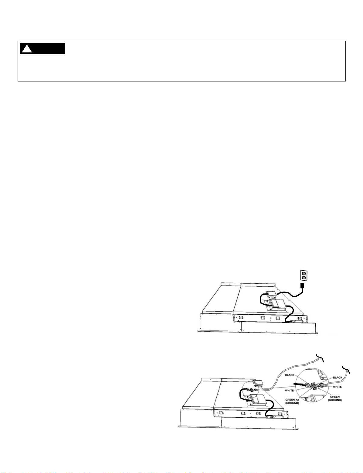
1. Connect Electrical Supply (see Electrical Specifications
on page 7)
a. Route power cord from liner to outlet location and
plug in.
b. If alternate direct wire method is desired, remove
power cord from junction box and connect power
supply cable directly in its place being sure to
match wire colors appropriately.
2. Complete liner
installation by inserting
into hood shell (A),
driving screws (B), and
reinstalling covers and
filters removed
previously (C).
3. If ductwork is already in
position, be sure to align
properly as liner is
inserted.
a. to outlet
b. power cord
junction box
Turn off power at the service panel prior to wiring the blower.
WARNING
!
bigchill.com 11

USE & CARE INSTRUCTIONS
Control Panel
A B C D E F
Blower
Controls Light
Controls
Timer
Blower Controls:
A–Blower power on, power off, low speed
B –Blower middle speed
C–Blower high speed
D –Blower Boost function*
*After 7 minutes of operation, the blower will
automatically move to high speed (C). The Boost
icon will blink while active.
Additional Controls:
E –Timer
Pressing button during blower operation will
cause blower to run for 15 minutes at its current
speed, and then automatically shut off. The timer
icon will blink while active.
If timer icon is blinking when the blower is not
running, this indicates the filters are due to be
cleaned. Clean the filters as directed, then press
and hold for 3 seconds to reset the filter clean
reminder.
F –Light On/Off plus Dimming Feature
Press and release to turn light on or off. Press
and hold to adjust light intensity. Release when
light reaches desired intensity. Selected intensity
will stay in controller memory until changed.
12 (877) 842-3269

The function of the baffle filters is the absorption of grease particles that form during cooking. Do not operate
ventilation hood without filters in hood. Baffle filters should be examined periodically to assure that the
surfaces and parts are clean.
IMPORTANT
USE & CARE INSTRUCTIONS
Baffle Filters
Removing Baffle Filters:
•Hold both handles located on the filter.
•Pull towards front of hood to depress spring.
•Pull back of filter down and away from hood.
Removing Rear Filter Holder:
Filter holder is located at base of baffle filters in rear of hood (Figure 1).
•Turn wing fastener(s) ¼ turn to release.
•Pull filter holder towards front of hood and remove.
Removing Inner Shield:
Inner shield is located behind baffle filters (Figure 2).
•Remove screws attaching shield to ventilation hood liner.
Figure 1
Figure 2
Cleaning Baffle Filters and Rear Filter Holder:
Baffle filters should be cleaned regularly to prevent grease droplets from forming. The baffle filters are
dishwasher safe or can be cleaned in a sink with warm, soapy water. Do not use caustic detergent to clean the
filters. Abrasive cleaners may harm or damage the finish. Do not disassemble the baffle filter. Disassembly
will void the warranty.
The rear filter holder should be cleaned with dish soap and warm water. Depending on the size of the hood, it
may be cumbersome to wash the filter holder in a kitchen sink. Spraying with a grease cutting cleaner for
kitchen use and rinsing with a garden hose in an open area may be the easiest way to clean. Be sure to rinse
thoroughly and allow to dry completely before reinstalling.
Your hood must be kept clean and maintained properly
•Do not use abrasive cleaners, steel wool pads, or abrasive cloths.
•Do not allow grease to accumulate. For best results, wipe the canopy down with a soft cloth and warm,
soapy water.
•The cleaning of the outside of the hood depends on the material used as a decorative exterior. See
following details for hood specific material cleaning instructions.
•Do not use abrasive or aggressive chemicals to clean the interior or exterior of the hood.
Cleaning Interior and Exterior:
bigchill.com 13

USE & CARE INSTRUCTIONS
Cleaning the Interior
Clean the interior of the hood using a soft cloth and warm soapy water or denatured alcohol as needed. Do not
clean the electrical parts or blower with liquids or solvents. Allow to dry thoroughly before restoring power.
Cleaning the Exterior
It is important to follow the direction of the metal grain with the cloth. Do not use chemical solvents, aggressive,
grainy or abrasive products or similar products that could damage the surface of the hood. Test in an
inconspicuous location if you are concerned about a particular cleaner. For various finishes, see details below.
•Painted with Gloss Finish
Clean with a soft cloth and quality glass cleaner or warm soapy water. Follow all label instructions.
•Brushed or Polished Stainless Steel (Strapping, Utensil Rails –some models)
Clean with a soft cloth and quality stainless steel cleaner or warm soapy water. Follow all label
instructions. Do not polish across the grain or in circles.
•Brushed Brass, Brushed Copper (Strapping, Utensil Rails –some models)
Clean with a microfiber cloth using Endust, Pledge (or similar cleaner) or warm soapy water. Follow all
label instructions.
For cleaning the hood, it is recommended to use a soft cloth and a solution of warm soapy water. It is important
that the soap does not contain granules that could scratch the surface. Follow the direction of the metal grain with
the cloth. The cloth must have no buttons or fasteners that could scratch the surface. Do not use chemical
solvents, aggressive, grainy or abrasive products or similar products that could damage the surface of the hood.
Test in an inconspicuous location if you are concerned about a particular cleaner.
Turn off power at the service panel prior to cleaning the hood.
WARNING
!
14 (877) 842-3269

bigchill.com 15
Big Chill Warranty
Big Chill, Inc. warrants your Big Chill appliance (“product”)
purchased in the U.S. and Canada and installed in residential
properties for normal residential use.
What Is Covered
Subject to the specific conditions and limitations below, this
warranty covers parts and/or labor necessary to repair or replace
any part of the product that contains defects in materials and
workmanship.
One-Year Warranty
For one (1) year from the date of installation, this warranty covers
all parts and labor necessary to repair or replace any part on the
product except for the Cosmetic Warranty below.
Cosmetic Warranty
Big Chill offers a seven-day cosmetic warranty from the date of
delivery on all deliveries. The Owner must report cosmetic
imperfections within this seven-day period, supported by pictures
and note “subject to inspection” at the time of delivery.
Limitations of Coverage
•The replacement of a part under this warranty does not extend
the warranty period.
•Warranty service outside normal business hours and in areas
beyond 50 miles one way from an authorized service provider.
The owner will be responsible for any and all costs associated
with additional mileage, non-standard service or overtime, and
special equipment required to remove the product so service
may be performed.
This warranty is null and void:
•If the product is removed from where it was originally installed.
•If the original factory installed serial number is altered or
removed from the product.
What Is Not Covered
This warranty does not cover, and specifically excludes:
•Product installed or used in any commercial or other non-
residential property such as, but not limited to, day care
facilities, fire stations, hotels, nursing homes, rentals, vacation
properties, etc.
•Installation related issues including improper badge placement
or installation inconsistent with the product
specifications/installation instructions.
•Damage or repairs caused by alterations or modifications,
abuse, misuse, neglect, or improper installation, mounting,
handling, operation, maintenance, or storage.
•Normal adjustments after installation and setup.
•Normal wear, care, and maintenance of the product as
described in the use and care manual.
•Service calls to educate the customer on the proper use and care
of the product.
•Consumable parts such as water filters.
•Damage or repairs caused by unauthorized service or repairs,
including unauthorized adjustments or calibrations performed
on the product.
•Accidental or intentional damage.
•Damage or repairs as a result of natural disasters, fires, floods,
earthquakes, winds, lightning, corrosive atmosphere, loss of
electrical power to the product for any reason, or other
conditions beyond Big Chill’s control.
•Damage or repairs caused by alteration for outdoor use.
•Damage or repairs caused by the use of harsh chemicals or
cleaning products improperly applied.
•Liability or responsibility for damage to surrounding property
including cabinetry, floors, ceilings, etc.
•Consequential or incidental damage, including but not limited to
food or medicine loss, restaurant meals, etc.
The terms of this warranty provide for repair of the product only. If
the product cannot be repaired, Big Chill, at its sole discretion, will
determine whether to exchange the product.
Please see the Arbitration Clause and Related Provisions, which affect
your legal rights. The Arbitration Clause is available at
www.bigchill.com.
This warranty is in lieu of all other express warranties.
ALL IMPLIED WARRANTIES, INCLUDING BUT NOT LIMITED TO
WARRANTIES OF MERCHANTABILITY AND FITNESS FOR PARTICULAR
PURPOSE ARE LIMITED TO THE DURATION OF THIS WARRANTY.
Some states and provinces do not allow the exclusion or limitation of
incidental or consequential damages, so this provision may not apply.
If you are a California or Quebec resident, please refer to the
section below.
THE OWNER AND BIG CHILL AGREE THAT THE REMEDIES SET OUT
HEREIN ARE THE OWNER’S EXCLUSIVE REMEDIES FOR BREACH OF
ALL WARRANTIES, EXPRESS OR IMPLIED.
WHETHER ANY CLAIM IS BASED ON NEGLIGENCE OR OTHER TORT,
BREACH OF WARRANTY OR BREACH OF CONTRACT, OR ANY OTHER
TORT THEORY, BIG CHILL SHALL IN NO EVENT BE LIABLE FOR
INCIDENTAL, CONSEQUENTIAL OR SPECIAL DAMAGES, INCLUDING
BUT NOT LIMITED TO EXTRA UTILITY EXPENSES, SHIPPING COSTS
RELATED TO REPAIR OR REPLACEMENT OF ANY PRODUCT OR
DAMAGES TO PROPERTY, RESULTING FROM BREACH OF THIS
WARRANTY OR ANY IMPLIED WARRANTY.
For service or a warranty claim, please call
877-842-3269 or visit Parts & Service on bigchill.com.
This manual suits for next models
2
Table of contents
Other Big Chill Ventilation Hood manuals

Popular Ventilation Hood manuals by other brands


GE
GE RN328 Owner's manual and installation instructions

GE
GE Monogram ZV1050 installation instructions

Forno
Forno FRHWM5002-30 instruction manual

Klarstein
Klarstein REMY BRILLANT EDITION manual

Candy
Candy FCS 605 X Instructions for installation and use

Ancona
Ancona WPPW430 User's manual & installation instructions


