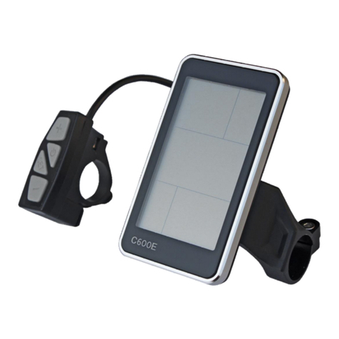
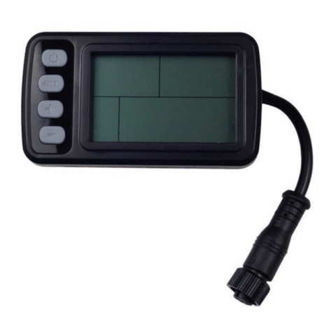
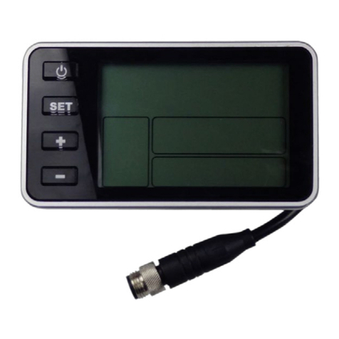
BIGSTONE C200-LCD User manual

C200-LCD Instructions

1
CONTENT
ABOUT THE USER MANUAL.............................................................................................................2
OUTLOOK AND SIZE...........................................................................................................................2
MATERIAL AND COLOR ..................................................................................................................2
BUTTON DEFINITION .........................................................................................................................3
FUNCTION SUMMARY .......................................................................................................................3
FUNCTION SUMMARY .....................................................................................................................3
FULL VIEW AREA ..............................................................................................................................5
NORMAL VIEW AREA.......................................................................................................................5
NORMAL OPERATION........................................................................................................................5
1、ON/OFF .........................................................................................................................................5
2、SPEED DISPLAY .........................................................................................................................6
3、BACKLIGHT INDICATOR ...........................................................................................................6
4、PAS LEVELSELECTION..............................................................................................................6
5、ERROE CODE INDICAYOR.........................................................................................................6
6、SET OPEARATION .......................................................................................................................7
7、DISTANCE INDICATOR ..............................................................................................................8
8、BATTERY INDICATOR................................................................................................................9
9、CABLE DEFINITION ....................................................................................................................9
10、AUTO SLEEP AFTER 5MINUTES ..........................................................................................10
INSTALLATION INSTRUCTION .....................................................................................................10
COMMON PROBLEM & SOLUTIONS............................................................................................11
QUALITY & WARRANTY .................................................................................................................11
QUALITY &WARRANTY:.........................................................................................................11
OTHER ITEMS:.............................................................................................................................12
ERROR CODE TABLE........................................................................................................................12

2
ABOUT THE USER MANUAL
Dear users,
To ensure better performance of your e-bicycle, please read through the
C290 product introduction carefully before using it. We will inform you
all the details concisely(including hardware installation, setting and
normal use of the display)when using our display. Meanwhile, the
introduction will also help you solve possible confusion and malfunction.
OUTLOOK AND SIZE
MATERIAL AND COLOR
C290 products are made of black ABS material the buckle is made of
nylon material. Under the temperature of -20 to 60, the shell material
can ensure normal usage and good mechanical performance of the
products.
Dimension figure (unit: mm).

3
BUTTON DEFINITION
C200 has two buttons including UP and DOWN.
FUNCTION SUMMARY
FUNCTION SUMMARY
C290 provides a wide range of functions and indicators to fit the users’
needs. The indicated contents are as below.

4
1. ON/OFF
2. Speed display
3. Backlight indicator
4. PAS level selection
5. Error code indicator
6. SET operation
7. Distance indicator
7.1 Total distance (ODO)
7.2 Trip distance
8. Battery indicator
9. Cable definition
10. Auto sleep after 5 minutes

5
FULL VIEW AREA
NORMAL VIEW AREA
NORMAL OPERATION
1ON/OFF
Press UP and start the display. The display will provide power for the
controller. With display on, press UP for 3 seconds to turn off the power.
With the display off, there is no battery consumption. The leakage current
is no more than 2 µA. Hold UP for 2 seconds can open the backlight.
※The panel will go to sleep when speed is 0 km/h for 5 minutes.

6
2 SPEED DISPLAY
It displays the current riding speed of e-bike. The speed display is as
below.
3BACKLIGHT INDICATOR
With the power on, click the UP and turn on the backlight. Click it again
and turn off the backlight.
4PAS LEVEL SELECTION
Click UP or DOWN to change the stages and output power ratio, the
output power range from level 1 to level 6 for the default (the levels can
be customized by user) , the default value is level 1.
5ERROE CODE INDICAYOR
If there is something wrong with the electronic control system, the
display will flash at 1 HZ and show the error code automatically.

7
Different error code is corresponding with different fault information,
please see the last page Error code table for details.
Display return to normal only after problem being fixed and bike
will not run before fixing the problem.
6SET OPEARATION
If there is no operation after you enter the set interface, it will auto exit.
6.1 Reset trip distance
Hold UP and DOWN for 2 seconds to clear trip distance. It will be auto
cleared when the trip distance exceeds 2550 km.
6.2 Reset ODO
Hold DOWN for 20 seconds to clear the total riding distance. It will be
auto cleared when the total riding distance exceeds 9999 km.
※This function only for OEMs and distributors use.
6.3 Wheel diameter setting
Hold UP and DOWN for 10 seconds to enter into wheel diameter setting.
Select the accurate wheel diameter value to ensure the accuracy of
display about speed and mileage.

8
※Click UP or DOWN to set the wheel diameter.
6.4 Max speed setting
Hold UP and DOWN for 5 seconds to enter into the speed-limit setting
interface.
The max speed is 45 km/h for the default. User can modify the value of
max speed, when the riding speed exceeds the setting value, the controller
will stop supplying power to the e-bike, in order to ensure the safety of
rider. The max speed ranges from 20 km/h to 45 km/h.
※Click UP or DOWN to select the limited speed. When set max speed
45 km/h, there is no limit for riding speed.
7DISTANCE INDICATOR
With the display on, press UP or DOWN to switch the display
information.
7.1 ODO
The ODO records the driving mileage from using.

9
7.2 Trip distance
Trip distance records the driving mileage, it displays as below.
8BATTERY INDICATOR
When the battery capacity is high, the four battery segments are all
light. When the battery is low, the battery frame will flash. It indicates
that the battery is severely low in voltage condition and needs to be
recharged immediately.
flash
9CABLE DEFINITION
Red: Battery +
Blue: Lock

1
0
Black: Battery –
Yellow: UART- SEND (TXD)
Green: UART-RECEIVE (RXD)
10AUTO SLEEP AFTER 5 MINUTES
When the riding speed is 0 km/h for 5 minutes, the system will go to
sleep automatically.
INSTALLATION INSTRUCTION
The instrument is fixed on the handlebar, adjust the appropriate
perspective, and the button is arranged on the easy control position. In the
case of power failure, the corresponding connector and connector
controller instrument for inserting installation can be completed.
Attentions! Install the instrument from right to left and avoid stretching
buckle over angle.
Step1: Make the snap ring buckle into the handelbar in direction of
the arrow.
Step2: make the instrument slip insert the snap ring from right to
left.

1
1
Step3: Adjust the direction and tighten the low screw after
installation.
COMMON PROBLEM & SOLUTIONS
Q:Why the display is not able to start up?
A:Checking the connector that between display and controller.
Q:How to deal with the error code?
A:Fix it to the maintenance place immediately. If cannot be
resolved, you can go to the electric vehicle repair points repair it in a
timely manner.
QUALITY & WARRANTY
QUALITY & WARRANTY:
1、Any quality problems in normal case and in guarantee
period, our company will responsible for the warranty
2、The warranty time is 18 months from date of
purchasing.

1
2
OTHER ITEMS:
The following items are not belong to warranty scope.
1. It can not be demolished.
2. The damage caused by wrong installation or operation.
3. Shell is broken when display is out of the factory.
4. Wire is broken.
5. Force disaster (such as fire, earthquake, etc.) or natural
disasters like lightning, etc caused by fault or damage.
6. Beyond Warranty period.
ERROR CODE TABLE
The error code is corresponding with the fault definition.
Error code
definition
0
normal
1
Current error or MOS damaged
2
Throttle error(Start detection)
3
motor no phase position
4
Hall error
5
Brake error(Start detection)
6
Under voltage
7
Motor stalling
8
communication controller receiving error
9
communication display receiving error

1
3
Line definition refer to the C200 Fast release wire
Table of contents
Other BIGSTONE Monitor manuals
