Bikeservice BS3510 User manual

BS3510
PROFESSIONAL CHAIN REPAIRING MASTER SET
Instructions
Represent.
BS3506
Chain Link Pliers
BS1164
Drive Chain Tension Puller
BS0353
Chain Adjustable C Hook
Wrench
BS3500
Chain Extractor
RELEVANT PRODUCTS OF CHAIN REPAIR SERVICE
Motorcycle Service Tools
APO TOOL INTERNATIONAL LTD.
No.38 Ping An St, Changhua. Taiwan 50055
T: +886 4 7514888 / F: +886 4 7524888
Website : www.bikeservice.com.tw
The BikeService BS3510 Chain Repairing Master Tool is designed to break chains up to chain
size #632 and press the hollow link pins and plates of the Master Link on chains up to #632.
Please read instructions thoroughly prior to use.
The Tool is designed for hand use (tightened by hand ) utilizing the T-Bar or 3/8” Square and 19mm
with 21mm spanner. The use of Power Tools or extension bars for extra leverage may cause damage
to the tool and should be avoided.
Collocating BikeService products BS3506 Chain Link Clip Pliers and BS1164 Drive Chain
Tension Puller, makes it easier and more convenient to remove and install motorcycle chain.
01
A
B
E
C
D
F1
F2
F3
M
H
L
J
K
G1
K
G2
G3
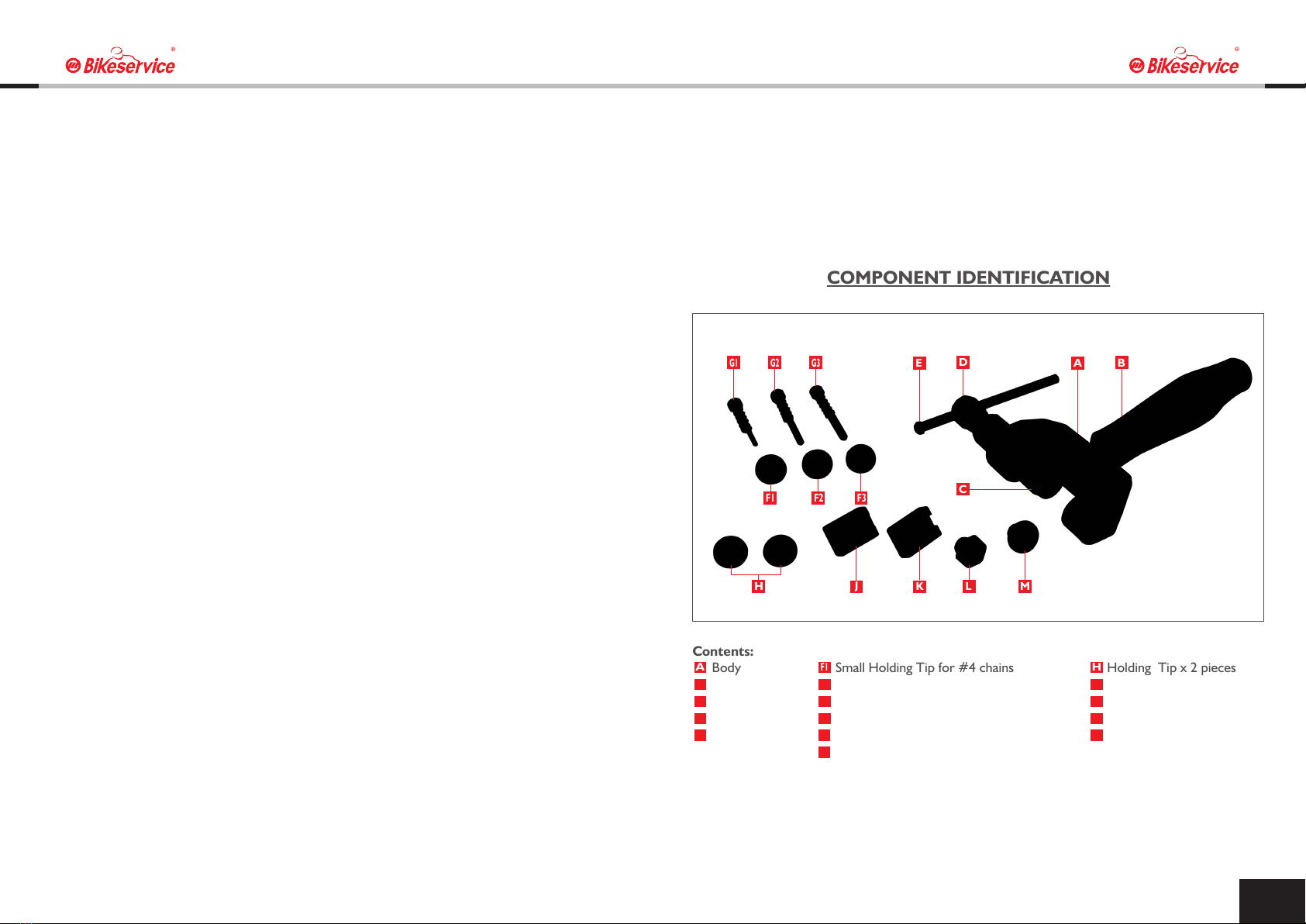
Body
Handle
Center Screw
Forcing Screw
T-Bar
Small Holding Tip for #4 chains
Medium Holding Tip for #5 chains
Large Holding Tip for #6 chains
Small Push Pin w/spring for #4 chains
Medium Push Pin w/spring for #5 chains
Large Push Pin w/spring for #6 chains
Holding Tip x 2 pieces
Shallow Press Block
Deep Press Block
Rivet Tip
Anvil
COMPONENT IDENTIFICATION
Contents:
F2
C
D
F1
A
F3
LH JKM
G1
G2
E
G3
B

02 03
PRODUCT FEATURE(PATENT PENDTING)
This special Forcing Screw adopts a multifunctional driving mode (T bar / 19mm & 21mm Hex Wrench
or Socket / 3/8” Square Driver),which makes the removal and installation process more convenient
and easier in any working environment without having tool specification limits.
You can easily find one of the above tools to do the job.
The new type forged Body adopts three lock holes with
different position and angle which allows a nimble
application in varied space and angle when connecting
the Handle.
Right and Left-Handed operation are both
well-considered in this design and application which
brings users the most ergonomically efficiency during
operation.
Two pieces of special Holding Tip hold the chain in position firmly for chain breaking.
When driving the Forcing Screw, this design can easily hold the Chain Pin in the central hole of the
Holding Tip, efficiently locates and fixes the central point of Chain Pin, and accurately makes the
Chain Pin positioned in right vertical angle. This assists the Chain Pin straying from the right angle or
central position during the operation, and also, this design provides the user with more efficiency and
convenience.
This special Ball Tip design Forcing Screw makes the operation more convenient and effective.
This unique application helps to reduce the direct friction with Push Pin, and avoids the rotation of
Push Pin which will make Push Pin misalign from Chain Pin during chain-breaking process.
Use with T Bar to drive. Use with 3/8” Square Driver tool. Use with 19mm & 21mm
Hex Wrench or Sockets.
Forcing Screw (D)
Special Ball Tip
SKD Push Pin w/spring (G)
Holding Tip (F)
Chain
Push Pin
w/Spring (G)
Push Pin
w/Spring (G)
Center Screw (C)Center Screw (C)
Holding Tip (H)Holding Tip (H)
Holding Tip (F)Holding Tip (F)
Handle hole pisitions.
Lift upper +30°
(Easily applied in varied space
and angle.)
Standard 0°
Holding the Chain Pin in central
Right below -30°
(Easily applied by left-handed user.)
Lift upper +30°Lift upper +30°
Right below -30°
Right below -30°
Stantart 0°
Stantart 0°
04 06
(Fig B) Details the position of the Chain to pressing the chain link pin out.
01. Find out the fixed point of the Chain Link, and use BS3506 Chain Link Pliers for removal of
U clip-type master chain link. (Fig C).
02. Ensure the Chain is positioned straight with the Chain Pin head over the hole in the Body of the
tool. To assist in the pin pressing operation grind flat the mushroomed head of the chain link pin.
Ensure the pressing pin is aligned.
03. Twisting of the Tool or misalignment could cause damage to the tool and the Push Pin.
Place the Chain Pin exactly between the hole of two sides of Holding Tip (F and H in Fig A).
Adjust the Center Screw to fix the Chain Link. The underside of the link pin should
be aligned over the hole in the tool Body to allow the chain link pin to be pressed into the hole.
04. Using the T-Bar or a 19mm spanner, turn the Forcing Screw the Push Pin to push the Chain Pin
out of the chain link.
05. Repeat the Operation 3. to push the other pin out from the Chain Link to complete the chain
breaking.
As chain sizes vary so do the pin sizes depending on the size of the chain links. The Tool breaking pins
in the kit cover sizes to suit the following chain links.
(F1) Small Holding Tip and (G1) Smaill Push Pin w/Spring, suits chains size #415, #420 and #428.
(F2) Medium Holding Tip and (G2) Medium Push Pin w/Spring, suits chains size #520, #525, #530
(#50) and #532.
(F3) Large Holding Tip and (G3) Large Push Pin w/Spring, suits chains size #630 and #632.
(H) Holding Tip for all chains.
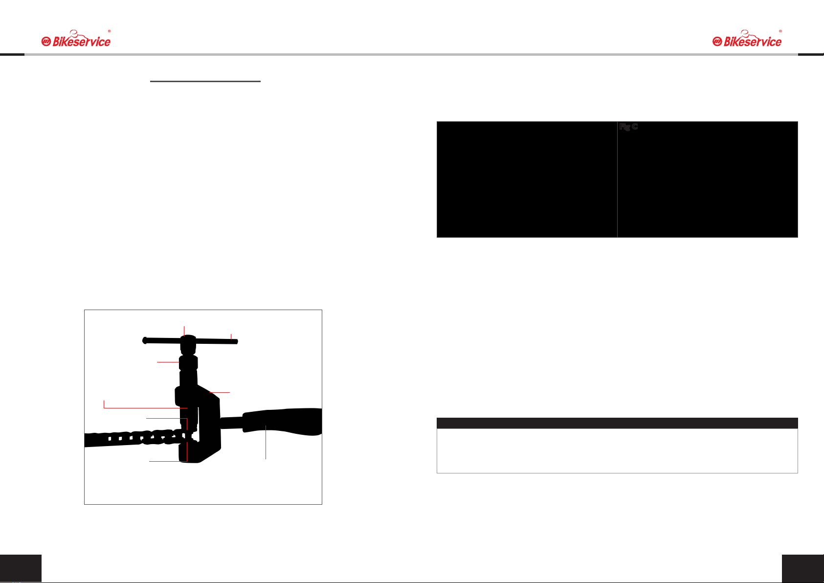
(Fig A) Details the correct assembly of the Tool for breaking the Chain Pin.
Assembly of the Tool
01. Screw the Center Screw into the Tool Body.
02. According to the size of chain, choose corresponding Holding Tip (F) for the Center Screw and
Holding Tip (H) for the Body bottom. and lock them on the screw threaded body two sides .
03. Select the correct size Push Pin, with spring according to the chain size and assemble.
Then insert the Push Pin into the centre of the Center Screw.
04. Screw the Forcing Screw or T-Bar into the Center Screw to hold in position.
Make sure the Push Pin is well operated into the centre of the Holding Tip (F) during the
operation. Ensure that the Push Pin is retracted from the nosepiece, prior to preparing the operation.
05
Fig B Fig C
Fig C
Should the chain link pin not press out do not use excessive force as this may damage the tool.
Check the tool for alignment , disassemble the tool if necessary and reassemble , align and
commence the operation as detailed above.
CAUTION
BREAKING CHAINS
T Bar (E)
Forcing Screw (D)
Center Screw (C)
Holding Tip (F)
Body (A)
Handle (B)
Push Pin w/spring (G)
Holding Tip (H)
Fig A

ASSEMBLY CHAIN PRESSING SIDE PLATES
Parts:
(H) Holding Tip x 2 pieces
(J) Shallow Press Block
(K) Deep Press Block
For All motorcycle chain size:
#415, #420, #428, #520, #525,
#530 (#50), #532 and #630, #632.
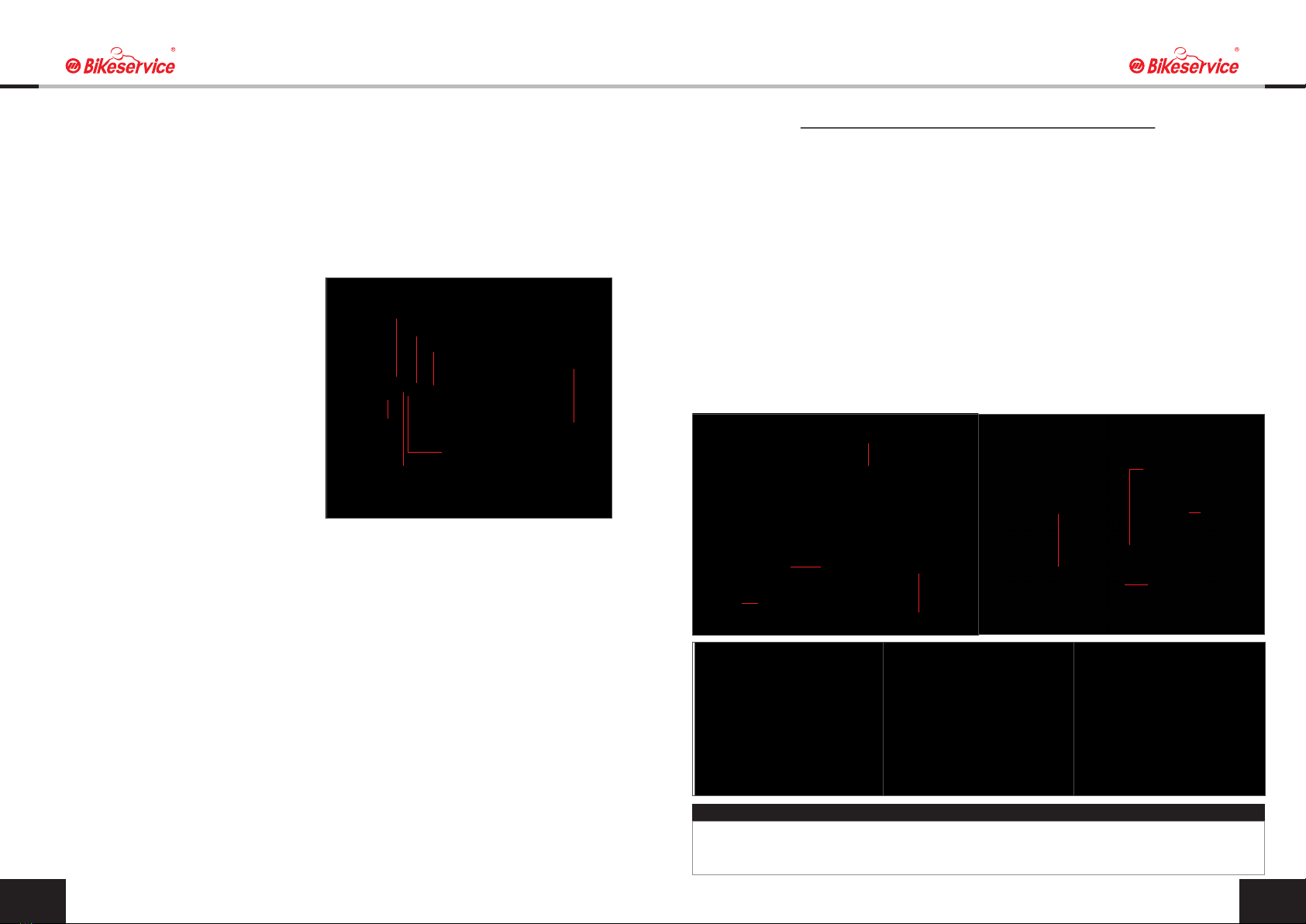
Assemble the tool as shown in (Fig D) for pressing side plates.
01. Thread the Center Screw into the Body of the tool.
02. 2 pieces Holding Tip (H) of the Center Screw and Body bottom, and lock them on screw
thread at two sides.
03. Refer to (Fig D) as there are 2 pieces Press Block, Shallow (J) and Deep (K), and lock into
the 2 sides Holding Tip (H) hole of the Center Screw and Body bottom.
04. The Shallow Press Block (J) is positioned base plate of the tool (fixed master link side)
and the Deep Press Block (K) on the Center Screw side end of the tool with the Master
link plate underneath.
(The installation direction depends on the chain link, Deep Press Block is distance
of chain pin protrusion.)
05. This tool can be used to quickly remove the chain by conversely assembling the Shallow
Press Block (J) on Center Screw and Deep Press Block (K) on the bottom of Body, and then
repeating the Fig.E-Action.7.
(Different chains may require different operation.)
(Fig E) Chain assembly and riveting or mushrooming the head of hollow link pins. Riveting process is
not required on solid link pin style master links with elongated U clip retainers.
01. Check the chain manufacturer’s instruction or workshop manual for installation.
02. Install the new chain over the pulley’s sprockets and swing arm.
03. Use BS1164 Drive Chain Tension Puller to fix the distance of Master Link
04. Using the new Master link grease the O-Rings and place these on the master link pins.
05. Join the chain using the master link from the back of the chain with the pins facing outwards.
The rear sprocket will provide a position for the links to be joined easily.
06. Grease the Master link pins and install the O-Rings onto the hollow pins and then position the
Master link backing plate. Greasing the backing plate will hold the plate in position prior to
riveting. Note Ensure that the O-Rings are on the underside of the backing plate.
07. Using the Forcing Screw or 21mm spanner tighten the Center Screw checking that the link is
correctly aligned.
08. Compress the chain link until the chain Master link pins protrude above the Master link backing
plate.
09. Ensure that the link is evenly compressed on both sides. This measurement can be easily
checked with a vernier caliper. Refer to the chain manufacturers specification of recommended
protrusion as this may vary depending on the brand of chain.
10. For Master Link U Clip design attach the U clip ensuring, Using BS3506 Chain Link Pliers to
install that the U clip locks the backing plate firmly in position. (Fig F)
06 07
BS1164
Drive Chain
Tension Puller
BS1164
Drive Chain
Tension Puller
Shallow Press Block (J)
Deep Press Block (K)
Center Screw (C)
Center Screw (C)
21mm Wrench
Fig F
Fig E
Center Screw (C)
Body (A)
Holding Tip (H)
Holding Tip (H)
Shallow Press Block (J)
Deep Press Block (K)
Fig D
Solid Pin U-Clip Master
Link
Solid Pin U-Clip Master
Link Assembled
Hollow Pin Rivet Master
Link
Hollow Pin Rivet Master
Link Assembled
Master Link Identification
Chain assembly and riveting or mushrooming the head of hollow link pins. Riveting process is not
required on solid link pin style master links with elongated U clip retainers.
Please pay attention that if the chain pin and side link are positioned correctly when repeat using
Master Chain Link. If they are in the wrong position, please repeat the Breaking Chain Operation 4.
using Push Pin to fix the chain pin at the point of side link. Please check the figure.
(Fig H) Refer to the chain manufacturer's specifications for distance of chain pin protrusion, and
direction and installation of master link clips.
All chains are different, and BikeService cannot provide the exact specification for your chain.
Holding Tip (H)
Holding Tip (F)
Chain Side
Link Push Pin w/spring (G)
Center Screw (C)
Forcing Screw (D)
Chain Pin
Fig H
Fig J
08 09
Assembly of the Tool
01. Reassemble the tool to rivet or mushroom the hollow pins. (Fig L)
02. Thread the Center Screw into the Body of the tool.
03. Assemble the Rivet Tip into the Center Screw end thread and the Anvil in the thread of the tool.
04. Using a 21mm spanner firstly tighten the Center Screw checking that the link is correctly aligned.
05. Tighten the Forcing Screw either via the T-bar or 21mm spanner ensuring the tool Rivet is
centered on the Master Link Pin. (Fig J)
06. Remove and repeat this procedure on the second Master Link Pin.
07. Check that the Master link Pins are correctly Riveted as per the chain manufacturers
recommendation. (Fig K)
08. Do not over tighten as this can cause damage to the Master Link hollow pin or the Tool riveting
pin.
RIVETING MASTER LINK HOLLOW PINS
Center Screw (C)
21mm wrench
Rivet Tip (L)
Anvil (M)
Riveting chain pin
Anvil (M)
Rivet Tip (L)
Center Screw (C)
Check the line of sight to ensure that the chain is aligned straight.Tension the chain and align the
wheel to the manufacturers specification.
IMPORTANT
Fig K
Fig L
Table of contents


