Bilberry Stoves 5kW Stove Manual

BILBERRYSTOVES
5kW / 8kW / 10kW
Installation & Operating Instructions
10kW 8kW
5kW

TABLE OF CONTENTS
PAGE NO.
1. Installation Instructions . . . . . . . . . . . . . . . . . . . . . . . . . . . . . . . . . . . . . . . . . . . . . . . . . . . . . . . . . . .3
2. Pre-Installation Checks . . . . . . . . . . . . . . . . . . . . . . . . . . . . . . . . . . . . . . . . . . . . . . . . . . . . . . . . . . .3
3. Technical Data. . . . . . . . . . . . . . . . . . . . . . . . . . . . . . . . . . . . . . . . . . . . . . . . . . . . . . . . . . . . . . . . . .3
4. Installation . . . . . . . . . . . . . . . . . . . . . . . . . . . . . . . . . . . . . . . . . . . . . . . . . . . . . . . . . . . . . . . . . . . . .3
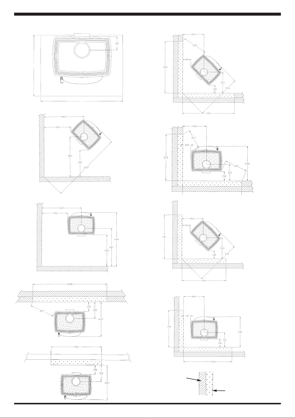
5. Clearance to Combustibles - 10kW Stove . . . . . . . . . . . . . . . . . . . . . . . . . . . . . . . . . . . . . . . . . . . .4
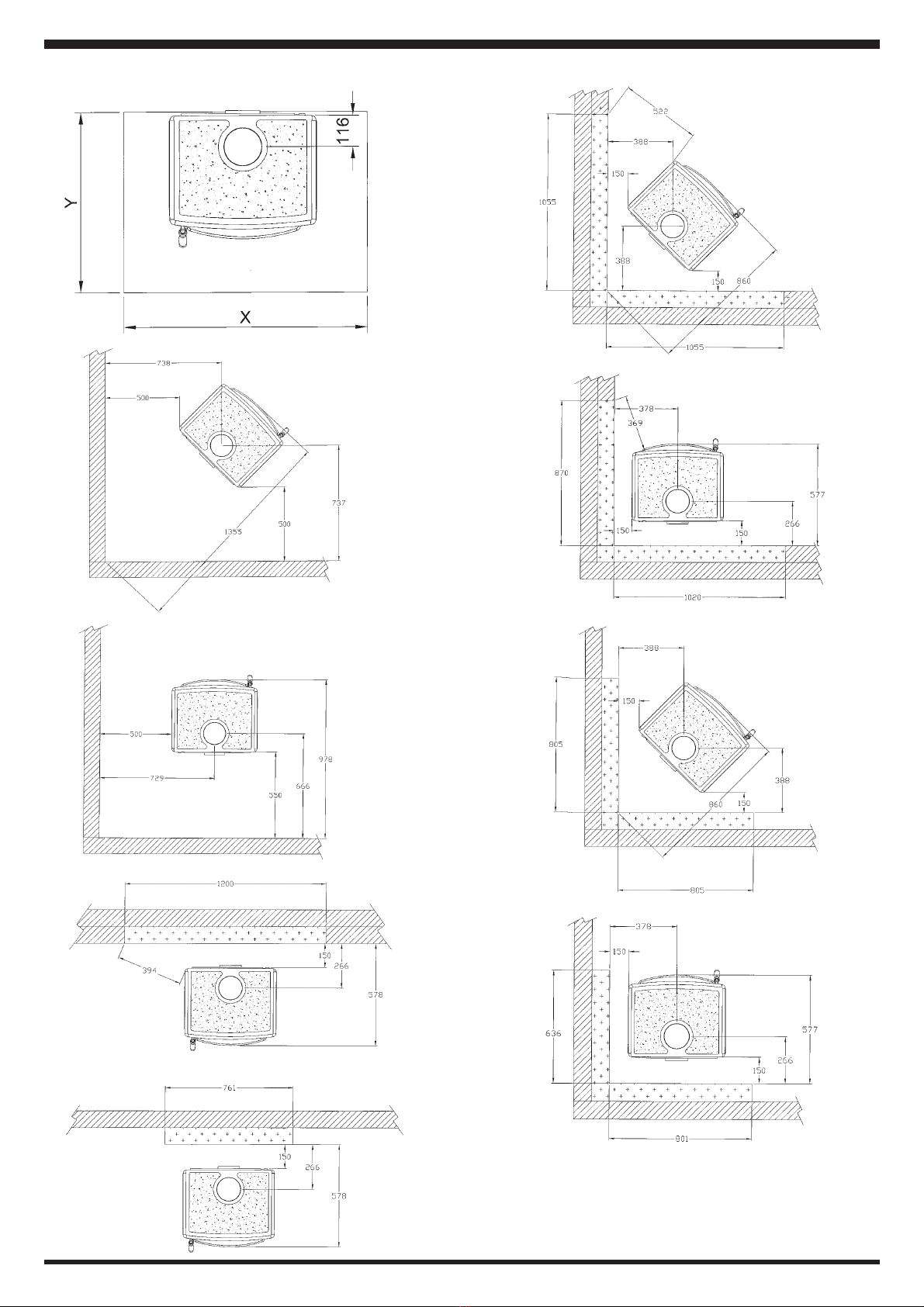
6. Clearance to Combustibles - 8kW Stove . . . . . . . . . . . . . . . . . . . . . . . . . . . . . . . . . . . . . . . . . . . . .5
7. Clearance to Combustibles - 5kW Stove . . . . . . . . . . . . . . . . . . . . . . . . . . . . . . . . . . . . . . . . . . . . .6
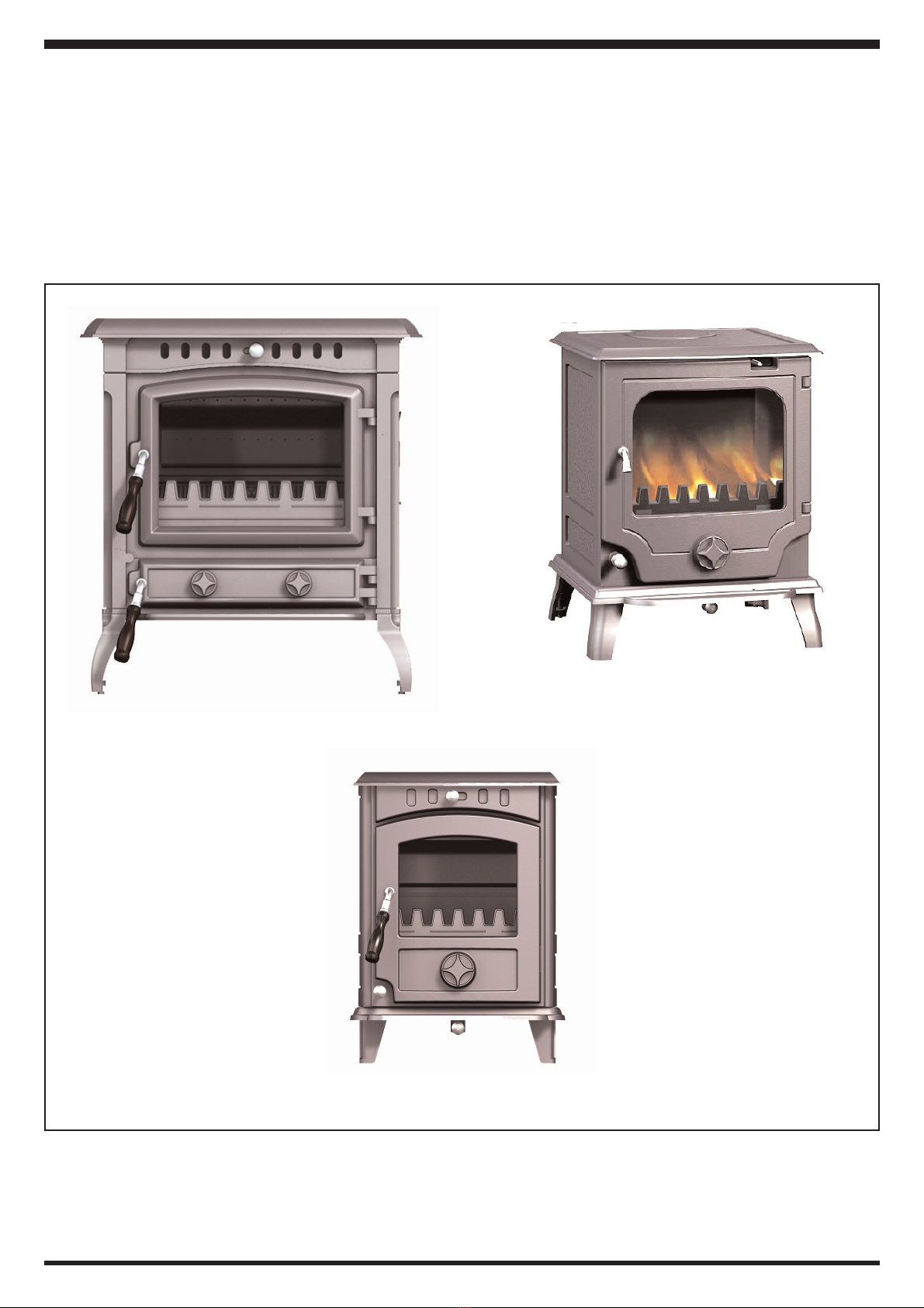
8. Stove Dimensions . . . . . . . . . . . . . . . . . . . . . . . . . . . . . . . . . . . . . . . . . . . . . . . . . . . . . . . . . . . . . . .7
9. Mantle Clearances . . . . . . . . . . . . . . . . . . . . . . . . . . . . . . . . . . . . . . . . . . . . . . . . . . . . . . . . . . . . . .8
10. Ceiling Protection . . . . . . . . . . . . . . . . . . . . . . . . . . . . . . . . . . . . . . . . . . . . . . . . . . . . . . . . . . . . . . .8
11. Chimney . . . . . . . . . . . . . . . . . . . . . . . . . . . . . . . . . . . . . . . . . . . . . . . . . . . . . . . . . . . . . . . . . . . . . .8
12. Flues . . . . . . . . . . . . . . . . . . . . . . . . . . . . . . . . . . . . . . . . . . . . . . . . . . . . . . . . . . . . . . . . . . . . . . . . .9
13. Flue Pipes . . . . . . . . . . . . . . . . . . . . . . . . . . . . . . . . . . . . . . . . . . . . . . . . . . . . . . . . . . . . . . . . . . . . .9
14. Connecting to a Steel Chimney . . . . . . . . . . . . . . . . . . . . . . . . . . . . . . . . . . . . . . . . . . . . . . . . . . . .10
15. Fresh Air Supply . . . . . . . . . . . . . . . . . . . . . . . . . . . . . . . . . . . . . . . . . . . . . . . . . . . . . . . . . . . . . . . .10
16. Draught Conditions . . . . . . . . . . . . . . . . . . . . . . . . . . . . . . . . . . . . . . . . . . . . . . . . . . . . . . . . . . . . . .11
17. Operating Instructions . . . . . . . . . . . . . . . . . . . . . . . . . . . . . . . . . . . . . . . . . . . . . . . . . . . . . . . . . . . .11
18. Suitable Fuels . . . . . . . . . . . . . . . . . . . . . . . . . . . . . . . . . . . . . . . . . . . . . . . . . . . . . . . . . . . . . . . . . .11
19. Use . . . . . . . . . . . . . . . . . . . . . . . . . . . . . . . . . . . . . . . . . . . . . . . . . . . . . . . . . . . . . . . . . . . . . . . . . .11
20. Air Control . . . . . . . . . . . . . . . . . . . . . . . . . . . . . . . . . . . . . . . . . . . . . . . . . . . . . . . . . . . . . . . . . . . . .11
21. Use With Wood . . . . . . . . . . . . . . . . . . . . . . . . . . . . . . . . . . . . . . . . . . . . . . . . . . . . . . . . . . . . . . . . .12
22. Use With Solid Fuel . . . . . . . . . . . . . . . . . . . . . . . . . . . . . . . . . . . . . . . . . . . . . . . . . . . . . . . . . . . . .12
23. Disposal of Ashes . . . . . . . . . . . . . . . . . . . . . . . . . . . . . . . . . . . . . . . . . . . . . . . . . . . . . . . . . . . . . . .13
24. Safety Notes . . . . . . . . . . . . . . . . . . . . . . . . . . . . . . . . . . . . . . . . . . . . . . . . . . . . . . . . . . . . . . . . . . .14
25. CO Alarm . . . . . . . . . . . . . . . . . . . . . . . . . . . . . . . . . . . . . . . . . . . . . . . . . . . . . . . . . . . . . . . . . . . . . .14
26. Maintenance . . . . . . . . . . . . . . . . . . . . . . . . . . . . . . . . . . . . . . . . . . . . . . . . . . . . . . . . . . . . . . . . . . .15
27. Warranty Policy . . . . . . . . . . . . . . . . . . . . . . . . . . . . . . . . . . . . . . . . . . . . . . . . . . . . . . . . . . . . . . . . .15
28. Trouble Shooting . . . . . . . . . . . . . . . . . . . . . . . . . . . . . . . . . . . . . . . . . . . . . . . . . . . . . . . . . . . . . . . .16
29. Exploded View 10kW . . . . . . . . . . . . . . . . . . . . . . . . . . . . . . . . . . . . . . . . . . . . . . . . . . . . . . . . . . . .17
30. Exploded View 8kW . . . . . . . . . . . . . . . . . . . . . . . . . . . . . . . . . . . . . . . . . . . . . . . . . . . . . . . . . . . . .18
31. Exploded View 5kW . . . . . . . . . . . . . . . . . . . . . . . . . . . . . . . . . . . . . . . . . . . . . . . . . . . . . . . . . . . . .19
32. Sales & Service . . . . . . . . . . . . . . . . . . . . . . . . . . . . . . . . . . . . . . . . . . . . . . . . . . . . . . . . . . . . . . . . .20
2

BILBERRYSOLID FUEL STOVES
INSTALLATION INSTRUCTIONS
3
PRE-INSTALLATION CHECKS
Installation of a stove must be done according to local codes and regulations. National and European standards
must be observed when installing this product.
Please read the Installation & Operation manual enclosed with this product before use.
TECHNICAL DATA 5kW Stove 8kW Stove 10kW Stove
Material: Cast Iron Cast Iron Cast Iron
Finish: High Temp Resistant Paint High Temp Resistant
Paint
High Temp Resistant Paint
Fuel: Solid Fuel Solid Fuel Solid Fuel
Log Length - Max.: 32 cm 35 cm 41 cm
Flue Outlet: Top & Rear Top & Rear Top & Rear
Flue Pipe Dimension- ID:- 125mm 125mm 150mm
Weight [Approx.]: 70kgs 80kgs 148kgs
Dimensions: W 400 x H 553 x D 383 W 457 x H 583 x D 426 W 583 x H 634 x D 482
Nominal Heat Output: 5kW 8kW 10kW
Recommended Chimney
Draught:
0.06” w.g. min. 0.06” w.g. min. 0.06” w.g. min.
Operational Mode: * Intermittent * Intermittent * Intermittent
* Note: Intermittent combustion in this context means normal use of the stove, i.e. fuel is added as soon as
the fuel has burned down.
INSTALLATION
Unpacking The Stove
After removing the outer packaging, unbolt the combustion chamber from the wooden pallet and place it gently
on its back. The cardboard packaging can be placed underneath to prevent damaging the stove. Remove the
leg pack from the stove and bolt each leg securely to the underside of the base on the combustion chamber,
using the bolts provided (these can be found inside the stove).
We recommend that two people perform the assembly and installation procedure.
Installing The Stove
The stove and chimney installations MUST comply with current National & Local Building Regulations; your
approved dealer or your local building officer can advise regarding this. Ultimately, it is you and your installer
who is responsible that the installation complies.
Floor Protection
If installing this stove on a combustible floor, floor protection must be provided, consisting of a layer of noncom-
bustible insulation material 10mm thick. This insulation can then be covered with 3mm sheet metal. This insu-
lation material should extend past the sides and front of the stove, 400mm to front and 200mm to the sides.

CLEARANCES TO COMBUSTIBLES - 10kW STOVE
Y
X
4
Combustible wall
Non Combustible wall

5
CLEARANCES TO COMBUSTIBLES - 8kW STOVE

CLEARANCES TO COMBUSTIBLES - 5kW STOVE
6
X
Y

STOVE DIMENSIONS
Bilberry 5kW
Bilberry 10kW
Bilberry 8kW
Note: Dimensions stated are in millimetres unless
otherwise stated and may be subject to a slight +/- variation.
7

8
CEILING PROTECTION
There must be a minimum distance of 1200mm to a combustible ceiling above the fireplace.
Clearances to Furniture & Soft Furnishings
We recommend the stove be installed 800mm from combustible material. Serious consideration should also be
given to positioning of any furniture that could be adversely affected by heat. The clearances to combustible
materials in front of the stove should be a minimum of 800mm. When lighting, a solid fuel stove will get very
hot and therefore adequate protection must be provided, particularly in situations where there is a safety risk to
children or the infirm. Asuitable safety guard around the stove should be considered.
CHIMNEY
The stove is a radiant room heater and must be connected to a chimney of the proper size and type. The chim-
ney must have a diameter of at least 6” (150mm). It is best to connect to a chimney of the same size, as con-
nection to a larger size may result in a somewhat less draught.
Do not connect to a chimney serving another appliance. Minimum chimney height 15’ (4.5 meters) from floor
on which stove is installed. An existing masonry chimney should be inspected and if necessary repaired by a
competent mason. The stove must be connected to a chimney with a minimum continuous draft of .06” wg (15
Pascals). Poor draft conditions will result in poor performance.
Chimneys for use with solid fuel appliances should be capable of withstanding a temperature of 1100oC with-
out any structural change which would impair the stability or performance of the chimney.
If the stove is fitted in place of an open fire then the chimney should be swept again, one month after installa-
tion, to clear any soot falls which may have occurred due to the difference in combustion between the stove and
the open fire.
BS EN 15287-1:2007, Design Installation and Commissioning of Chimneys; Part 1: Chimneys for non-room-
sealed heating appliances should be used.
MANTLE CLEARANCES
Fig.1
Fig.3
5kW 8kW
10kW
Fig.2
The minimum mantle clearance to combustibles
required are:-
5kW - 550mm to the top
500mm to the sides
8kW -550mm to the top
500mm to the sides
10kW -550mm to the top
550mm to the sides

FLUE PIPES
Aflue pipe should only be used to connect an appliance to a chimney and should not pass through any roof
space.
Flue pipes may be of any of the following materials:
(a) Cast iron as described in BS 41: 1973 (1981), or
(b) Stainless steel with a wall thickness of at least 1mm and as described in BS EN 10095:1999 Specification
for stainless and heat resisting steel plate, sheet and strip, for Grade 316 S11, 316 S13, 316 S16, 316 S31,
316 S33, or the equivalent Euronorm 88-71 designation, or
(c) Vitreous enamelled steel complying with BS 6999: 1989.
Fig.4
9
FLUES
Flues should be vertical wherever possible and where a bend is necessary, it should not make an angle of more
than 45owith the vertical. Horizontal flue runs should be avoided except in the case of a back outlet from the
appliance, when the length of the horizontal section should not exceed 150mm.
In order to minimise flue resistance and to make sweeping easier it is recommended to use 2 x 45obends rather
than a 90obend.
The flue termination point must be located to minimise any wind effects. Wind effects of suction, pressure zones
and turbulence can be created by the roof and adjacent objects. Wind effects can also be created by natural
land contours.
To minimise the wind effects, the flue termination point should be located a minimum of 1000mm from the roof
measured vertically and 2300mm measured horizontally. Where this termination point does not suffice it may
be necessary to extend the flue pipe so that the termination point is above the apex. See Fig.4.

Fig 5
CONNECTING TO ASTEEL CHIMNEY
If your installation involves taking the chimney straight up and through the ceiling, you must comply with
National, Local and Building Regulations or flue manufacturers instructions concerning clearances to com-
bustible materials such as walls, floor joists and ceilings. The joint between the stove flue collar and the stove
pipe must also be sealed using the fire cement. It is important that the insulated flue system is properly sup-
ported both at ceiling level and at roof level. THE STOVE MUST NOT BEAR THE WEIGHT OF THE CHIM-
NEY SYSTEM (see chimney manufacturer’s instructions). Excessive weight on the stove will
inhibit expansion and could lead to damage of the stove top. Damage caused to the stove in this way would
not be covered by the Manufacturers Warranty.
IN THE EVENT THAT ACHIMNEY FIRE OCCURS RESULTING FROM FAULTY OPERATION OR PRO-
LONGED USE OF DAMP WOOD FUEL, CLOSE THE AIR VENTS COMPLETELYAND CONTACT YOUR
LOCAL FIRE DEPARTMENT IMMEDIATELY.
CAUTION
The chimney should be swept at least twice by a competent and approved person. All chimney joints should
be inspected during cleaning.
FRESH AIR SUPPLY
Asolid fuel appliance requires a continuous supply of air to support combustion. If another air using appliance
such as extractor hood or clothes dryer is installed in the same or an adjacent room, the ventilation supply will
need to be increased to ensure there is adequate air for ventilation and combustion when all appliances are in
operation.
In houses equipped with mechanical ventilation an external vent must be installed to provide adequate air for
combustion.
Properly installed solid fuel unit will give even the most efficient houses a pleasant and natural ventilation.
10
Flue pipes with spigot and socket joints should be fitted with the socket uppermost and all joints should be
sealed with fire cement.
Clearance to combustibles must be adhered to when fitting the flue pipe.
The flue outlet spigot for this appliance is inside the burn chamber during transportation. You can choose
between top or rear outlet from the flue pipe. (Fastening screws are included with the stove).
Flue pipes are placed directly onto the product flue outlet, there are 3 screw holes to secure the flue pipe in
place. See Fig.5.
Note: It is important that the joints are completely sealed using a suitable fire cement. Air leakage etc may lead
to malfunction.

DRAUGHT CONDITIONS
If smoke spillage occurs when the firedoor is opened, it is probably due to poor chimney draught. This type of
stove requires at least 0.06” w.g. of chimney draught to achieve satisfactory combustion and smoke spillage
prevention. However, in cases where the stove door is opened too vigorously you could expect that slight
smoke spillage may occur.
If you have any doubts, you may want to have your installer measure the draught in the chimney.
The chimney’s draught is the resulting effect within the flue caused by the difference in temperature within the
flue and the cooler temperature outside. Other factors that can influence the level of draught include the length
of the flue, insulation of the chimney, adverse weather conditions, tall buildings or trees nearby the flue termi-
nal.
11
BILBERRYSOLID FUEL STOVES
OPERATING INSTRUCTIONS
SUITABLE FUELS
COAL, ANTHRACITE, PEAT, WOOD SYNTHETIC LOGS, OR OTHER FUELS. “Never use gasoline” gasoline
type lantern fuel, kerosene, charcoal lighter fluid or similar liquids to start or ‘freshen up’ a fire in this heater.
Keep all such liquid well away from the heater while in use. Operate stove only with fuelling door and ashpit
doors closed. This heater is hot whilst in operation. Keep children, clothing and furniture a safe distance away.
The stove output levels are assessed on standard House Coals of good quality. Reduced outputs will result
when fuels of lower calorific values are used. Wood logs up to 406mm (16”) long are suitable.
All fuels should be stored under cover and kept as dry as possible prior to use.
NEVER BURN HOUSEHOLD RUBBISH OR ANY FORM OF PETROLEUM BASED COKE IN THIS STOVE.
USE
Odours on First Lighting of The Stove:
Painted stoves may emit an unpleasant odour when used for the first time. The room must be thoroughly ven-
tilated. (ie. it is recommended to open all windows in the room in which the appliance is fitted). Let the fire
burn with a high draught until all traces of the odour have dissipated and no smoke or smells can be detected.
AIR CONTROL
The amount of heat produced by the stove is regulated using three air controls. The primary air supply, where
air passes up through the riddling grate, is controlled using the spin valve, and the secondary air (airwash sys-
tem), which is supplied to the combustion over the glass and is controlled using the upper air control. Athird
air inlet (normally named secondary air) provides a constant, pre-heated air supply to the combustion just above
the fire, it is controlled using the air control below the ash lip. This air supply doesn’t normally need to be reg-
ulated, however it is necessary to keep this air supply open always.
WARNING
ENSURE TOP BAFFLE IS CORRECTLYIN
PLACE BEFORE LIGHTING THE STOVE.
See Fig.6.
Fig.6
Top Baffle in Place

USE WITH WOOD
Lighting:
*Slide the top air control to open and open the spin valve.
*Lay firelighters or rolled up newspapers on the grate with a reasonable quantity, if necessary, of dry kindling,
place 2 or 3 small logs on top.
*Light the newspaper or firelighters using a long taper and close the door.
*When the fire is lighting well, add further logs of a diameter up to 10cms.
*When the stove body is very hot, close the spin valve.
*The burning rate can now be controlled by moving the top air control.
Refuelling:
*Slide the top air control to open, and open spin valve fully.
*Open the door slowly to avoid a sudden rush of air intake, causing smoke to escape into the room and then
refuel.
*Leave the spin valve open for a few minutes to allow the initial volatiles in the wood to burn.
*Close the spin valve.
IMPORTANT:Wood contains a large amount of volatiles which need to be ignited quickly to prevent blow-back.
If the wood just lies smouldering, especially after re-stoking, a lot of smoke is created, which in the worst case
may cause an explosive ignition of the gases resulting in damage to the stove.
In order to ignite the gases that are released from the wood, and to keep clear lasting flames during the com-
bustion process, it is important to let in the required quantity of oxygen (air supply) at all times. The setting of
the air supply, the method of ignition and the lighting intervals depend on the draught in the chimney, the wind
and weather, and amount of heat required, fuel etc.. This means that it may take some time before you get to
know the correct functioning of the stove under any given circumstances.
USE WITH SOLID FUEL
Lighting:
*Slide the top air control to open and open the spin valve.
*Lay firelighters or rolled up newspapers on the grate with a reasonable quantity of dry kindling. Place a small
amount of solid fuel on top.
*Light the newspaper or firelighters using a long taper and close the door.
*When the fire is burning well, add further fuel.
*When the stove body is hot, close the top air control.
*The burning rate can now be adjusted by the spin valve.
Refuelling:
*Open the spin valve fully.
*Open the door slowly to avoid a sudden rush of air intake, causing smoke to escape into the room and then
refuel.
*Leave the spin valve open for a few minutes to allow the initial volatiles in the fuel to burn.
*Adjust the spin valve to the desired position.
12

13
Air Regulation
Fig 7
Close
Open
*If the stove is lit using wet wood, a lot of the fuel’s thermal energy will be spent forcing the water out
of the wood, without releasing any heat to the stove. This incomplete combustion results in a layer
of soot being left in the stove, pipe and chimney.
DISPOSAL OF ASHES
It is essential to keep the grate free from a heavy build up of ashes. This product is equipped with a grate rid-
dling tool which is used to shake ashes off the grate into the ashpan. Whenever the stove is burning low, and
the spin valve is open, use the riddling lever to clear the grate of surplus ashes.
If burning solid fuel, always empty the ashpan at least once a day or whenever it is full of ashes. Never allow
the ashpan to over-fill allowing ash to be in contact with the underside of the grate. If this condition is allowed,
the grate will burn out prematurely.
DO NOT TRANSPORT HOT ASHES FROM THE STOVE USING THE ASHPAN OR THE OPERATING TOOL.
Ashpan
Operating Tool
Fig.8

SAFETY NOTES
1. Clean the flue-ways of the stove every week and ensure that there are no
blockages. Please refer to manual for instructions.
2. Never allow a build up of ashes in the ash pan, as this will cause the grate to burn
out prematurely.
3. Do not burn rubbish/household plastic.
4. Do not leave ash-door open during operation as this will over heat the unit
causing unnecessary damage.
5. Clean the chimney at least twice a year.
6. Keep all combustible materials a safe distance away from unit, please consult
section on clearance to combustibles.
7. For safety reasons never leave children unaccompanied while stove is in use.
8. Avoid contact with unit when in use as stove reaches very high operating
temperatures.
14
CO ALARM
We recommend the fitting of a CO Alarm in the same room as the appliance, this is a requirement under UK
Building Regulations. Further guidance on the installation of a carbon monoxide alarm is available in BS EN
50292:2002 and from the alarm manufacturers instructions.
Provision of an alarm must not be considered a substitute for either installing the appliance correctly
or ensuring regular servicing and maintenance of the appliance and chimney system.
WARNING:-
If the CO Alarm sounds unexpectedly:-
1. Open Doors and windows to ventilate the
room and then leave the premises.
2. Let the fire go out.

MAINTENANCE
Cleaning The Glass:
This product is equipped with an air wash for the glass. Air is sucked in through the air vent above the door
and down along the inside of the glass.
However, some soot will always stick to the glass, but the quantity will depend on the draught conditions and
adjustment of the air wash vent. Most of the soot layer will normally be burned off when the air wash vent is
opened all the way and a fire is burning briskly in the fireplace.
Note - To clean glass, use an approved suitable stove glass cleaner in accordance with the manufacturers
instructions.
External Surface Cleaning:
The cast surface of the stove is painted with heat-resistant paint. It is best maintained by simply vacuuming it
with a soft brush attachment or wiping it down with a dry, dust-free cloth.
Over time, the painted surface of the stove can turn a greyish colour, however it can easily be freshened up with
a spray paint which is available from your local retailer.
Gaskets:
The gaskets in the door will wear out over time, and should be replaced as required in order to prevent
overfiring.
15
WARRANTY POLICY
Your Bilberry Stove carries a guarantee against manufacturing defects for a period of one year from date of
purchase. This guarantee shall not apply to any part that has been altered in any way, or which in our judge-
ment has been subjected to misuse, neglect, accident, abuse and wear & tear. Variations in colour and
texture are a natural characteristic of cast iron products. Colour changes may result from exposure to light and
other elements which are a part of the aging process. These material variations and changes are not covered
by the warranty.
The Guarantee would not be extended to Items which would be subject to wear & tear such as firebox linings,
firebox bricks, baffle, grate parts, fire fence, ash pan, operating tool, door glass, door rope and gasketing
material.
Claims are not valid where the installation does not conform to Manufacturers Recommendations and
Appropriate Building Regulations.
In the unlikely event of any failure of components covered by this guarantee, we will replace them free of
charge to return the stove to its original specification. Labour costs excluded.

TROUBLE SHOOTING
PROBLEM POSSIBLE CAUSE ACTION
Fire difficult to start - Unseasoned wood, too damp or
poor quality.
Logs too big
Use recommended fuel only.
To light fire use small, very dry
twigs. To maintain fire use split
logs.
Fire Goes Out Air Starvation
Insufficient Draught
Open lower spin wheel and top air
control lever.
Check that the flue is not obstruct-
ed, sweep if necessary - (seek
advice from a chimney specialist).
Fire Burns Too Quickly Too much draught
Poor Quality Wood
Ensure that the lower spin wheel is
closed and partially close the top
air control lever.
Do not continuously burn small
wood, sticks, bundles , carpentry
off-cuts (plywood / pallets etc)
Smokes When Lighting Up Flue duct is cold Burn paper and kindling to
increase heat.
Smokes While Burning Draught is insufficient
Down Draught
Room is in decompression
Consult a chimney specialist.
Check that the flue is not obstruct-
ed, sweep if necessary.
Install an anti-down draught cowl.
Consult your dealer.
In houses equipped with
Mechanical Ventilation, an outside
air intake must be installed for the
chimney.
Low Heat Output Incorrect Fuels Use the recommended Fuel
16

10kW EXPLODED VIEW
1. BASE SM08601WF
2. HOB SM08602WF
3. FRONT SM08603
4. BACK SM08604
5. LH SIDE PANEL SM08605WF
6. RH SIDEPANEL SM08606WF
7. FIRE DOOR SM08607
8. ASH DOOR SM08608HM
9. AIR WASH COVER SM 08609
10. AIR WASH SHUTTER SM086010
11. BACK BRICK SM08611
12. LH SIDE BRICK SM08612
13. RH SIDE BRICK SM08613
14. FIRE BED SM08614
15. GRATE SM08615
16. MIDDLE BAFFLE SM08616
17. LOWER BAFFLE SM08617
18. TOP BAFFLE SM08618
19. FIRE FENCE SM08620WF
20. LEFT GRATE REST SM08621
21. RIGHT GRATE REST SM08622
22. LEG SM08623
23. ASHPAN LIFTER CA0105
24. BACK AIR DAMPER CA0904
25. SPIN VALVE CAF0145
26. SPIGOT I150
27. BLANKING PLATE C150
28. BLANKING PLATE LOCKING BAR C150Y
29. FIRE DOOR PIN CA0602
30. ASH DOOR PIN CA0605
31. DOOR HANDLE AXLE CA0101
32. WOODEN HANDLE CA0102
33. PULL ROD KNOB CA0104
34. GLASS CA10086
35. GLASS CLIPS CA1101
36. BLANKING PLATE CA1102
37. PULL ROD BRACKET CA1103
38. ASHPAN CA12086
39. PULL ROD CA1301
40. RIDDLING ROD CA1401
41. DOOR CATCH CA1502
17

1. BASE SM08101
2. HOB SM08102
3. FRONT SM08103
4. BACK SM08104
5. RH & LH SIDE PANEL SM08105
6. FIRE DOOR SM08106
7. AIR WASH COVER SM08116
8. AIR WASH SHUTTER SM08108
9. BACK BRICK SM08109
10. LH & RH SIDE BRICKS SM08110
11. FIRE FENCE SM08111
12. FIRE BED SM08112
13. GRATE SM08113
14. MIDDLE BAFFLE SM08114
15. LOWER BAFFLE SM08115
16. TOP BAFFLE SM08107
17. LEG SM08117
18. SPIN VALVE CAF0165
19. ASHPAN LIFTER CA0105
20. BACK AIR DAMPER CA0903
21. SPIGOT I125
22. BLANKING PLATE C125
23. BLANKING PLATE LOCKING BAR C125Y
24. DOOR HANDLE AXLE CA0101
25. WOODEN HANDLE CA0102
26. PULL ROD KNOB CA0104
27. RIDDLING ROD KNOB CA0111
28. GLASS CA10081
29. GLASS CLIPS CA1101
30. BLANKING PLATE CA1102
31. PULL ROD BRACKET CA1103
32. ASHPAN CA12081
33. PULL ROD CA1301
34. RIDDLING ROD CA1401
35. DOOR CATCH CA1502
18
8kW EXPLODED VIEW

5kW EXPLODED VIEW
1. BASE SM08201WF
2. HOB SM08202WF
3. FRONT SM08203
4. BACK SM08204
5. LH SIDE PANEL SM08205WF
6. RH SIDE PANEL SM08206WF
7. FIRE DOOR SM08207
8. AIR WASH COVER SM08208
9. AIR WASH SHUTTER SM08209
10. BACK BRICK SM08210
11. LH & RH SIDE BRICKS SM08211
12. FIRE BED SM08212
13. GRATE SM08213
14. MIDDLE BAFFLE SM08214
15. LOWER BAFFLE SM08215
16. TOP BAFFLE SM08216
17. FIRE FENCE SM08217
18. LEG SM08218
19. SPIN VALVE CAF0165
20. ASHPAN LIFTER CA0105
21. BACK AIR DAMPER CA0903
22. SPIGOT I125
23. FLUE COVER BLANKING PLATE C125
24. BLANKING PLATE LOCKING BAR C125Y
25. DOOR HANDLE AXLE CA0101
26. WOODEN HANDLE CA0102
27. PULL ROD KNOB CA0104
29. GLASS CA10082
30. GLASS CLIPS CA1101
31. BLANKING PLATE CA1102
32. PULL ROD BRACKET CA1103
33. ASHPAN CA12082
34. PULL ROD CA1301
35. RIDDLING ROD CA1401
36. DOOR CATCH CA1502
37. DOOR HINGE CA1601
19

BILBERRYSTOVES
Made In China
20
SALES & SERVICE
There are two Sales & Service Agents located in Ireland, please see map for Sales / Service Agent in your
area.
Contact Details:
Noel Gallagher - 087-8327826
PJ O’Connor - 087-9050860
This manual suits for next models
2
Table of contents
Other Bilberry Stoves Stove manuals
Popular Stove manuals by other brands

MBM
MBM E265 operating instructions

United States Stove
United States Stove US3200E Owner’s Instruction and Operation Manual

EdilKamin
EdilKamin Alpen Installation, use and maintenance

Cumberland Stove Works
Cumberland Stove Works MF3800 Installation and service manual

Diamond
Diamond E9/4SPF8 operating instructions

ADURO
ADURO Hybrid Mounting