Bilt TOA-0001 User manual

MINI TILLER USER'S MANUAL
SKU: TOA-0001
Thank you for ordering our product. If you have any issue, please
email it and your order ID to inquiry@bilthardusa.com or call (888)
680-2849


PREFACE
The mini rotating plough machine has character of reasonable constructions, beautiful outlook, etc. For better
convenient operation, please strictly complying the following items:
Ⅰ. Before operating the machine, please read the manual carefully, keeping the manual for reading at any moment.
Ⅱ. The machine was designed for garden, Not using in other.
Ⅲ. When machine is operation, prohibit touching the gear wheel.
Ⅳ. If you have any trouble, please contact your dealer or our company directly. They(We) will give you the good service.
In order to improve the quality, the changes of some parts which are changed according to the market will not be
informed separately. Please give enough understanding.
CONTENTS
Preface.......................................................................................................................................................................1
1. Safety..................................................................................................................................................................... 2
2. Technical Specification and Structure.................................................................................................................... 3
4. Assembly of machines........................................................................................................................................... 4
5. Operation and Maintenance...................................................................................................................................5
6. Tiller exploded view................................................................................................................................................6
7. Tiller parts list......................................................................................................................................................... 7
1

1. SAFETY
Special safety precautions must be observed when working with the machine.
Ⅰ. Demand for protective clothing
(1) Clothing must be sturdy and snug-fitting;
(2) Wear flanged cap, wear dirt/fog-proof glasses;
(3) Wear long boots or no-slippery shoes, prohibited wear slip-on shoes to operate.
Ⅱ. Do not operate the machine in no accordance with these
(1) person without knowledge of the machine
(2) Over-tired or patients;
(3) Drunk ;
(4) Children.
Ⅲ. Avert fire
(1) Stop the machine when fill the fuel, prohibited fire and smoke;
(2) Keep away fuel from the fire.
Ⅳ. preparative before operating
(1) Check whether the screws and nuts are loose; check whether the passage is good.
(2) Inspected all control rod and safe devices whether they are assembled right;
(3) Prohibited using the machines which have fault.
Ⅴ. Startup
(1) make sure there is no others in the work area;
(2) When the machines recoiled start, you must keep away from the gear wheel and close upon it, prevent it from
moving, and make sure it is safe.
Ⅵ.Safe operation
(1) when use the machine, please keep right posture ,close upon the handles;
(2) When operating, forbid anybody enter the work area;
(3) While the weather raining, please take care of the slippery ground;
(4) When the gear wheel is locked, please stop the machine, start again after clean it off;
(5) When scarifying, please move ahead and countermarch is prohibited;
(6) When change the work area, stop the machine, then check whether the screws and nuts are loose.
Ⅶ.Examine and Repair
(1) make sure the professional person maintains the machine;
(2) Should inspect the machine termly, if appear abnormity when operating, must stop the machine for repairing at
once;
(3) Need for repairing or service, please contact to our dealer or our company.
2
3
2. TECHNICAL SPECIFICATION
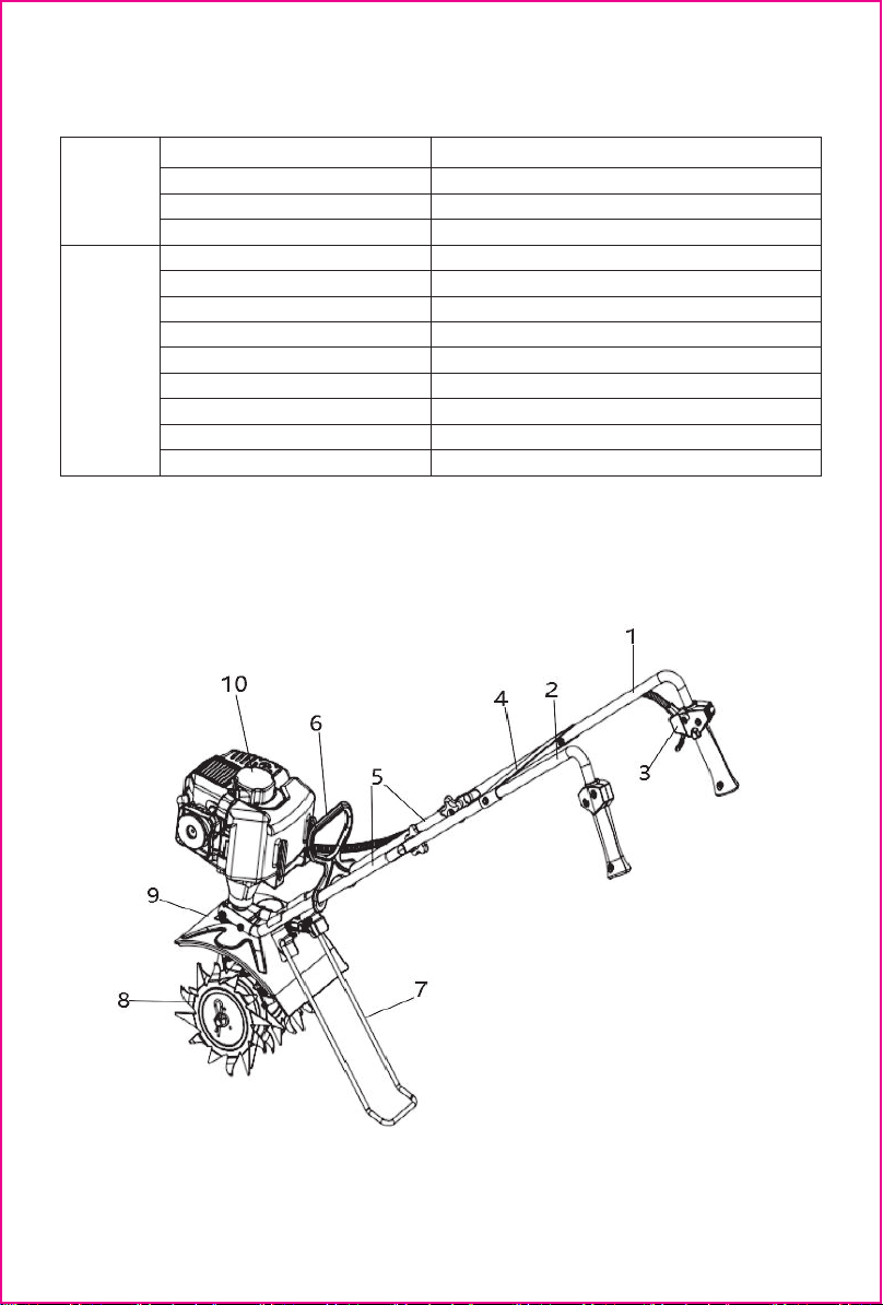
3. STRUCTURE
1. Right handle 2. Left h
Oil type 10W-30
Fuel tank capacity 650ml
Oil tank capacity 80ml
andle 3.Throttle switch assembly 4. Panel
5. Down handle 6. Handle 7. Bracket 8. Blade
9. Mud guard 10.Engine
Body
Working width
8.6 inch
Working depth 2.7 inch
Reduction ratio
44:1
Net weight 30.2lb
Engine Model
Displacement 38 cc
Method of starting Recoil starting
Max output 1.0kw/6500r/min
Fuel type Unleaded gasoline
Igniting mode CDI
4-stroke,140FA

4.Assembly of machines
Warning :The connection should be firm during installation, and it should not be loose or falling off.
4
17 Throttle handle
13 Panel
8 Right handle
12 Left handle
7 Bracket
2 M6x90 bolt
1 Saddle-shaped long gasket
4 M6x80 bolt
5 Down handle
6 Carrying handle
14 M6x30 bolt
9 Sector bolt
16 Throttle cable
3 Locknut
11 Locknut
10 Butterfly nuts
15 Fender
18 Handle grip
19 Nylon cable tie
19 Nylon cable tie
1. Connection frame assembly
A. Install the saddle-shaped long gasket 1 along the outside of the short legs of one down handle 5 ,and align the
saddle type long gasket with the down handle hole;
B. Take an M6*90 bolt 2 , pass it through the first group of holes (nearthebend), then pass the corresponding hole of
the other down handle through the installation of another saddle type long gasket, add a locknut 3 and tighten it by
hand;
C. Find the groove under the engine, then separate the two down handles and insert them from the wide side
of the groove;
D. Take an M6*80 bolt through the second hole of the down handle, add a locknut, and the ntighten it by hand.
2. Handle assembly
A. Gently press the down handle to align it with the two holes on the carrying handle 6 , then slide the handle back
and forth on the down handle, and the handle will be located 120mm-160mm above the fender 15 ;
B. Install the bracket 7 , unscrew the two bolts above the bracket, assemble the upper groove pressing plate above the
down handle (30mm-40mm at the upper end of the bending), then place the support leg under the down handle to align
it with the pressing plate hole, and then install and tighten the removed bolts;
C. Tighten the two nuts to fix the down handle and the gasoline engine;
D. Install the right handle bar 8 , align the hole of the groove of the right handle bar with the upper end hole of the down
handle, take the Sector bolt 9 M8x50 and insert it into the hole from the outside, tighten them with butterfly nuts 10 to fix
the upper and down handles;
E. Install the left handle 12 bar and repeat step C;
F. Install the panel 13 , align it with the left and right handlebar holes, and then insert the two bolts M6*30 14 into
the holes from the outside, and tighten them with lucknuts;

5. OPERATION
Ⅰ.Adding oil
4-stroke oil
Attention: 1.Please use 92 # and above pure gasoline.
2. Adding fuel must be done under the instruction of the fireproofing.
3.Never add fuel to a running engine or hot engine.
4.Fill fuel tank outdoors with extreme care.
Ⅱ. Start up
(1)Press the button of carburetor 5~6 times, until some fuel in the tube, then close the broker;
Note: if engine is in high temperature, you should put the choker on the original position.
(2) Open the accelerograph 1/3~1/2;
(3) Pull the starter smoothly, after starting the engine, open choker fully.
Note: (1). Make sure there is nothing lock the gear wheels before starting
(2).when the gear blade is running, make sure the gear blade do not come up against anything or anybody.
Ⅲ. Assignment
Strictly control the rotating speed, the free-load forward speed should be at 0.5m/sec when the rotate speed arrive at
8000~9000/min.
To be ensure the quality of rotating blade, don’t touch it to other objects, such as stone.
Ⅳ. Stopping
(1) Put the throttle lever at the idle speed, make the engine run 2~3 minutes;
(2) Turn off the stop switch.
Note: In urgent case, turn off the throttle switch, and turn off the stop switch. Keep your hands far away from rotating
blade, the gear is still turning after stopping the machine.
6.MAINTENANCE
Ⅰ.Maintenance body
(1) After the machine works for one or two hours or when stopping to add oil; you must check each screw and nut on
the machine to make sure they are not loosen
(2) Add the lube in the gear box when the machine works around 20 hours
(3) When the blade or gear damaged, please repair or replace at once.
Ⅱ.Maintenance engine
(1)maintenance spark plug
Keep the spark plug cleaning, the electrode gap should be moderate suitable to ensure the engine working well. The
correct gap should be around 0.5~0.7mm, check frequently and adjust it when the gap is too long or too short.
(2)Maintenance the air filter
Air filter surface should be cleaned often, if the cleaner element were jammed, clean the element. Clean the filter body
by gas. Drop a little motor oil on the cleaner element, not attach it back to the inside cover until the oil dry. If the sponge
is too dirty, please change a new one.
5

FIG.I: MINI TILLER EXPLODED PICTURE AND PARTS LIST
6

No Part name Qty No Part name Qty No Part name Qty
1 Blade A 1 14 Shaft 1 28 Sector bolt M8x50 2
2 Blade B 1 15 Mud guard bracket 1 29 Down handle 2
3 Allen screw M6x25 2 16
Mud guard
1 30 Plum knob 2
4 Allen screw M6*14 1 17 External hexagon flange bolt
M6x14
4 31 Throttle switch assembly 1
5 Gear case 1 18 Down handle pressing plate 2 32 External hexagon bolt
M6X30
2
6 Blade C 1 19 External hexagon flange nut
M6
6 33 Right handle 1
7Blade D 1 20 External hexagon flange bolt
M6x32
4 34 Panel 1
8 R-shaped pin ϕ3.5X70 2 21 External hexagon flange bolt
M6x30
2 35 Left handlebar cover 1
9 R-shaped pin ϕ1.5X32 2 22 Allen screw M5*12 1 36 Left handle 1
10 Compression spring
15x10.5x25
2 23 Clutch housing assembly 1
11 Bracket 1 24 Engine 1
12 Washer ϕ10X20x2 1 25 Bracket support 1
13 External hexagon bolt
M8X80
1 26
Upper groove pressing
plate
2
13-1 External hexagon bolt
M8X90
1 27 Handle 1
7


Table of contents


