UF V (E2+E2.1) 03/2013 page 8/112
Contents
EC – declaration of conformity ......................................................................................................................2
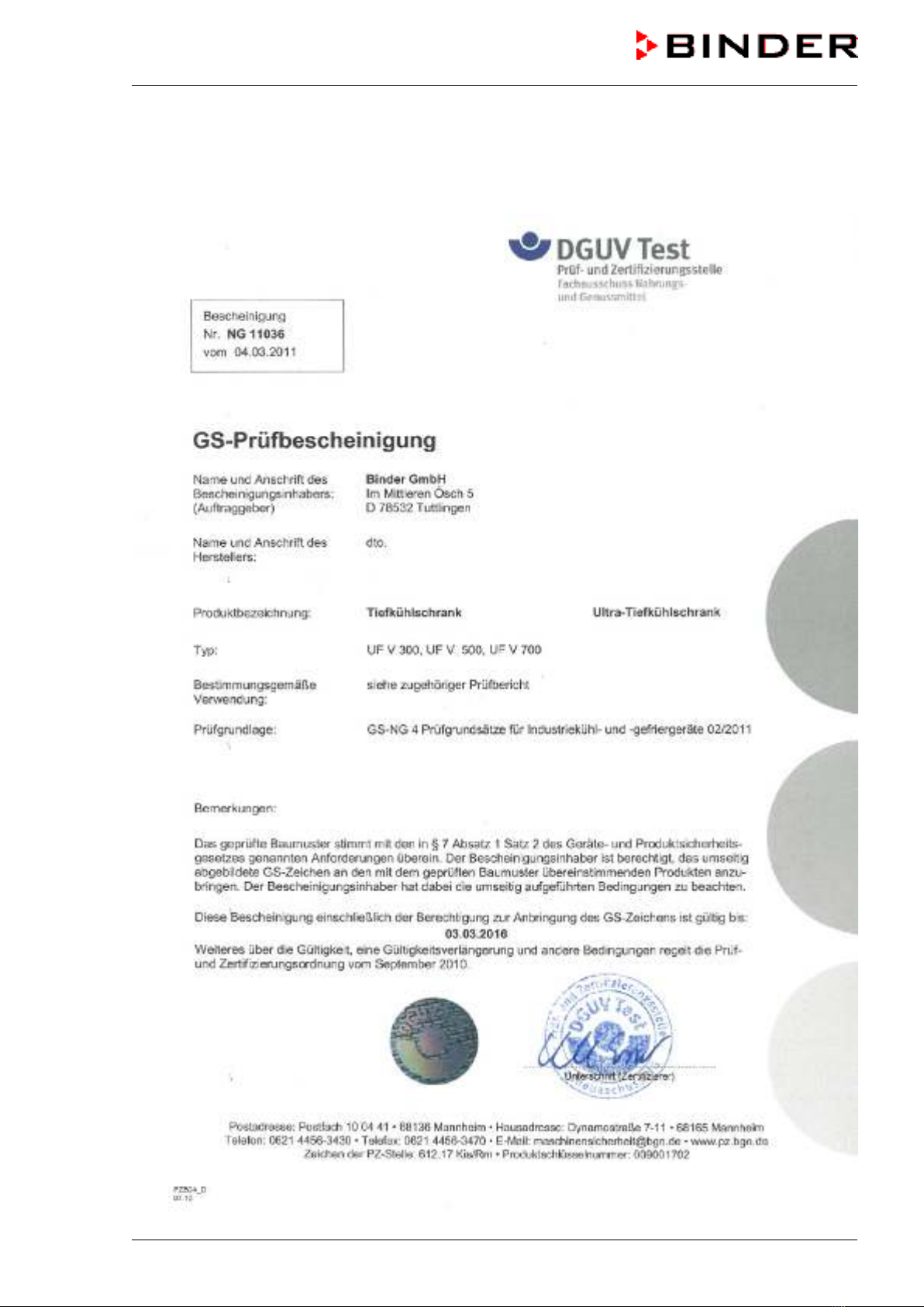
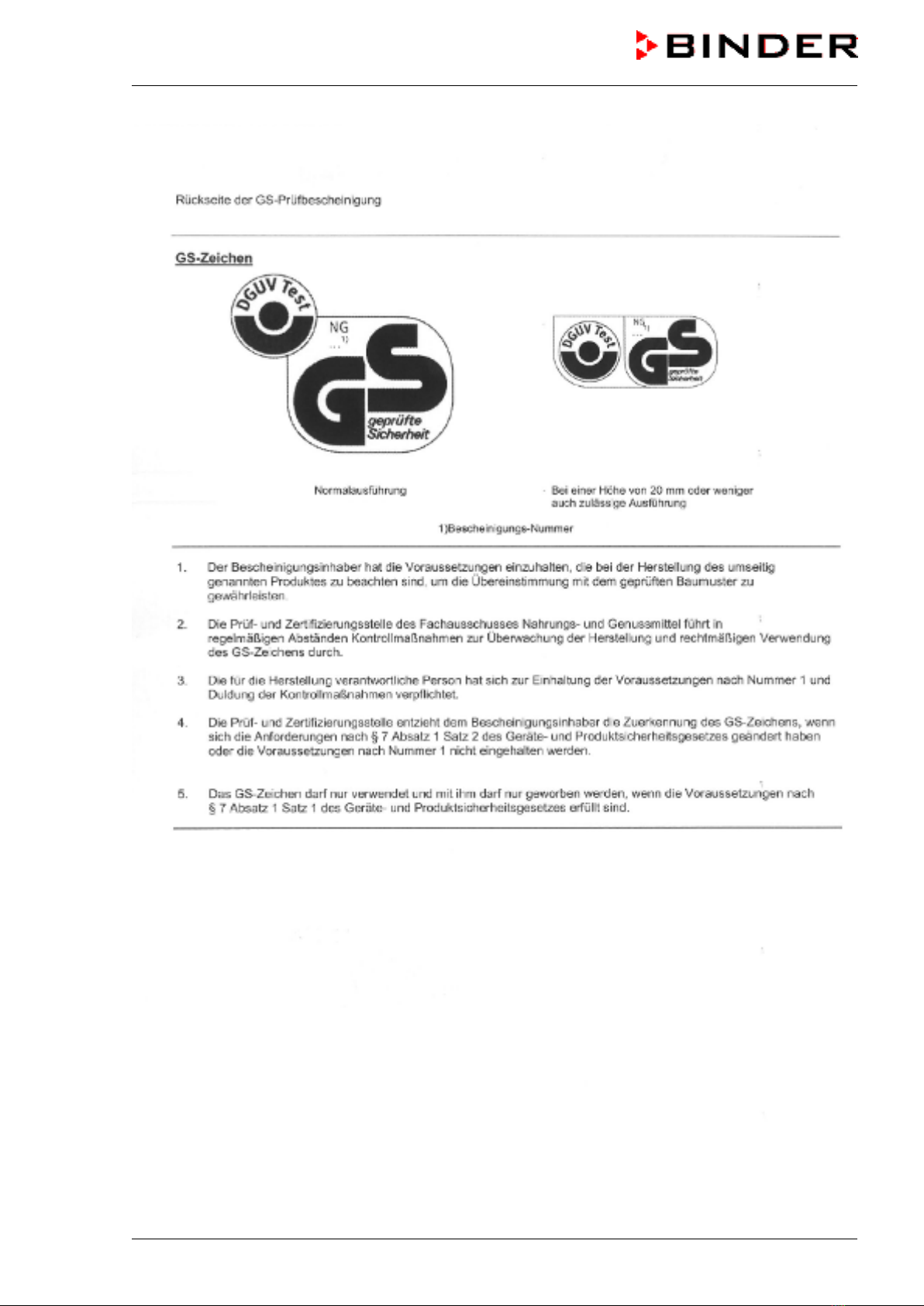
Certificate for the GS mark of conformity of the “Deutsche Gesetzliche Unfallversicherung e.V.“
(German Social Accident Insurance) DGUV.......................................................................................5
Product registration .......................................................................................................................................7
1. SAFETY................................................................................................................ 11
1.1 Legal considerations .........................................................................................................................11
1.2 Structure of the safety instructions....................................................................................................11
1.2.1 Signal word panel ........................................................................................................................11
1.2.2 Safety alert symbol ......................................................................................................................12
1.2.3 Pictograms ...................................................................................................................................12
1.2.4 Word message panel structure....................................................................................................13
1.3 Localization / position of safety labels at the unit..............................................................................13
1.4 Type plate .........................................................................................................................................14
1.5 General safety instructions on installing and operating the UF V freezer ........................................15
1.6 Intended use .....................................................................................................................................17
1.7 Operating instructions .......................................................................................................................17
1.8 Measures to prevent accidents.........................................................................................................18
2. UNIT DESCRIPTION ............................................................................................ 19
2.1 Unit overview.....................................................................................................................................21
2.2 Housing of the automatic door mechanism with operator panel ......................................................23
2.3 Key switch (main power switch)........................................................................................................24
2.4 RP1 controller ...................................................................................................................................25
2.5 Connection panel on the unit rear.....................................................................................................26
2.6 Unit doors..........................................................................................................................................27
2.6.1 Outer door....................................................................................................................................27
2.6.2 Compartment doors .....................................................................................................................27
2.6.3 Emergency release of the outer door ..........................................................................................27
2.7 Drain well for condensate during defrosting (option)........................................................................29
3. COMPLETENESS OF DELIVERY, TRANSPORTATION, STORAGE, AND
INSTALLATION.................................................................................................... 30
3.1 Unpacking, and checking equipment and completeness of delivery................................................30
3.2 Guidelines for safe lifting and transportation ....................................................................................31
3.2.1 Moving the freezer inside a building ............................................................................................31
3.2.2 Transport outside a building ........................................................................................................32
3.3 Storage..............................................................................................................................................33
3.4 Location of installation and ambient conditions ................................................................................33
3.5 Adjusting the vertically adjustable castors ........................................................................................34
4. INSTALLATION AND CONNECTIONS................................................................ 36
4.1 Operating instructions .......................................................................................................................36
4.2 Spacers for rear wall distance...........................................................................................................36
4.3 Fixing to achieve earthquake safety (optional) .................................................................................37
4.4 10 mm access port prepared to be finalized by the user (UF V (E2.1), UF V-UL (E2.1)) ................38
4.5 Adjustable shelves ............................................................................................................................39
4.6 Electrical connection .........................................................................................................................41
4.7 Advanced voltage booster (regular with UF V UL, option for UF V))................................................41
5. START UP............................................................................................................ 42
5.1 Preset factory parameters.................................................................................................................42
5.2 Operating the automatic door mechanism........................................................................................42
5.3 Door locking with key (option for UF V UL).......................................................................................43