Binder UF V Series User manual

Version 04/2023 Art. No. 7001-0374
Operating Manual
Translation of the Original Operating Manual
UF V (E3)
Ultra Low Temperature Freezers
with RD4 Controller
Model
Model version
Art. No.
Voltage
UF V
UF V 350
UFV350-230V
9020-0453, 9120-0453
230 V
UF V 500
UFV500-230V
9020-0347, 9120-0347
230 V
UF V 700
UFV700-230V
9020-0348, 9120-0348
230 V
UF V-UL
UF V 350
UFV350UL-120V
9020-0454, 9120-0454
120 V
UF V 350
UFV350UL-240V
9020-0455, 9120-0455
208-240 V
UF V 500-UL
UFV500UL-120V
9020-0351, 9120-0351
120 V
UF V 500-UL
UFV500UL-240V
9020-0353, 9120-0353
208-240 V
UF V 700-UL
UFV700UL-120V
9020-0352, 9120-0352
120 V
UF V 700-UL
UFV700UL-240V
9020-0354, 9120-0354
208-240 V
UF V with water cooling
UF V 500
UFV500-230V-H2O
9020-0349, 9120-0349
230 V
UF V 700
UFV700-230V-H2O
9020-0350, 9120-0350
230 V
BINDER GmbH
Address: Post office box 102, 78502 Tuttlingen, Germany Phone: +49 7462 2005 0
Fax: +49 7462 2005 100 Internet: http://www.binder-world.com
Service Hotline: +49 7462 2005 555
Service Fax: +49 7462 2005 93 555
Service Hotline USA: +1 866 885 9794 or +1 631 224 4340 x3
Service Hotline Asia Pacific: +852 390 705 04 or +852 390 705 03

UF V (E3) 04/2023 Page 2/123
Contents
1. SAFETY.................................................................................................................. 6
1.1 Personnel Qualification .......................................................................................................................6
1.2 Operating manual................................................................................................................................6
1.3 Legal considerations ...........................................................................................................................6
1.3.1 Intellectual property ...................................................................................................................7
1.4 Structure of the safety instructions......................................................................................................7
1.4.1 Signal word panel......................................................................................................................7
1.4.2 Safety alert symbol....................................................................................................................8
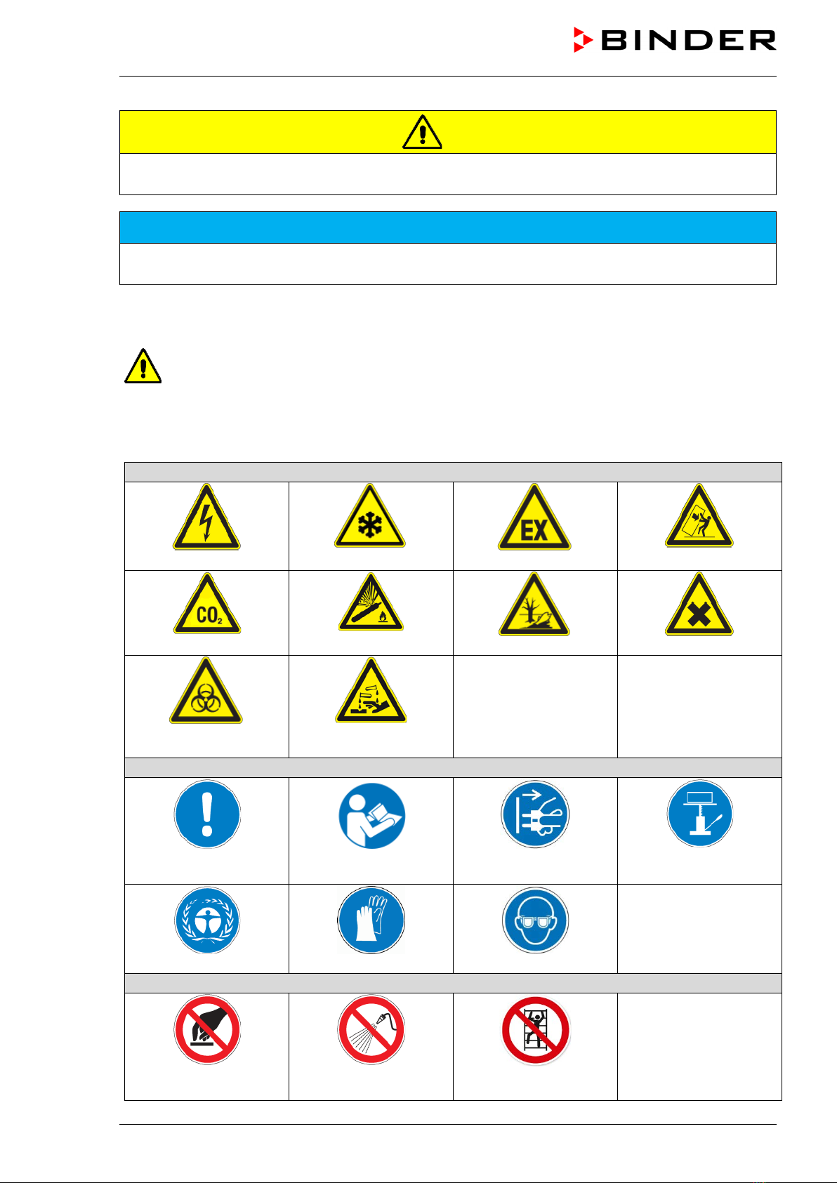
1.4.3 Pictograms.................................................................................................................................8
1.4.4 Word message panel structure .................................................................................................9
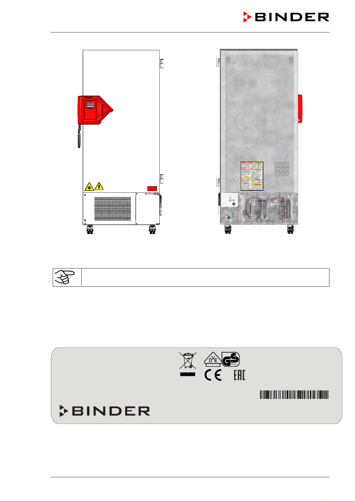
1.5 Localization / position of safety labels at the chamber .......................................................................9
1.6 Type plate..........................................................................................................................................10
1.7 UKCA Label ......................................................................................................................................12
1.8 General safety instructions on installing and operating the chamber ...............................................12
1.9 Intended use .....................................................................................................................................14
1.10 Foreseeable Misuse..........................................................................................................................16
1.11 Residual Risks ..................................................................................................................................16
1.12 Operating instructions .......................................................................................................................18
1.13 Measures to prevent accidents .........................................................................................................18
2. CHAMBER DESCRIPTION .................................................................................. 19
2.1 Chamber overview ............................................................................................................................21
2.2 Door lock and controller housing ......................................................................................................23
2.2.1 Operating the NumPad (option “Door access system” for UF V 500 and UF V 700)..............24
2.2.2 Operating the electromechanical door locking (option “Door access system” for UF V 500 and
UF V 700)................................................................................................................................24
2.3 Main power switch.............................................................................................................................25
2.4 Chamber rear ....................................................................................................................................26
2.5 Doors.................................................................................................................................................27
2.5.1 Outer door ...............................................................................................................................27
2.5.2 Compartment doors.................................................................................................................27
2.5.3 Operating the door lock (option “Lockable door handle”)........................................................28
2.6 Drain well for condensate during defrosting (option) ........................................................................28
3. COMPLETENESS OF DELIVERY, TRANSPORTATION, STORAGE, AND
INSTALLATION.................................................................................................... 29
3.1 Unpacking, and checking equipment and completeness of delivery ................................................29
3.2 Guidelines for safe lifting and transportation.....................................................................................30
3.2.1 Moving the freezer inside a building........................................................................................30
3.2.2 Transport outside a building ....................................................................................................31
3.3 Storage..............................................................................................................................................32
3.4 Location of installation and ambient conditions ................................................................................32
4. INSTALLATION AND CONNECTIONS ............................................................... 34
4.1 Operating instructions .......................................................................................................................34
4.2 Spacers for rear wall distance...........................................................................................................34
4.3 Support feet (UF V 350 only) ............................................................................................................34
4.4 Adjustable shelves ............................................................................................................................35
4.5 Connections of cooling water for chambers with water cooling ........................................................37
4.5.1 Connection of cooling water outlet for water cooling...............................................................37
4.5.2 Connection of cooling water inlet for water cooling.................................................................38
4.5.3 Connection kit for cooling water ..............................................................................................38
4.6 Electrical connection .........................................................................................................................40
4.7 Advanced voltage booster (option) ...................................................................................................40

UF V (E3) 04/2023 Page 3/123
5. FUNCTIONAL OVERVIEW OF THE RD4 CHAMBER CONTROLLER ............... 41
5.1 Menu structure of the controller and access levels...........................................................................42
6. START UP............................................................................................................ 43
6.1 Preset factory parameters.................................................................................................................43
6.2 Behavior after turning on the chamber..............................................................................................43
7. TEMPERATURE SET-POINT ENTRY ................................................................. 44
8. PLACING SAMPLES IN STORAGE IN THE FREEZER...................................... 45
9. SETTING SPECIAL CONTROLLER FUNCTIONS .............................................. 46
10. PASSWORD......................................................................................................... 47
10.1 Password request .............................................................................................................................47
10.2 Assign and modify a password .........................................................................................................47
10.2.1 Assign and modify the User password ....................................................................................48
10.2.2 Assign and modify the Admin password .................................................................................48
10.3 Performance during and after power failure and shut down .............................................................49
11. SAFETY CONTROLLER (TEMPERATURE SAFETY DEVICE).......................... 49
11.1 Setting the safety controller mode ....................................................................................................50
11.2 Setting the safety controller value.....................................................................................................50
11.3 Message and measures in the state of alarm...................................................................................51
11.4 Function check ..................................................................................................................................51
12. GENERAL CONTROLLER SETTINGS................................................................ 52
12.1 Selecting the controller’s menu language .........................................................................................52
12.2 Selecting the temperature unit ..........................................................................................................52
12.3 Setting the current date.....................................................................................................................53
12.4 Setting the current time .....................................................................................................................54
12.5 Function “Language selection at restart” ..........................................................................................54
12.6 Setting the chamber address ............................................................................................................55
12.7 Display brightness.............................................................................................................................55
13. TOLERANCE RANGE AND ALARM DELAY SETTINGS ................................... 56
13.1 Setting the delay time for door open alarm .......................................................................................56
13.2 Setting the delay time for tolerance range alarm ..............................................................................56
13.3 Setting the temperature tolerance range ..........................................................................................57
14. ALARM FUNCTIONS ........................................................................................... 58
14.1 Alarm messages ...............................................................................................................................58
14.2 Information messages.......................................................................................................................60
14.3 Activating / deactivating the audible alarm (alarm buzzer) ...............................................................60
14.4 Required actions in case of an alarm................................................................................................61
14.4.1 Safety controller temperature alarm ........................................................................................61
14.4.2 Temperature tolerance range alarm (too high and too low temperature) ...............................61
14.4.3 Door open alarm......................................................................................................................62
14.4.4 Power failure alarm (chamber with option “battery-buffered alarm system”) ..........................62
14.4.5 Messages on the battery management system (chamber with option “battery-buffered alarm
system”) ..................................................................................................................................63
14.4.6 Messages referring to temperature sensor failure ..................................................................64
14.4.7 Messages referring to CO2emergency cooling (option CO2emergency cooling) ..................65
14.5 Zero-voltage relay alarm output ........................................................................................................66
15. ETHERNET NETWORK SETTINGS .................................................................... 67
15.1 Showing the network settings ...........................................................................................................67
15.1.1 Showing the chamber‘s MAC address ....................................................................................67
15.1.2 Showing the IP address...........................................................................................................67

UF V (E3) 04/2023 Page 4/123
15.1.3 Showing the subnet mask .......................................................................................................68
15.1.4 Showing the standard gateway ...............................................................................................68
15.1.5 Showing the DNS server address ...........................................................................................68
15.1.6 Showing the DNS chamber name ...........................................................................................69
15.2 Changing the configuration of the network settings ..........................................................................69
15.2.1 Selecting the type of IP address assignment (automatic / manual) ........................................69
15.2.2 Selecting the type of assignment of the DNS server address (automatic / manual)...............70
15.2.3 Assigning the IP address.........................................................................................................70
15.2.4 Setting the subnet mask ..........................................................................................................71
15.2.5 Setting the standard gateway..................................................................................................71
15.2.6 Assigning the DNS server address .........................................................................................72
16. ACCESS CODES (OPTION “DOOR ACCESS SYSTEM” FOR UF V 500 AND UF
V 700) ................................................................................................................... 72
16.1 Assigning the access codes..............................................................................................................72
16.2 Opening the chamber door with the access code.............................................................................73
17. DATA RECORDER .............................................................................................. 74
17.1 Recorded data...................................................................................................................................74
17.2 Storage capacity ...............................................................................................................................75
17.3 Setting the storage rate for the “DL1” recorder data.........................................................................75
17.4 Deleting the data recorder.................................................................................................................75
18. USB-MENU: DATA TRANSFER VIA USB INTERFACE ..................................... 76
18.1 Connecting the USB stick .................................................................................................................76
18.2 Import function ..................................................................................................................................76
18.3 Export functions ................................................................................................................................77
18.4 Ongoing data transfer .......................................................................................................................77
18.5 Error during data transmission..........................................................................................................78
18.6 Removing the USB stick ...................................................................................................................78
19. BATTERY MANAGEMENT SYSTEM (OPTION “BATTERY-BUFFERED ALARM
SYSTEM”) ............................................................................................................ 78
19.1 Battery operation...............................................................................................................................78
19.2 Charging voltage ...............................................................................................................................79
20. SETTING AND ACTIVATING THE SERVICE SETPOINT ................................... 79
20.1 Setting the service setpoint ...............................................................................................................79
20.2 Activating the service setpoint...........................................................................................................80
21. CO2EMERGENCY COOLING (OPTION) ............................................................ 81
21.1 Connecting and exchanging the pressurized CO2cylinder...............................................................82
21.2 Operating the CO2emergency cooling system.................................................................................84
21.3 Settings on the chamber controller ...................................................................................................85
21.3.1 Setting the CO2emergency cooling temperature setpoint ......................................................85
21.3.2 Activating the CO2emergency cooling....................................................................................86
21.3.3 Test run of the CO2emergency cooling ..................................................................................87
22. DATA MONITORING AND RECORDING ............................................................ 88
22.1 Ethernet interface..............................................................................................................................88
22.2 APT-COM™ 4 Multi Management Software (option)........................................................................88
22.3 Analog output for temperature (option) .............................................................................................88
23. CHAMBER INVENTORY: STORAGE RACK SYSTEMS AND CRYO BOXES
(OPTION).............................................................................................................. 89
23.1 Storage rack systems with or without cryo boxes.............................................................................89
23.2 Cryo boxes ........................................................................................................................................89

UF V (E3) 04/2023 Page 5/123
24. CLEANING AND DECONTAMINATION .............................................................. 90
24.1 Cleaning ............................................................................................................................................90
24.2 Decontamination / chemical disinfection...........................................................................................92
25. MAINTENANCE AND SERVICE, SERVICE, TROUBLESHOOTING, REPAIR,
TESTING .............................................................................................................. 93
25.1 General information, personnel qualification.....................................................................................93
25.2 Maintenance work by the customer ..................................................................................................94
25.2.1 Checking and cleaning / replacing the condenser air filter......................................................94
25.2.2 Cleaning the condenser...........................................................................................................95
25.2.3 De-icing and defrosting............................................................................................................95
25.2.4 Maintenance of the door lock ..................................................................................................96
25.3 Simple troubleshooting......................................................................................................................96
25.4 Maintenance intervals, service..........................................................................................................98
25.5 Service Reminder..............................................................................................................................99
25.6 Sending the chamber back to BINDER GmbH .................................................................................99
26. DISPOSAL.......................................................................................................... 100
26.1 Disposal of the transport packing....................................................................................................100
26.2 Decommissioning............................................................................................................................100
26.3 Disposal of the chamber in the Federal Republic of Germany .......................................................101
26.4 Disposal of the chamber in the member states of the EU except for the Federal Republic of
Germany..........................................................................................................................................102
26.5 Disposal of the chamber in non-member states of the EU .............................................................103
27. TECHNICAL DESCRIPTION.............................................................................. 104
27.1 Factory calibration and adjustment .................................................................................................104
27.2 Over current protection ...................................................................................................................104
27.3 Technical data.................................................................................................................................104
27.4 Equipment and options (extract) .....................................................................................................107
27.5 Optional equipment, accessories and spare parts (extract) ...........................................................108
27.6 Dimensions of UF V 350 (E3) .........................................................................................................110
27.7 Dimensions of UF V 500 (E3) .........................................................................................................111
27.8 Dimensions of UF V 700 (E3) .........................................................................................................112
28. CERTIFICATES AND DECLARATIONS OF CONFORMITY............................. 113
28.1 EU Declaration of Conformity..........................................................................................................113
28.2 UKCA Declaration of Conformity ....................................................................................................115
28.3Certificate for the GS mark of conformity of the “VDE Prüf- und Zertifizierungsinstitut” (Testing and
Certification Institute of the Association for Electrical, Electronic and Information Technologies) .116
28.4 Certificate of UL Compliance from Underwriters Laboratories Inc.®...............................................117
29. CONTAMINATION CLEARANCE CERTIFICATE ............................................. 118
29.1 For chambers located outside the USA and Canada .....................................................................118
29.2 For chambers in the USA and Canada ...........................................................................................121

UF V (E3) 04/2023 Page 6/123
Dear Customer,
For the correct operation of the ultra-low temperature freezer UF V, it is important that you read this oper-
ating manual completely and carefully and observe all instructions as indicated. Failure to read, understand
and follow the instructions may result in personal injury. It can also lead to damage to the chamber and/or
poor equipment performance.
1. Safety
1.1 Personnel Qualification
The chamber must only be installed, tested, and started up by personnel qualified for assembly, startup,
and operation of the chamber. Qualified personnel are persons whose professional education, knowledge,
experience and knowledge of relevant standards allow them to assess, carry out, and identify any potential
hazards in the work assigned to them. They must have been trained and instructed, and be authorized, to
work on the chamber.
The chamber should only be operated by laboratory personnel especially trained for this purpose and fa-
miliar with all precautionary measures required for working in a laboratory. Observe the national regulations
on minimum age of laboratory personnel.
1.2 Operating manual
This operating manual is part of the components of delivery. Always keep it handy for reference in the
vicinity of the chamber. If selling the unit, hand over the operating manual to the purchaser.
To avoid injuries and damage observe the safety instructions of the operating manual. Failure to follow
instructions and safety precautions can lead to significant risks.
DANGER
Dangers due to failure to observe the instructions and safety precautions.
Serious injuries and chamber damage. Risk of death.
Observe the safety instructions in this Operating Manual.
Follow the operating procedures in this Operating Manual.
Carefully read the complete operating instructions of the chamber prior to installing and
using the chamber.
Keep the operating manual for future reference
Make sure that all persons who use the chamber and its associated work equipment have
read and understood the Operating Manual.
This Operating Manual is supplemented and updated as needed. Always use the most recent version of
the Operating Manual. When in doubt, call the BINDER Service Hotline for information on the up-to-date-
ness and validity of this Operating Manual.
1.3 Legal considerations
This operating manual is for informational purposes only. It contains information for correct and safe in-
stalling, start-up, operation, decommissioning, cleaning and maintenance of the product. Note: the contents
and the product described are subject to change without notice.

UF V (E3) 04/2023 Page 7/123
Understanding and observing the instructions in this operating manual are prerequisites for hazard-free use
and safety during operation and maintenance. Images are to provide basic understanding. They may devi-
ate from the actual version of the chamber. The actual scope of delivery can, due to optional or special
design, or due to recent technical changes, deviate from the information and illustrations in these instruc-
tions this operating manual. In no event shall BINDER be held liable for any damages, direct or incidental
arising out of or related to the use of this manual.
This operating manual cannot cover all conceivable applications. If you would like additional information,
or if special problems arise that are not sufficiently addressed in this manual, please ask your dealer or
contact us directly, e.g. by phone at the number located on page one of this manual
Furthermore, we emphasize that the contents of this operating manual are not part of an earlier or existing
agreement, description, or legal relationship, nor do they modify such a relationship. All obligations on the
part of BINDER derive from the respective purchase contract, which also contains the entire and exclusively
valid statement of warranty administration and the general terms and conditions, as well as the legal regu-
lations valid at the time the contract is concluded. The statements in this manual neither augment nor restrict
the contractual warranty provisions.
1.3.1 Intellectual property
This operating manual is protected by copyright. Any unauthorized copying or disclosure to third
parties is strictly prohibited. We reserve the right to take legal action and, if necessary, to assert
claims for damages in the event of infringement.
Trademark Information: All BINDER trademarks relating to products or service, as well as trade names,
logos and product names used on the website, products and documents of BINDER company are trade-
marks or registered trademarks of BINDER company (including BINDER GmbH, BINDER Inc.) in the U.S.
and other countries and communities of states. This includes word marks, position marks, word/figurative
marks, design configurations, figurative marks, and design patents.
Patent Information: BINDER products, categories of products, and accessories may be covered by one
or more patents and/or utility models in the U.S. and other countries and communities of states. This infor-
mation is provided to satisfy the virtual patent marking provisions of various jurisdictions, in particular it is
intended to serve as notice under 35 U.S.C. § 287(a). Products and services listed on the BINDER website
may be sold individually or as part of a combination product. Additional patent applications may also be
pending in the U.S. and other countries and communities of states.
Please visit www.binder-world.com for more information.
1.4 Structure of the safety instructions
In this operating manual, the following safety definitions and symbols indicate dangerous situations in ac-
cordance with the standards ISO 3864-2 and ANSI Z535.6.
1.4.1 Signal word panel
Depending on the probability of serious consequences, potential dangers are identified with a signal word,
the corresponding safety color, and if appropriate, the safety alert symbol.
DANGER
Indicates an imminently hazardous situation that, if not avoided, will result in death or serious (irreversi-
ble) injury.
WARNING
Indicates a potentially hazardous situation which, if not avoided, could result in death or serious
(irreversible) injury

UF V (E3) 04/2023 Page 8/123
CAUTION
Indicates a potentially hazardous situation which, if not avoided, may result in moderate or minor
(reversible) injury
NOTICE
Indicates a potentially hazardous situation which, if not avoided, may result in damage to the product
and/or its functions or of a property in its proximity.
1.4.2 Safety alert symbol
Use of the safety alert symbol indicates a risk of injury.
Observe all measures that are marked with the safety alert symbol in order to avoid death or
injury.
1.4.3 Pictograms
Warning signs
Electrical hazard
Very cold surface
Explosive atmosphere
Stability hazard
CO2suffocation hazard
Gas cylinders
Pollution Hazard
Harmful substances
Biohazard
Risk of corrosion and /
or chemical burns
Mandatory action signs
Mandatory regulation
Read operating
instructions
Disconnect the power
plug
Lift with mechanical
assistance
Environment protection
Wear protective gloves
Wear safety goggles
Prohibition signs
Do NOT touch
Do NOT spray with
water
Do NOT climb

UF V (E3) 04/2023 Page 9/123
Information to be observed in order to ensure optimum function of the product.
1.4.4 Word message panel structure
Type / cause of hazard.
Possible consequences.
∅Instruction on how to avoid the hazard: prohibition
Instruction on how to avoid the hazard: mandatory action
Observe all other notes and information not necessarily emphasized in the same way, in order to avoid
disruptions that could result in direct or indirect injury or property damage.
1.5 Localization / position of safety labels at the chamber
The following labels are located on the chamber:
Pictograms (Warning signs) Information
Very cold surface: Risk of freezing
Energy Star Symbol
(only UL chambers)
Risk of injury.
Observe the safety instructions in the
operating manual.
Flammable refrigerants
(only UL chambers)
Service label

UF V (E3) 04/2023 Page 10/123
UF V with optional CO2emergency cooling UF V-UL, rear view
Figure 1: Position of labels on the ultra-low temperature freezer UF V
Keep safety labels complete and legible.
Replace safety labels that are no longer legible. Contact BINDER Service for these replacements.
1.6 Type plate
The type plate sticks to the left side of the chamber, bottom right-hand.
Figure 2: UF V type plate (example UF V 500 (E3) standard chamber)
Nominal temp.
-90 °C
1,60 kW / 9,0 A
Max. operating pressure 28 bar
-130 °F
230 V / 50 Hz
Stage 1: R290– 0,150 kg
IP protection
20
Stage 2: R170 – 0,150 kg
Safety device
DIN 12880
1 N ~
Contains hydrocarbon gases
Class
3.1
Art. No.
9020-0347
Project No.
Built
2022
ULT Freezer UF V 500
BINDER GmbH
Im Mittleren Ösch 5
78532 Tuttlingen / Germany
www.binder-world.com
E3
Serial No. 00000000000000
Made in Germany

UF V (E3) 04/2023 Page 11/123
Figure 3: UF V-UL type plate (example UF V 500-UL (E3) standard chamber)
Indications of the type plate (example)
Indication
Information
BINDER
Manufacturer: BINDER GmbH
ULT Freezer
Device name: ultra-low temperature freezer
UF V 500
Model designation
Serial No.
000000000000
Serial no. of the chamber
Built
2022
Year of construction
Nominal temperature
-90 °C
-130 °F
Nominal temperature
IP protection
20
IP type of protection acc. to standard EN 60529
Temp. safety device
DIN 12880
Temperature safety device acc. to standard DIN 12880
Class
---
Class of temperature safety device
Art. No.
9020-0347
Art. no. of the chamber
Project No.
---
Optional: Special application acc. to project no.
1,60 kW
Nominal power
9,0 A
Nominal current
230 V / 50 Hz
Nominal voltage +/- 10%
at the indicated power frequency
1 N ~
Current type
Max. operating pressure 28 bar
Max operating pressure in the refrigerating system
Stage 1: R290 – 0,15 kg
Cooling 1
st
stage: Refrigerant type, filling weight
Stage 2: R170 – 0,15 kg
Cooling 2nd stage: Refrigerant type, filling weight
Contains hydrocarbon gases
Symbols on the type plate
Symbol Applies to Information
All models CE conformity marking
All models
Electrical and electronic equipment manufactured / placed on
the market in the EU after 13 August 2005 and to be disposed
of in a separate collection according to directive 2012/19/EU on
waste electrical and electronic equipment (WEEE).
Not valid for UL
chambers. Not
valid for UF V 350
The chamber is certified according to Customs Union Technical
Regulation (CU TR) for the Eurasian Economic Union (Russia,
Belarus, Armenia, Kazakhstan Kyrgyzstan).
Nominal temp.
-90 °C
1,60 kW / 7,7 A
Max. operating pressure 28 bar
-130 °F
208-230 V / 60 Hz
Stage 1: R290– 0,150 kg
IP protection
20
Stage 2: R170 – 0,150 kg
Safety device
DIN 12880
2 ~
Contains hydrocarbon gases
Class
3.1
Art. No.
9020-0347
Project No.
Built
2022
ULT Freezer
UF V 500-UL
BINDER GmbH
Im Mittleren Ösch 5
78532 Tuttlingen / Germany
www.binder-world.com
E3
Serial No. 00000000000000
Made in Germany

UF V (E3) 04/2023 Page 12/123
Symbol Applies to Information
Not valid for UL
chambers. Not
valid for UF V 350
GS mark of conformity of the “VDE Prüf- und Zertifizierungsin-
stitut” (Testing and Certification Institute of the Association for
Electrical, Electronic and Information Technologies)
Note: Chambers equipped with the optional CO2emergency
cooling do not bear the GS mark.
UL chambers only
The chamber is certified by Underwriters Laboratories Inc.®ac-
cording to the following standards:
•UL 61010-1, 3rd Edition, 2012-05, Rev. 2016-04
•UL 61010-2-011, 1st Edition, 2017-01
•CAN/CSA-C22.2 No. 61010-1, 3rd Edition, 2012-
05, Rev.
2016-04
Note: Chambers equipped with the optional CO2emergency
cooling do not bear the cUL test mark.
1.7 UKCA Label
The sticker with UKCA Authorised Representative details sticks next to the type plate to the left side of the
chamber, bottom right-hand.
Figure 4: UKCA Label
Symbol on the sticker
Symbol Applies to Information
All models except
UL models UKCA conformity marking
1.8 General safety instructions on installing and operating the chamber
With regard to operating the chamber and to the installation location, please observe the local and national
regulations relevant for your country (for Germany: DGUV guidelines 213-850 on safe working in laborato-
ries, issued by the employers’ liability insurance association).
BINDER GmbH is only responsible for the safety features of the chamber provided skilled electricians or
qualified personnel authorized by BINDER perform all maintenance and repair, and if components relating
to chamber safety are replaced in the event of failure with original spare parts.
To operate the chamber, use only original BINDER accessories or accessories from third-party suppliers
authorized by BINDER. The user is responsible for any risk caused by using unauthorized accessories.
NOTICE
Danger of overheating due to lack of ventilation.
Damage to the chamber.
∅Do NOT install the chamber in unventilated recesses.
Ensure sufficient ventilation for dispersal of the heat.
Observe the prescribed minimum distances when installing the chamber (chap. 3.4)

UF V (E3) 04/2023 Page 13/123
NOTICE
Danger to the environment by leakage of refrigerant in the event of a chamber de-
fect.
Alteration of the environment.
Ensure sufficient ventilation of the installation site.
Do not operate the chamber in hazardous locations.
DANGER
Danger of explosion due to combustible dusts or explosive mixtures in the vicinity
of the chamber.
Serious injury or death from burns and / or explosion pressure.
∅Do NOT operate the chamber in potentially explosive areas.
KEEP combustible dust or air-solvent mixtures AWAY from the chamber.
The chamber does not dispose of any measures of explosion protection.
DANGER
Danger of explosion due to introduction of flammable or explosive substances in
the chamber.
Serious injury or death from burns and / or explosion pressure.
∅Do NOT introduce any substance into the chamber which is combustible or explosive at
working temperature.
∅Do NOT introduce any combustible dust or air-solvent mixture in the inner chamber.
Any solvent contained in the charging material must not be explosive or inflammable. I.e., irrespective of
the solvent concentration in the steam room, NO explosive mixture with air must form. The temperature
inside the chamber must lie below the flash point or below the sublimation point of the charging material.
Familiarize yourself with the physical and chemical properties of the charging material.
Familiarize yourself with any potential health risks caused by the charging material. Take adequate
measures to exclude any risk prior to putting the chamber into operation.
WARNING
Danger of intoxication and infection through contamination of the chamber with
toxic, infectious or radioactive substances.
Damages to health.
Protect the interior of the chamber against contamination by toxic, infectious or radioac-
tive substances.
Take appropriate measures when bringing in or taking out toxic, infectious or radioac-
tive substances.
DANGER
Electrical hazard by water entering the chamber.
Deadly electric shock.
∅The chamber must NOT become wet during operation, cleaning, or maintenance.
∅Do NOT install the chamber in damp areas or in puddles.
Set up the chamber in a splash-proof manner.
The chambers were produced in accordance with VDE regulations and were routinely tested in accordance
to VDE 0411-1 (IEC 61010-1).

UF V (E3) 04/2023 Page 14/123
The inner surfaces become very cold during operation.
CAUTION
Danger of injury by freezing on when touching cold chamber parts during or after
operation.
Local frostbite.
∅Do NOT directly touch the inner surfaces or the charging material during operation.
∅AVOID skin contact with the inner surfaces and accessory equipment.
Wear protective gloves when opening the inner doors and during manipulation.
WARNING
Danger of injury and damages by the chamber tipping over or breakaway of the pro-
truding lower housing cover.
Injuries and damage to the chamber and the charging material
∅Do NOT climb on the lower housing cover.
∅Do NOT load the lower housing cover with heavy objects while the chamber door is
open.
1.9 Intended use
Following the instructions in this operating manual and conducting regular maintenance
work (chap. 24) are part of the intended use.
Any use of the chambers that does not comply with the requirements specified in this Operating
Manual shall be considered improper use.
Other applications than those described in this chapter are not approved.
Use
Ultra-low temperature freezers UF V are technical equipment and intended solely for use at work. They are
suitable are designed for safe storage of varied materials at temperatures up to –90 °C / -130 °F, especially
for long-term storage of biological, medical, and chemical samples at constant low temperature. They are
suitable for the domains Pharmacy, Medicine, Life Sciences, plastic industry, electronic components, food
etc.
Freezers are designed for storage of harmless materials.
Requirements for the chamber load
The charging material shall not contain any corrosive ingredients that may damage the machine compo-
nents made of stainless steel. Such ingredients include in particular acids and halides. Any corrosive dam-
age caused by such ingredients is excluded from liability by BINDER GmbH.
None of the components of the charging material must be able to form an explosive mixture with air. Any
component of the charging material must NOT be able to release toxic gases.

UF V (E3) 04/2023 Page 15/123
The chamber does not dispose of any measures of explosion protection.
DANGER
Explosion or implosion hazard and danger of poisoning through the introduction of
unsuitable loading material.
Poisoning. Serious injury or death from burns and / or explosion pressure.
∅Do NOT introduce any substance combustible or explosive into the chamber, in partic-
ular no energy sources such as batteries or lithium-ion batteries.
∅NO explosive dust or air-solvent mixture in the inner chamber.
∅Do NOT introduce any substance which could lead to release of toxic gases.
Contamination of the chamber by toxic, infectious or radioactive substances must be prevented
WARNING
Danger of intoxication and infection through contamination of the chamber with
toxic, infectious or radioactive substances.
Damages to health.
Protect the interior of the chamber against contamination by toxic, infectious or radioac-
tive substances.
Take appropriate measures when bringing in or taking out toxic, infectious or radioac-
tive substances.
In case of foreseeable use of the chamber there is no risk for the user through the integration of the chamber
into systems or by special environmental or operating conditions in the sense of EN 61010-1:2010. For this,
the intended use of the chamber and all its connections must be observed.
Medical devices
The chambers are not classified as medical devices as defined by Regulation (EU) No 2017/745.
Due to the special demands of the Medical Device Directive (MDD), these chambers are not
qualified for sterilization of medical devices as defined by the directive 93/42/EWG.
Personnel Requirements
Only trained personnel with knowledge of the Operating Manual can set up and install the chamber, start it
up, operate, clean, and take it out of operation. Service and repairs call for further technical requirements
(e.g. electrical know-how), as well as knowledge of the service manual.
Installation site requirements
The chambers are designed for setting up inside a building (indoor use).
The requirements described in the Operating Manual for installation site and ambient conditions (Chap.
3.4) must be met.
WARNING: If customer should use a chamber running in non-supervised continuous opera-
tion, we strongly recommend in case of inclusion of irrecoverable specimen or samples to
split such specimen or samples and store them in at least two chambers, if this is feasible.

UF V (E3) 04/2023 Page 16/123
1.10 Foreseeable Misuse
Other applications than those described in chap. 1.9 are not approved.
This expressly includes the following misuses (the list is not exhaustive), which pose risks despite the in-
herently safe construction and existing technical safety equipment:
•Non-observance of Operating Manual
•Non-observance of information and warnings on the chamber (e.g. control unit messages, safety iden-
tifiers, warning signals)
•Installation, startup, operation, maintenance and repair by untrained, insufficiently qualified, or unau-
thorized personnel
•Missed or delayed maintenance and testing
•Non-observance of traces of wear and tear
•Insertion of materials excluded or not permitted by this Operating Manual.
•Non-compliance with the admissible parameters for processing or storing the respective material.
•Installation, testing, service or repair in the presence of solvents
•Installation of replacement parts and use of accessories and operating resources not specified and au-
thorized by the manufacturer
•Bypassing or changing protective systems, operation of the chamber without the designated protective
systems
•Non-observance of messages regarding cleaning and disinfection of the chamber.
•Spilling water or cleaning agent on the chamber, water penetrating into the chamber during operation,
cleaning or maintenance.
•Cleaning activity while the chamber is turned on.
•Operation of the chamber with a damaged housing or damaged power cord
•Continued operation of the chamber during an obvious malfunction
•Insertion of objects, particularly metallic objects, in louvers or other openings or slots on the chamber
•Human error (e.g. insufficient experience, qualification, stress, exhaustion, laziness)
To prevent these and other risks from incorrect operation, it is recommended to issue operating instructions
and Standard operating procedures (SOPs).
1.11 Residual Risks
The unavoidable design features of a chamber, as well as its proper field of application, can also pose risks,
even during correct operation. These residual risks include hazards which, despite the inherently safe de-
sign, existing technical protective equipment, safety precautions and supplementary protective measures,
cannot be ruled out.
Messages on the chamber and in the Operating Manual warn of residual risks. The consequences of these
residual risks and the measures required to prevent them are listed in the Operating Manual. Moreover, the
operator must take measures to minimize hazards from unavoidable residual risks. This includes, in partic-
ular, issuing operating instructions.
The following list summarizes the hazards against which this Operating Manual and the Service Manual
warn, and specifies protective measures at the appropriate spots:

UF V (E3) 04/2023 Page 17/123
Unpacking, Transport, Installation
•Sliding or tilting the chamber
•Setup of the chamber in unauthorized areas
•Installation of a damaged chamber
•Installation of a chamber with damaged power cord
•Inappropriate site of installation
•Missing protective conductor connection
Normal operation
•Assembly errors
•Contact with cold surfaces on the housing and on the doors
•Emission of non-ionizing radiation from electrical operating resources
•Contact with live parts in normal state
Cleaning and Decontamination
•Penetration of water into the chamber
•Inappropriate cleaning and decontamination agents
•Enclosure of persons in the interior
Malfunction and Damage
•Continued operation of the chamber during an obvious malfunction or outage of the cooling system
•Contact with live parts during error status
Operation of a unit with damaged power cord
Maintenance
•Maintenance work on live parts.
•Execution of maintenance work by untrained/insufficiently qualified personnel
•Electrical safety analysis during annual maintenance not performed
Trouble-shooting and Repairs
•Non-observance of warning messages in the Service Manual
•Trouble-shooting of live parts without specified safety measures
•Absence of a plausibility check to rule out erroneous inscription of electrical components
•Performance of repair work by untrained/insufficiently qualified personnel
•Inappropriate repairs which do not meet the quality standard specified by BINDER
•Use of replacement parts other than BINDER original replacement parts
•Electrical safety analysis not performed after repairs

UF V (E3) 04/2023 Page 18/123
1.12 Operating instructions
Depending on the application and location of the chamber, we recommend that the operator of the chamber
provides the relevant information for safe operation of the chamber in a set of operating instructions.
Keep these operating instructions with the chamber at all times in a place where they are
clearly visible. They must be comprehensible and written in the language of the employees.
1.13 Measures to prevent accidents
The operator of the chamber must observe the locally applicable regulations for operating the chamber (for
Germany: Occupational Safety Regulations. Operation of refrigeration chambers, heat pumps and cooling
systems, GUV-R 500 chap. 2.35) and take precautions to prevent accidents.
Following measures have been taken by the manufacturer in order to prevent ignition and explosions:
•Indications of the type plate
See operating manual chap. 1.6
•Operating manual
An operating manual is available for each chamber.
•Temperature monitoring
The chamber has a temperature display which can be read from outside.
An additional temperature safety device is built into the chamber. A visual and an audible signal (buzzer)
show exceeding of the temperature.
•Safety, measurement and control devices
The safety, measuring, and control devices are easily accessible.
•Electrostatic charge
The interior parts are grounded.
•Non-ionizing radiation
Non-ionizing radiation is not intentionally produced, but released only for technical reasons by electrical
equipment (e.g. electric motors). The machine has strong permanent magnets. If persons with active
implants (e.g. pacemakers, defibrillators) keep a safe distance (distance of field source to implant) of 30
cm, an influence of these implants can be excluded with high probability.
•Protection against touchable surfaces
Tested according to EN ISO 13732-3:2008.
•Floors
See operating manual chap. 3.4 for installation
•Cleaning
See operating manual chap. 24.
•Examinations
The chamber has been inspected by the “VDE Prüf- und Zertifizierungsinstitut” (Testing and Certification
Institute of the Association for Electrical, Electronic and Information Technologies) and bears the GS
mark. Not valid for UL chambers. Not valid for UF V 350. Not valid for chambers equipped with the
optional CO2emergency cooling.
UL chambers only: The chamber is certified by Underwriters Laboratories Inc.®according to the stand-
ards UL 61010-1, 3rd Edition, 2012-05, Rev. 2016-04; UL 61010-2-011, 1st Edition, 2017-01; CAN/CSA-
C22.2 No. 61010-1, 3rd Edition, 2012-05, Rev. 2016-04. Not valid for UF V 350. Not valid for chambers
equipped with the optional CO2emergency cooling.

UF V (E3) 04/2023 Page 19/123
2. Chamber description
The ultra-low temperature freezers UF V were produced with great care using the latest tools for develop-
ment and production. They were optimized for safe long-term storage of samples in the ultra-low tempera-
ture range. You can operate the freezer in a temperature range from -90 °C / -130 °F up to -40 °C / -40 °F.
The freezers are available with the advanced voltage booster AVC option.
The freezers are available for several different voltages.
Door access system (option for UF V 500 and UF V 700):
The freezers are optionally available with an electromechanical door locking and electronic access control
via NumPad, permitting personalized access control.
A pushbutton permits opening the electromechanical door locking without using your hands. A pull-tight
function automatically closes the outer door when slightly open.
Lockable protective flap for the main power switch (option)
An additional locking system with key for the freezer’s main power switch is optionally available.
Controller
The efficient RD4 chamber controller is equipped with a multitude of operating functions, in addition to
recorder and alarm functions. Set-point entry is easily accomplished directly via the chamber controller and
is also possible directly with a computer via Intranet in connection with the APT-COM™ 4 Multi Manage-
ment Software (option, chap. 22.2).
Temperature setting is accurate to a tenth of a degree. The controller is mounted at the optimal height for
operation.
The controller offers an error diagnostics system generating audible and visual warning and alarm mes-
sages.
Chambers with the option “battery-buffered alarm system”: During power failure, alarm function and control
remain active during 72h. The controller provides password protection for the setting menus.
The controller monitors ambient temperature and issues an alarm if it exceeds an adjustable value.
Housing
The inner chamber and the inside of the insulated outer door are made of stainless steel (German material
no. 1.4016, US equivalent AISI 430). The housing including all corners and edges is RAL 7035 varnished.
The inner surfaces are smooth and therefore easy to clean. Easy front access permits filter cleaning without
tools. Two 28 mm access port serve to introduce a sensor cable of a measuring device, the upper one also
to connect the optional CO2emergency cooling.
The buildup of ice in the door area is minimal due to perfect closing of the inner and outer doors. Precise
spatial distribution of the cold in the interior ensures storage of all samples at an identical storage temper-
ature. The prevention of thermal bridges protects against defrosting. The combination of vacuum insulation
panels (V technology) and CFC-free polyurethane foaming maximizes the cold storage capacity.
The freezer has two compartment doors. You can insert stainless steel shelves are make optimum use of
the interior. You can flexibly arrange the shelves to use the interior in a variable and optimum manner.
Inventory racks (stainless steel storage racks with cryo boxes, chap. 23) are optionally available.
Castors with locks serve to move the freezer.

UF V (E3) 04/2023 Page 20/123
Cooling system
The powerful, energy-efficient and low-noise refrigerating machine uses the environmentally friendly
“green” refrigerants R290 (propane) und R170 (ethane). They are completely free of HCFCs (hydrochloro-
fluorocarbons) and CFCs (chlorofluorocarbon).
Control of the two-stage refrigerating machine: The 1st stage cooling immediately turns on. In addition, the
2nd stage cooling turns on depending on the temperature.
Safety
Thanks to the standard overtemperature safety device, the set temperature is maintained also in case of a
controller failure.
In case of power failure at -80 °C / -112 °F, a temperature of -60 °C / -76 °F will not be exceeded in an
empty freezer for at least 3.5 hours, in a loaded freezer (measured with a 30 kg / 66 lb water load) for
approx. 7 hours.
Battery-buffered alarm system (option)
The freezer is optionally equipped with a rechargeable battery (12 V, 7.2 Ah). Battery voltage is regularly
monitored. An alarm indicates too low battery voltage. You can check the battery voltage in the controller
menu.
The advanced voltage booster optionally available provides automatic voltage compensation through a
buck/boost converter (chap. 4.6).
An error diagnostics system monitors the chamber functions and generates audible and visual warning and
alarm messages. E.g., the door is monitored for being closed.
The CO2emergency cooling (option, chap. 21) offers additional refrigeration, i.e., following introduction of
a heat load, in case of a power failure or failure of the cooling system.
Data monitoring and recording
The chamber is regularly equipped with a zero-voltage relay alarm output (chap. 14.4.7) and optionally with
an analog output (chap. 22.3) for integration into customer systems.
The freezer is regularly equipped with an Ethernet interface (chap. 22.1) for computer communication,
enabling monitoring via a network. The BINDER APT-COM™ 4 Multi Management Software (option, chap.
22.2) permits networking of up to 40 chambers and connection to a computer, as well as recording and
representing temperature data. Data are given out in compliance with FDA guideline 21 CFR part 11.
This manual suits for next models
27
Table of contents
Other Binder Freezer manuals
Popular Freezer manuals by other brands

Kelvinator
Kelvinator KCG130GW0 Factory parts catalog

Huawei
Huawei NetCol8000-E220 user manual

Cornelius
Cornelius COR20RFTM installation manual

AEG
AEG ABE81816NC user manual

Sharp
Sharp SJ-S2212M2W-CH user manual

SPX Cooling Technologies
SPX Cooling Technologies Fluid Cooler-Evap Condenser Recold M brochure