Biodrier Executive BE1000W User manual
Executive
Hand dryer
High Speed
Operating Instructions and Parts Manual
Surface Mounted High Speed Hand Dryer
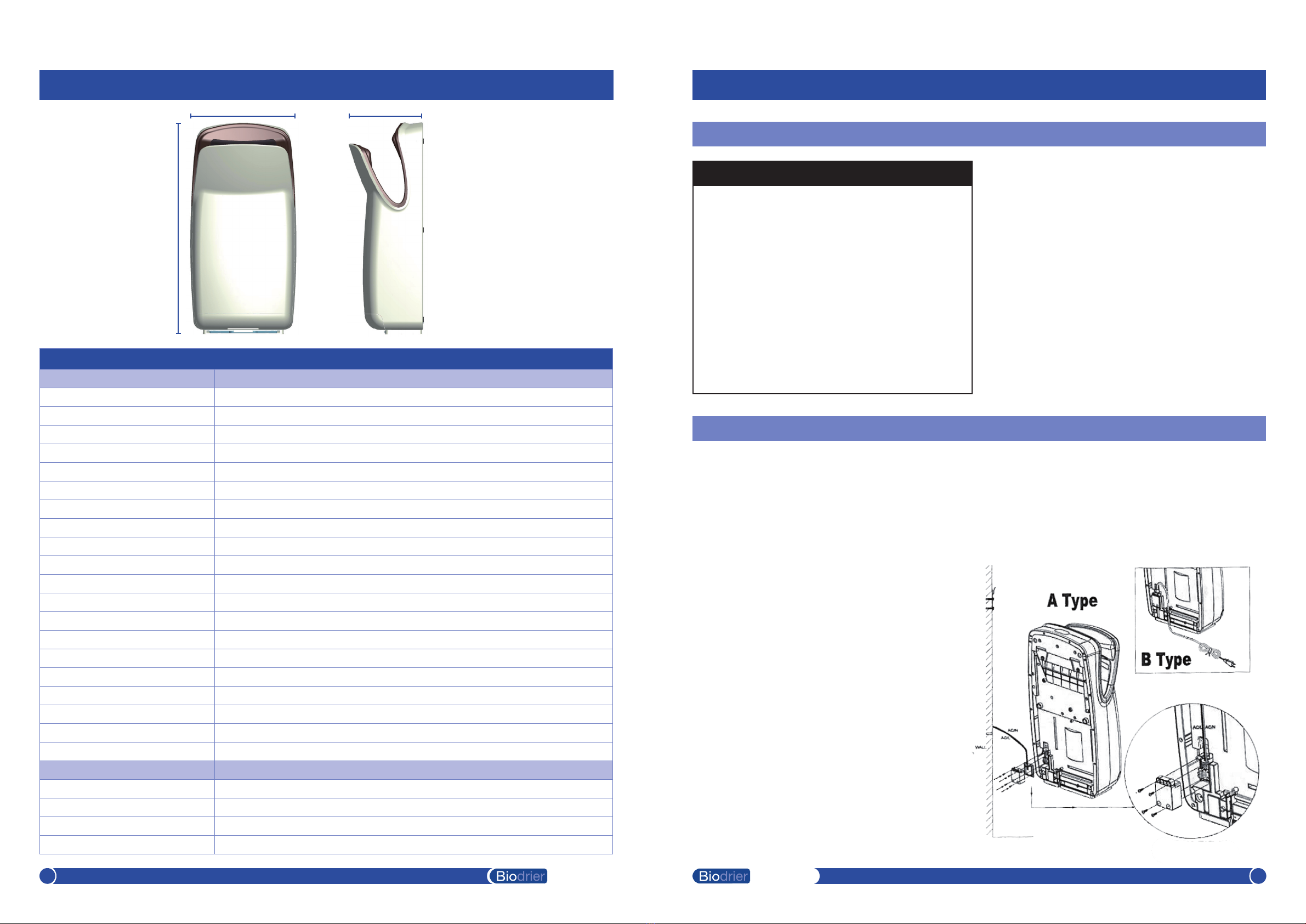
Technical Specications
Item Category Performance Data
Operating Voltage 220 - 240Vac, 50-60 Hz, 1200 WATTS
Warm Air Speed Output 150 m/s
Display LCD instructions and countdown
Motor Type 35,000 rpm, 2 speed adjustable
Motor Thermal Protection Auto Resetting Thermostat turns unit o, 240V at 239°F (115°C)
Noise Level 80db (A) 1 metre
Water Tank LED indicator when tank is full
Filter Sensor LED indicator when lter is full
Air Purication Enzyme HEPA Filter H13 - simple cartridge replacement system
Air Freshener Bioger: moisturiser, sanitizer, air freshener
Water Tank & Filter Security Sliding locking system, lock both with one touch
Drying Time Less than 10 seconds
Circuit Operation Infared Automatic, self adjusting
Timing Protection 20 seconds auto shut o
Drip Proof IP33
Isolation CLASS 11
Certicates CE, GGS, ETL, WEEE
Net Weight 9 kg
Shipping Weight 10 kg
Unit Size 330mm W x 660mm H x 230mm D
Item Code Cover Type/Finish
BE1000W Fire proof ABS, 94VO, PC, PMMA, UV Coated
BE1000S Fire proof ABS, 94VO, PC, PMMA, UV Coated
BE1000B Fire proof ABS, 94VO, PC, PMMA, UV Coated
BE1000G Fire proof ABS, 94VO, PC, PMMA, UV Coated
Operating Instructions and Parts Manual
Surface Mounted High Speed Hand Dryer
Executive
1Executive 2
General Safety Information
This product is intended for installation by a
qualied service person. Use AWAG No.16 solid
conductor for wiring.
Failure to properly ground unit could result in
electrical shock and/or death.
Disconnect power at the service breaker before
installing or servicing.
NOT FOR HOUSEHOLD USE - MAY CAUSE BURNS
“IMPROPRE A L’USAGE DOMESTIQUE - PUET
OCCASIONNER.”
• WARNING NOTE: Do not install dryer over wash basin.
Type Y attachment
If the power supply cord is damaged, it must be
replaced by the manufacturer or its service agent or a
similar qualied person in order to avoid a hazard.
Means for disconnection must be incorporated in the
xed wiring in accordance with the wiring rules.
Installation
1. Make sure power supply breaker is switched o.
Installation must be carried out in accordance with the
current edition of the local wiring regulations code
having jurisdiction. Installation should be performed
only by a qualied electrician.
2. Place template against wall at desired height
(see mounting height recommendations) and mark
locations of 4 mounting holes and wire service entry at
knockout (KO) location.
NOTE: For two or more dryers, dryers should be no
closer than 24 inches (610 mm) on centre.
4. Connect supply wires to terminal block where
indicated and connect ground wire to baseplate with
ground screw.
Connections:
A Type: Power cable not equipped
1. Secure the line and connect the power cable into the
proper terminal block locations. Verify connections are
correct before proceding.
2. Cover the power connector with the provided
housing cover (Power Supply Cover Kit)
Minimum wire cross section: 2x1mm
B Type: Power cabe equipped
330mm 230mm
660mm
Operating Instructions and Parts Manual
Surface Mounted High Speed Hand Dryer
Recommended Mounting Heights
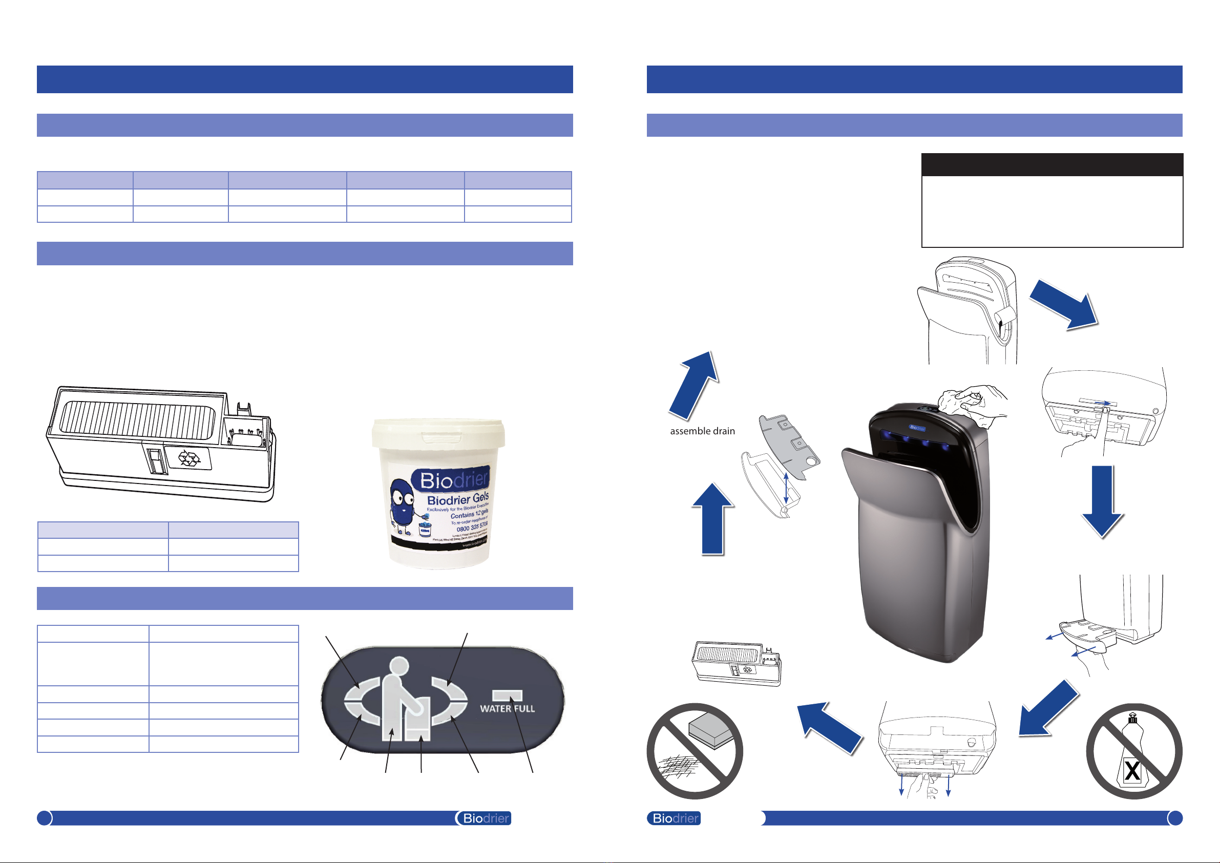
Consumables
Operation
Stand By Mode LED-5 Green light ON
Operating Mode LED-5 Blue Light ON &
LED-1 to 4 pulse in sequence
and then together twice
Water Tank Full LED-7 Blue Light ON
After Tank is Emptied LED-7 Light OFF
Change Filter LED-6 Light ON
After Filter Change LED-6 Light OFF
5. Clean lter casing by wiping with soft
damp cloth. Replace the antibacterial
lter every 3 months, or when LED 6
illuminates. Moisturising gels should be
replaced every month. Slide lter back
into place.
1. Pour a cup
of water down
drain hole. Use
cleaning brush
supplied to clean
drain hole.
3. Remove drain tank and empty.
6. Disassemble drain
tank and rinse clean
using a disinfectant,
then replace.
4. Remove lter.
7. Wipe down the external
surfaces of the Biodrier
Executive hand dryer with a
soft cloth. Switch power back
on and test operation.
Operating Instructions and Parts Manual
Surface Mounted High Speed Hand Dryer
Cleaning and Maintenance Instructions
Men’s Ladies Children, ages 11-17 Children, ages 3-10 Disabled
13” 11” 10” 6” 4”
350 mm 300 mm 250 mm 150 mm 100 mm
• WARNING
• Never spray water directly onto hand dryer
• Never use any abrasives or harsh chemicals
• Turn o electricity prior to cleaning the hand dryer
Product Order Code
Antibacterial HEPA lter HD-BUSI-HEPA-FILTER
Moisturising Gel BE1000GELS
Periodic cleaning of the unit is recommended to
ensure optimum performance.
• Switch to service mode located internally, above the
water tank.
• Wipe the cover with a soft cloth and a mild cleaning
solution. Do not Soak. Never use abrasives to clean
the cover.
From oor to bottom of dryer.
Biodrier Anti Bacterial HEPA Filter
The Anti Bacterial Filter is tted to ensure dust and
airborne bacterias are restricted from entering the
internal components and airow of the dryer. The lter
should be replaced every 3-6 months, depending on
usage.
Biodrier Gels
Biodrier Gels are manufactured exclusively for Biodrier
and preforms 3 jobs in one:
1. Moisturise the hands.
2. Sanitise the product internally, and the users hands.
3. Fragrances the surrounding washroom area whilst in use.
The Gels are manufactured from natural sources and are
chemical free.
LED-1
LED-2 LED-3
LED-4LED-5 LED-6 LED-7
Executive
3Executive 4
2. Unlock the drip tray.
Operating Instructions and Parts Manual
Surface Mounted High Speed Hand Dryer
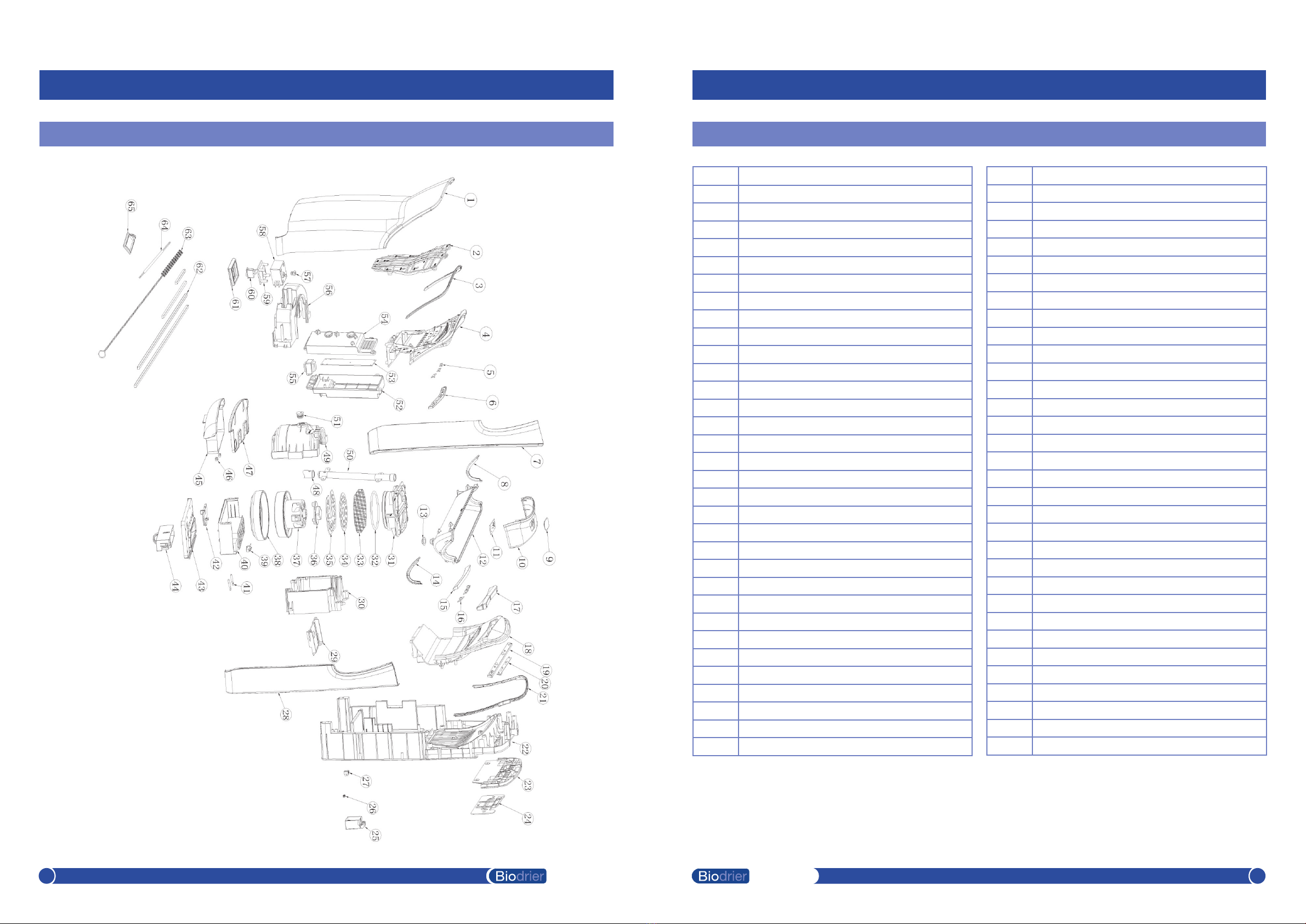
Diagram
Operating Instructions and Parts Manual
Surface Mounted High Speed Hand Dryer
Parts List
Key Description
1Cover front
2Duct front
3Silica gel
4Cover hand front
5PCB board
6Cover window front
7Cover side L
8SIlica gel
9Cover LED
10 Cover top
11 PCB board
12 Cover hand bottom
13 Silica gel
14 Silica gel
15 Cover window back
16 PCB board
17 Cover window LED
18 Cover hand back
19 Cover LED
20 PCB board
21 Silica gel
22 Cover main
23 Cover back
24 Bracket
25 Power supply cover
26 Cushion
27 Connection
28 Cover side R
29 Tube panel
30 Housing motor lower
31 Distributer air
32 Ring
33 Spange
34 Round Sheet
35 Sheet
36 Fixure
37 Motor
38 Airproof sheath
39 Switch
40 Grilol guide
41 Pole
42 Sheft panel
43 Filter support
44 Filter Ass’y
45 Bucket slop bottom
46 Connector panel
47 Bucket slop top
48 Tube
49 Housing motor upper
50 Water tube
51 Silica gel
52 PCB enclosure lower
53 PCB main
54 PCB enclosure lower
55 Transformer
56 Cover air tight
57 COB
58 Switch enclosure
59 Switch holder
60 Power switch
61 Silica gel
62 Silica gel (A B C D)
63 Cleaner
64 Internal wire to PCB
65 Silica gel pad
Executive
5Executive 6

FW3 LTD, Biodrier
West Hill, Exeter, EX11 1LQ
tel: +44(0)1404 814292 • email: sales@biodrier.com
This manual suits for next models
3
Other Biodrier Dryer manuals


