Biomark Submersible Battery User manual

www.biomark.com +1 208.275.0011 [email protected]
Overview
The Biomark Submersible Battery is shipped unassembled. This document covers the
assembly of the 72 Ah (2-week runtime) or 180 Ah (4-week runtime) submersible battery pack.
Please follow these procedures to successfully install and seal your submersible battery pack.
Failure to follow manufacturer guidelines and specifications may void Biomark’s manufacturer’s
warranty.
Shipment includes:
•(1) Submersible battery enclosure
•(1) Submersible battery enclosure entry plate with Battery Management System (BMS) &
Wiring
•(1) Sealing Gasket
•(2) Foam inserts
•(40) Stainless Steel ¼-20 x 2.5” partially threaded hex head screw – 7/16” hex size
•(80) Stainless Steel .281” ID .625” OD – standard ¼” flat washers used
•(80) Stainless Steel Nylon-Insert Locknut, 1/4"-20 Thread Size- 7/16” hex size
•Bus Bar Kit
oEach kit will include (2) Vertical and (1) Horizontal bus bars with the following
battery terminal hardware:
o72Ah Battery Terminal Hardware
(8) M6 - 1 x 12mm full thread hex head screw– 10mm hex size
QUICK START GUIDE
SUBMERSIBLE BATTERY
ASSEMBLY & INSTALLATION

SUBMERSIBLE BATTERY INSTALLATION
QUICK START GUIDE 2
(8) M6 6.4mm ID 11.4mm OD flat washer
(8) M6 6.5mm ID 11.8mm OD split lock washer
o180ah Battery Terminal Hardware
(8) M8 – 1.25 x 15mm full thread hex head screw – 13mm hex size
(8) M8 8.4mm ID 16mm OD flat washer
(8) M8 8.5mm ID 14.8mm OD split lock washer
•Tool Kit:
o(1) Fat Wrench Wheeler Torque Screwdriver Kit – ¼” drive
o(1) 7/16” combination wrench
o(1) 7/16” ¼” drive socket
o(1) 13mm socket (1/4” drive) (180 Ah Battery Cell)
o(1) 10mm socket (1/4” drive) (72 Ah Battery Cell)
Torque Specifications
LOCATION
TORQUE SPECIFICATIONS
Battery Terminal Hardware (72 Ah Pack)
30-inch pounds (in/lbs.)*
Battery Terminal Hardware (180 Ah Pack)
30-inch pounds (in/lbs.)
Entry Plate Hardware (40-sealing bolts)
30-inch pounds (in/lbs.)
*Use a minimum of 30-inch pounds of torque until you hear an audible click, or until the split
washer is fully compressed and the bolt is firmly secure.
Assembly & Installation Instructions
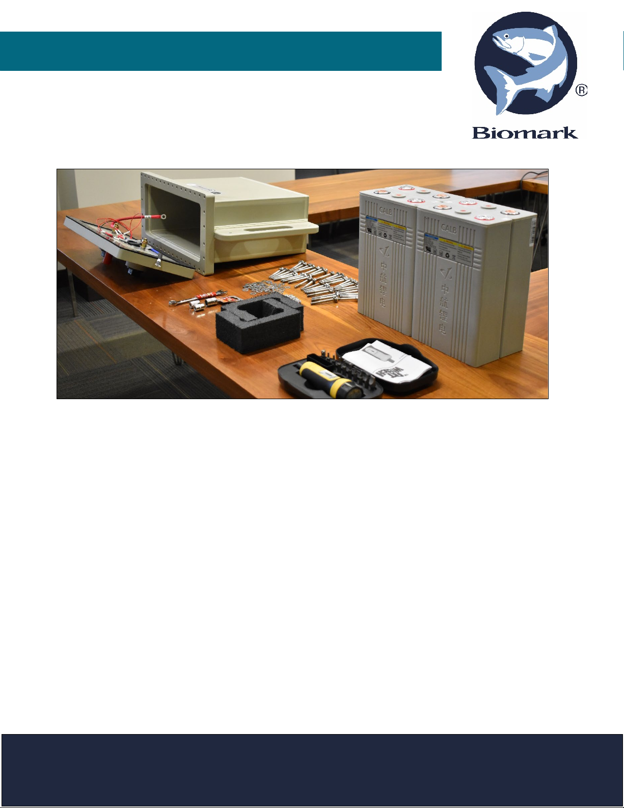
Assembly and installation of the submersible battery pack must be performed in a clean
environment to ensure proper seal of waterproof enclosure, and on a large flat surface, free of
contaminants or obstructions.
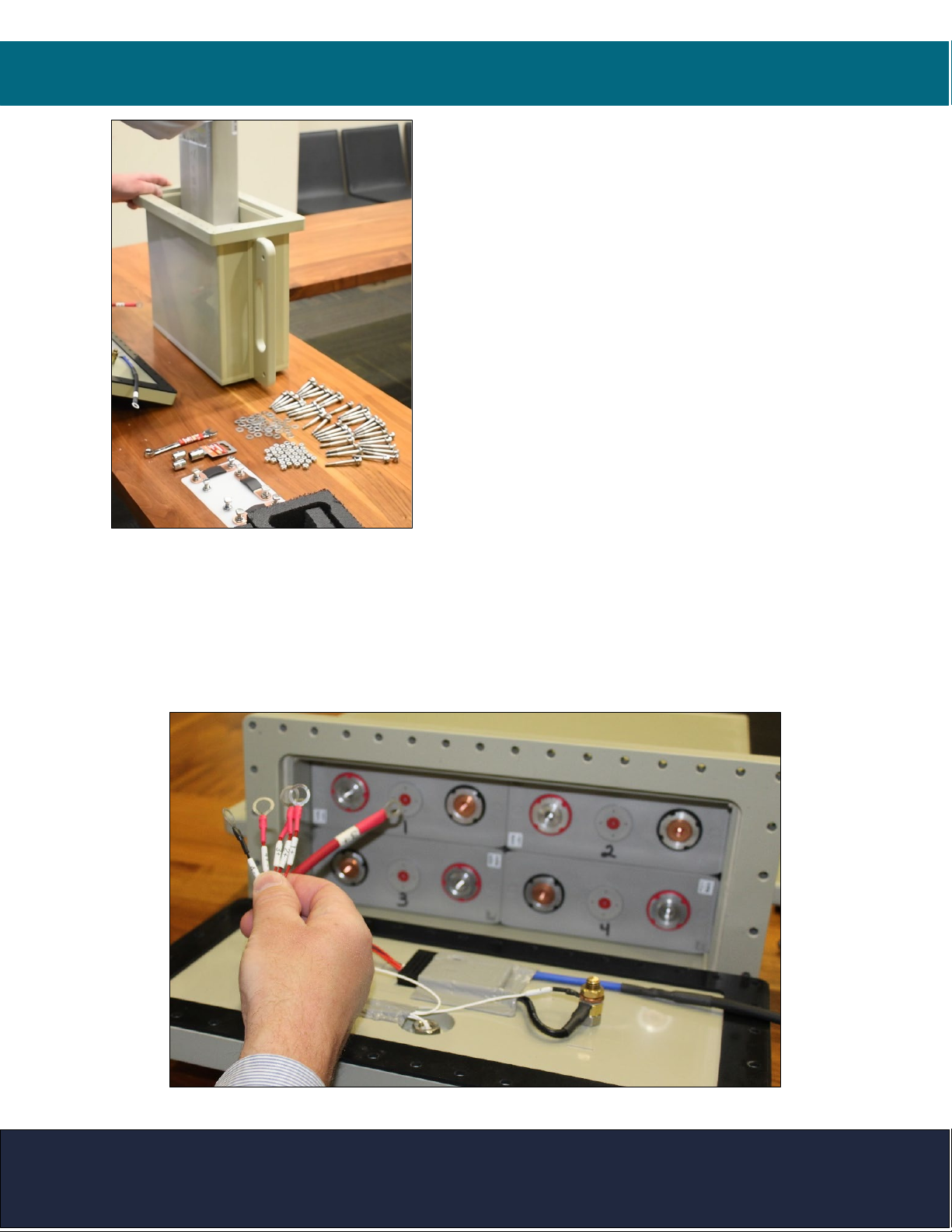
Step 1:Label Batteries
Label the batteries from 1-4 with a permanent marker to ensure proper installation of each
independent cell within the enclosure. Place the four battery pack cells in a 2 by 2
configuration, with cell 1 and 2 on top (orientated from left to right; positive (red) -negative
(black) and positive (red) - negative (black)) and 3 and 4 on the bottom (orientated from left to
right; negative (black) - positive (red), and negative (black) -positive (red)). Obtain proper
battery sequence prior to moving to step 2.

SUBMERSIBLE BATTERY INSTALLATION
QUICK START GUIDE 3
Step 2: Install Battery Cells into the
Submersible Battery Box
For easy installation of battery cells into battery box,
tilt battery box vertically so opening is orientated
upward and label on outside of box is facing away
from you. Install battery cell #4 into bottom right
position of battery box (orientation is negative-
positive). Install battery cell #3 into bottom left
position of battery box (orientation is negative-
positive). Install Battery cell #2 into top right position
of battery box (orientation is positive-negative). Install
Battery cell #1 into top left position of battery box
(orientation is positive-negative).
TIP: Battery box is constructed for tight fit of each cell
within box, allowing batteries to drop into place is
acceptable. If you have trouble achieving proper
battery placement, please contact us.
Step 3:Battery Management System
Observe the battery management system (BMS) located at the center of the battery pack entry
plate. This device maximizes the charging sequence for each 3.2 V cell within the submersible
battery pack. Each positive terminal of all (4) battery cells will connect to the BMS via labeled
(Red) wire. In addition, the negative (blue/black) wire will connect the BMS to the negative
terminal of battery #4.

SUBMERSIBLE BATTERY INSTALLATION
QUICK START GUIDE 4
Step 4: Install Bus Bars & BMS Wiring for 12 Volt Battery
Configuration
Lay the battery box (Horizontally) onto a
flat surface with the battery label faced up.
Remove vertical (Left) bus bar and
associated battery terminal hardware from
included packaging. Slide ring terminal of
Red wire (labeled #1 extending from BMS)
over end of provided battery terminal bolt,
and through top hole of vertical bus bar.
NOTE: Proper placement of hardware is in
the following order - Bolt- head-split lock
washer-flat washer-ring terminal-bus bar.
Install bolt/ring terminal/bus bar assembly into positive terminal of battery cell #1, and hand
tighten. Install remaining terminal bolt into bottom hole of vertical bus bar and into negative
terminal of battery #3.
Next, remove from packaging and install horizontal bus bar from negative terminal of battery #1
to positive terminal of battery #2 (repeat above process to ensure (Red) #2 wire from BMS is
installed to positive terminal of battery #2).
Install remaining vertical bus bar from negative terminal of battery #2 to positive terminal of
battery #4 (repeat above process to ensure (Red) #4 wire from BMS is installed to positive
terminal of battery #4).
TERMINAL
RIGHT BUS BAR
LEFT BUS BAR
TOP BUS BAR
TERMINAL RED WIRE 1
TERMINAL RED WIRE 4

SUBMERSIBLE BATTERY INSTALLATION
QUICK START GUIDE 5
Step 5. Connect Entry Plate to Battery Cells
Place the battery entry plate in front of the battery box assembly with the positive (Red) wire
facing left, and negative (Black) facing right.
Install positive (Red) wire extending from the battery pack entry plate to positive terminal of
battery #3. Ensure positive (Red) wire extending from battery pack entry plate, and (Red)
wire labeled #3 from BMS, are placed onto terminal bolt and secured to positive terminal
of battery #3.
Repeat similar steps to install negative (Black) wire extending from battery pack entry plate, and
(Black) #4 black wire extending from BMS, to negative terminal of battery #4.
Step 6. Properly Tighten Battery
Terminal Hardware
Unpackage provided torque screwdriver and
set to 30-inch pounds.
*NOTE: Failure to torque battery hardware to
manufacturer’s specifications may cause
adverse battery performance.
Twist the base
of the Fat
Wrench until
the black line in
the white
indicator
reaches
30 in. – Lb.
Table of contents
Popular Camera Accessories manuals by other brands

Trojan
Trojan GC2 48V quick start guide

Calumet
Calumet 7100 Series CK7114 operating instructions

Ropox
Ropox 4Single Series User manual and installation instructions

Cambo
Cambo Wide DS Digital Series Main operating instructions

Samsung
Samsung SHG-120 Specification sheet

Ryobi
Ryobi BPL-1820 Owner's operating manual