1
Table of Contents
Description, Indications for Use, and Contraindications .............................................................................. 2
Description ............................................................................................................................................................................................................................................................ 2
Indications for Use .............................................................................................................................................................................................................................................. 2
Contraindications................................................................................................................................................................................................................................................ 2
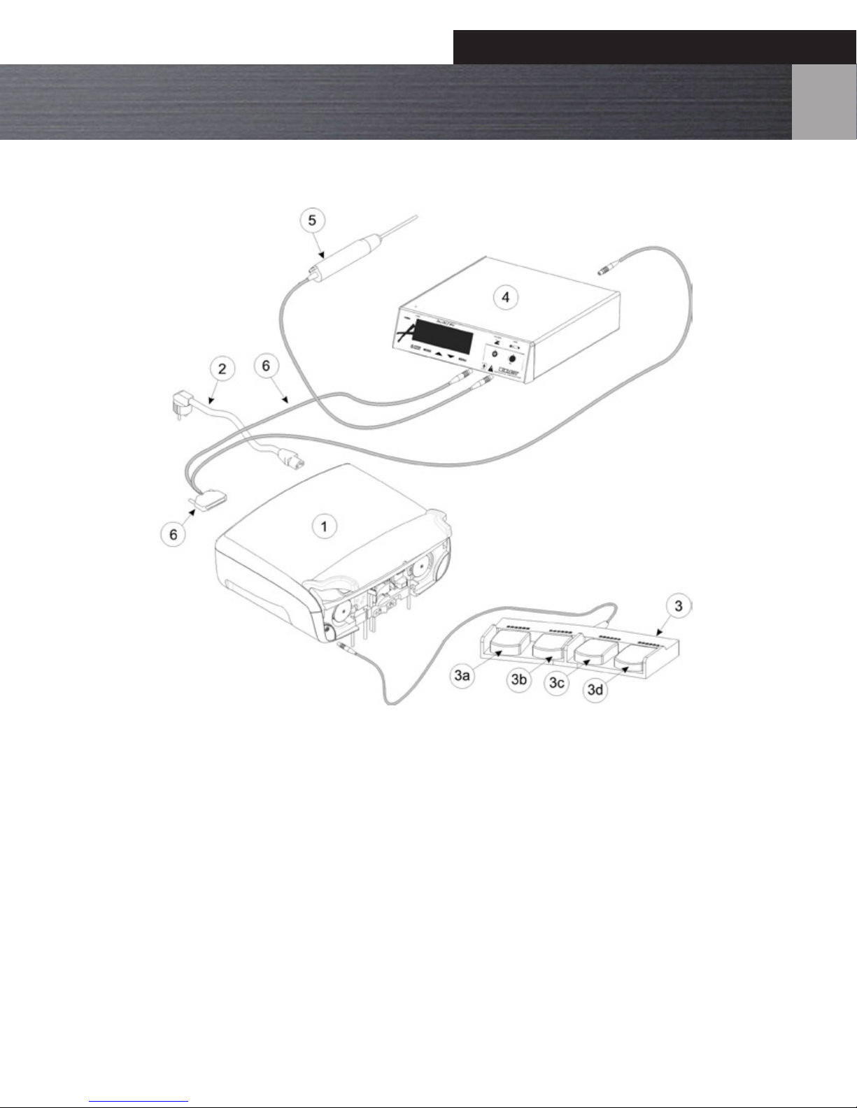
System Overview .............................................................................................................................................. 3 – 5
Connection Diagram with PowerTek™II Plus ............................................................................................................................................................................................. 3
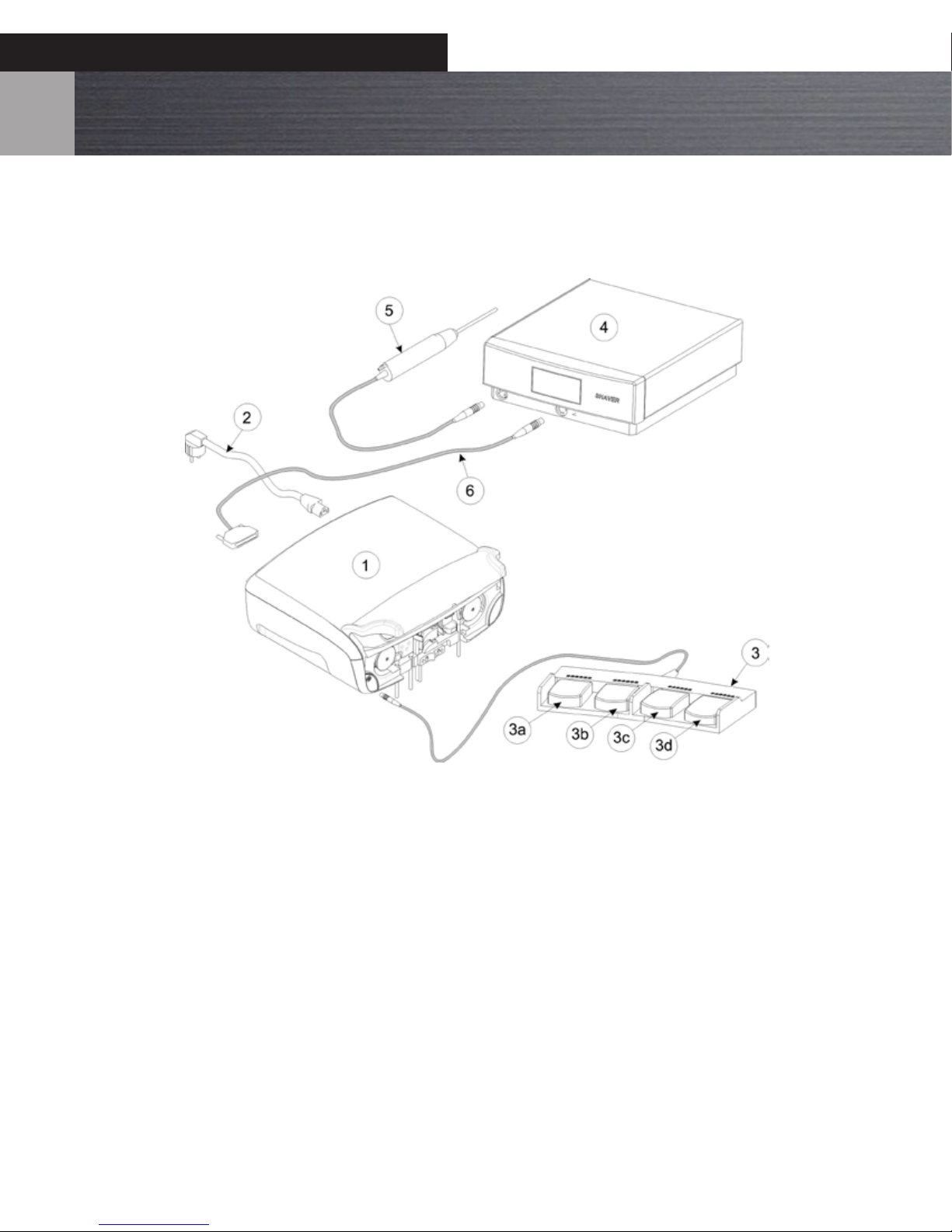
Connection Diagram with shaver other than PowerTek™II Plus......................................................................................................................................................... 4
Shaver control by use of the pump’s foot control.................................................................................................................................................................................... 4
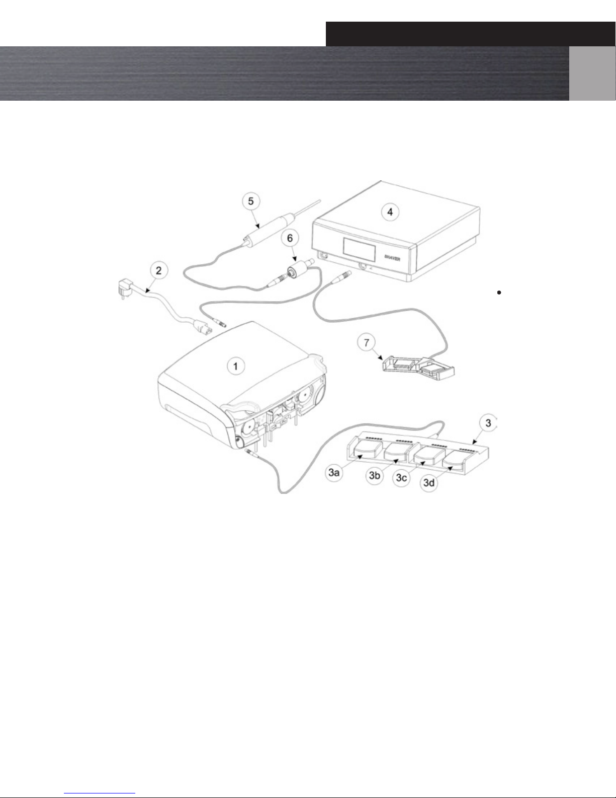
Connection Diagram with shaver other than PowerTek™II Plus......................................................................................................................................................... 5
Shaver control by use of the pump’s foot control or hand control. .................................................................................................................................................. 5
Principle of Operation...................................................................................................................................... 6
Warnings, Precautions, and Adverse Events .................................................................................................. 7 – 8
Warnings................................................................................................................................................................................................................................................................. 7
Precautions............................................................................................................................................................................................................................................................ 7
Adverse Events ..................................................................................................................................................................................................................................................... 8
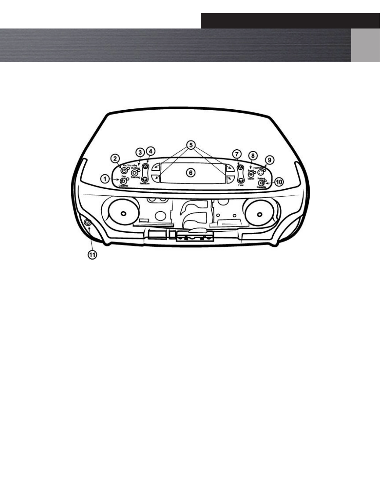
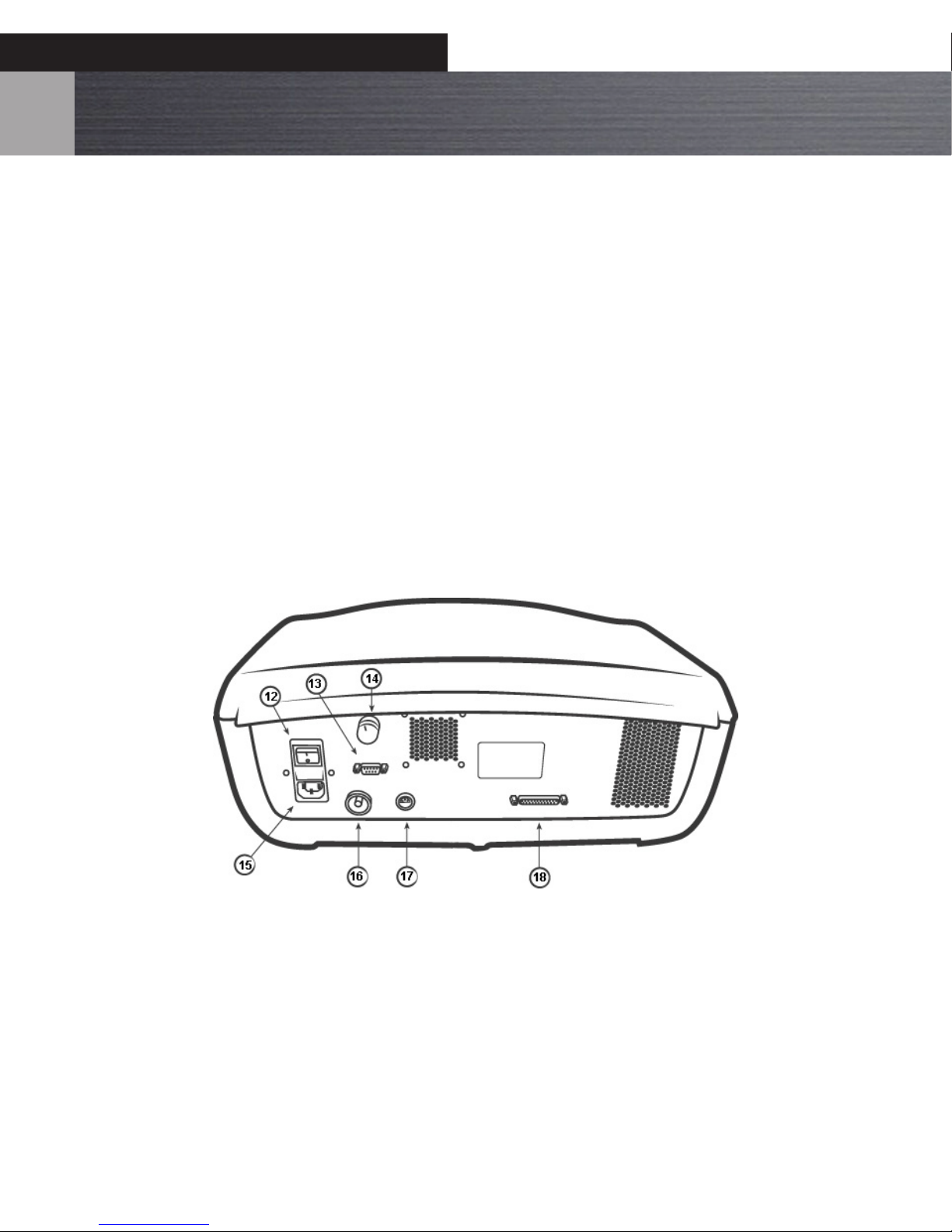
Controls, LEDs, and Alarms.............................................................................................................................. 9 – 12
Controls & LEDs.................................................................................................................................................................................................................................................... 9
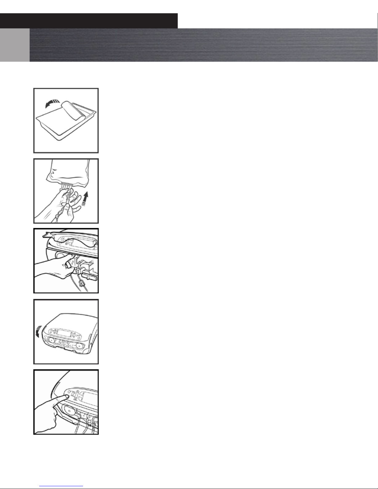
Unpacking.............................................................................................................................................................................................................................................................. 12
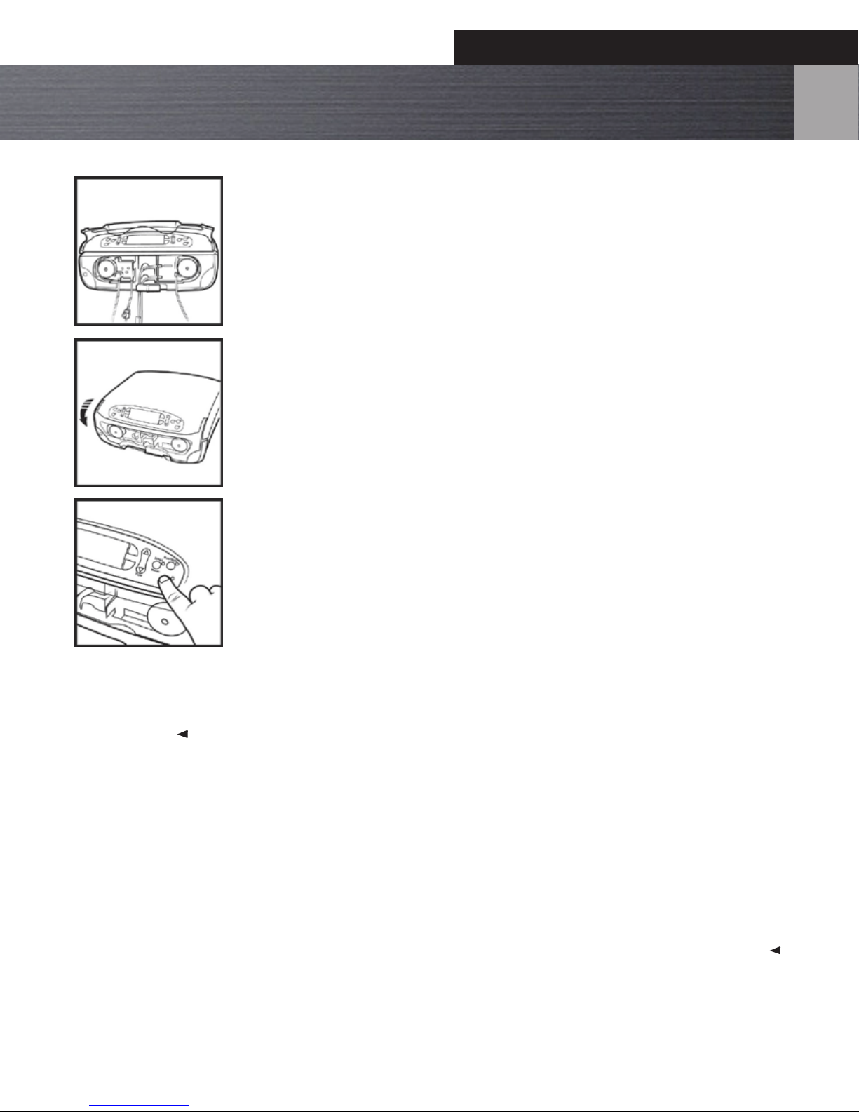
Assembly and System Check........................................................................................................................................................................................................................... 12
Instructions for Use .......................................................................................................................................... 13 – 20
Operator Training Requirements ................................................................................................................................................................................................................... 13
Starting the Procedure ..................................................................................................................................................................................................................................... 13
Load the cassettes............................................................................................................................................................................................................................................... 13
Joint Selection ...................................................................................................................................................................................................................................................... 13
Cassette Loading and Unloading .................................................................................................................................................................................................................. 13
Loading a Day Cassette..................................................................................................................................................................................................................................... 14
Connecting the Irrigation Tubing.................................................................................................................................................................................................................. 15
Loading a Patient Cassette............................................................................................................................................................................................................................... 16
PowerPump™ DP Function and Adjustment During Procedure ........................................................................................................................................................ 18
Changing Default Settings............................................................................................................................................................................................................................... 19
Cassette Removal ................................................................................................................................................................................................................................................ 20
System Shut Down.............................................................................................................................................................................................................................................. 20
Shaver Interface Box Instructions ................................................................................................................... 21
PowerPump™ DP Control of Shaver.............................................................................................................................................................................................................. 21
Shaver Control of the PowerPump™ DP...................................................................................................................................................................................................... 21
Cleaning Instructions......................................................................................................................................................................................................................................... 21
Troubleshooting Guide Shaver Interface Box ........................................................................................................................................................................................ 21
Alarms................................................................................................................................................................ 22
System Care....................................................................................................................................................... 23
System Environmental Requirements ......................................................................................................................................................................................................... 23
Equipment Disposal ........................................................................................................................................................................................................................................... 23
Surface Cleaning & Disinfection of Pump and Foot Control................................................................................................................................................................ 23
Maintenance and Troubleshooting................................................................................................................. 24
Maintenance ......................................................................................................................................................................................................................................................... 24
Troubleshooting Guide ..................................................................................................................................................................................................................................... 24
System Does Not Power Up After the Power Switch is Set to On. ..................................................................................................................................................... 24
Fuse Replacement............................................................................................................................................................................................................................................... 24
Front Cover Replacement................................................................................................................................................................................................................................. 24
Error Codes ............................................................................................................................................................................................................................................................ 24
Technical Specications................................................................................................................................... 25
Symbols Key...................................................................................................................................................... 26
Pump Classication and Safety Verication................................................................................................... 27
Classication ......................................................................................................................................................................................................................................................... 27
Safety Verication ............................................................................................................................................................................................................................................... 27
Ordering Information....................................................................................................................................... 28
Customer Service.............................................................................................................................................. 29
Warranty Information ........................................................................................................................................................................................................................................ 29
Product Complaints............................................................................................................................................................................................................................................ 29
Distributed by:...................................................................................................................................................................................................................................................... 29