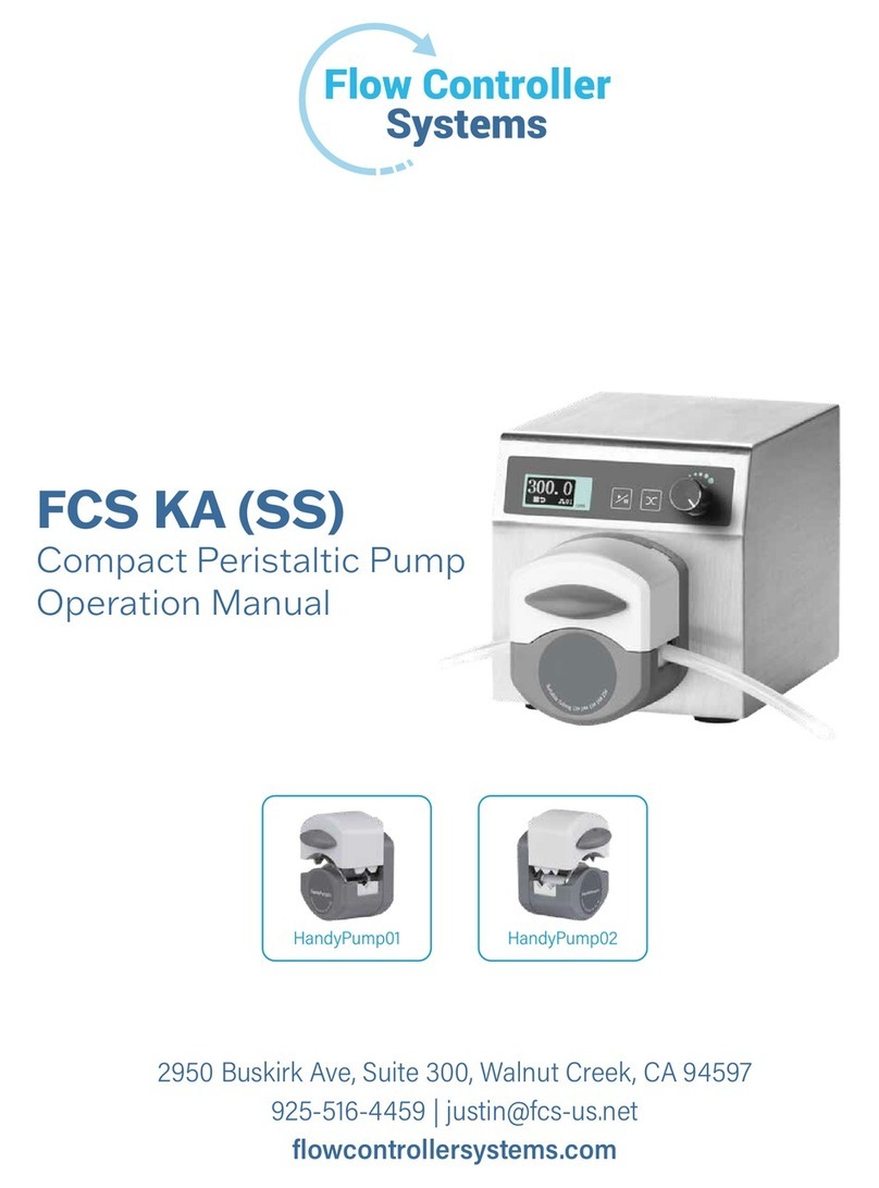
Flow Controller Systems FCS KA1 User manual

FCS KA1
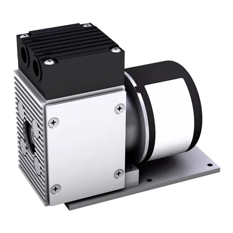
Compact Peristaltic Pump
Operation Manual
!"#$%&'()*+)%,-./%0'*1.%2$$/%3456'1%7+..)/%7,%"8#"9%%%%%%%%%%%%
"!#:#;<:88#"%=%>'(1*6?@A(:'(B6.1%%%%%%%%%%%
!"#$%#&'(#"")(*+*'),*-%#,

Note:
Ø Please read the manual carefully before operating the product.
Warning:
Ø Tubing may have crack due to wear. It results in the overflow of fluid from tubing. In that time human body and instruments
may be harmed. So users must check frequently and change tubing in time.
Ø Connect the power cord to the wall socket directly, and avoid using the extended electric wire.
Ø If the power cord or plug had wear and other damage, please disconnect the plug. (Hold the plug instead of the wire)
Ø If following situations happened, please turn off the power supply and disconnect the plug. (Hold the plug instead of the wire)
1. Fluid splash on the pump.
2. You think the pump need to maintain or repair.
Ø The user’s power socket must have ground wire, and have reliable grounding.
Note: The foot pedal switch and other external control plugs must be connected or disconnected in the power-off status to prevent the
external control interface from being burned.

Catalogue
1. Product Introduction ............................................................................................................................................................................ - 1 -
2. Product Appearance and Interface Instruction .................................................................................................................................... - 1 -
3. Operation Panel Instruction ................................................................................................................................................................. - 1 -
4. Operation Interface Structure .............................................................................................................................................................. - 2 -
5. External Control Interface ................................................................................................................................................................... - 7 -
6. Technical Parameters ........................................................................................................................................................................... - 8 -
7. Main Function and Feature ................................................................................................................................................................. - 9 -
8. Dimension Drawing ............................................................................................................................................................................ - 9 -
9. Maintenance ........................................................................................................................................................................................ - 9 -
10. Warranty and After-sales Service ...................................................................................................................................................... - 9 -

KA1
- 1 -
1. Product Introduction
KA1 adopts ABS engineering plastic housing, 2.4 inch LCD screen, low power, ultra-quiet, compact structure. Easy to operate with
digital knob speed control. A variety of external control methods for option. Support RS485 communication, standard MODBUS
communication protocol (RTU mode); It is suitable for complex working environment with super anti-interference and wide voltage
design.
Suitable pump head: KT15 pump head.
2. Product Appearance and Interface Instruction
A——Drive
B——Pump Head
C——Fan
D——External Control Interface
E——USB Port
F——Power Supply Interface
3. Operation Panel Instruction
KA1 can meet variety of working environment with pure imported keyboard, which has 300000 times lives.
l Start/Stop Button: Press [Start/stop] button, pumps run according to current speed, press [Start/stop] button again, pumps stop
running.
l Reversing Button: Press [reversing] button once, pump will change running direction once.
l Full Speed Button: When in stopping state or transferring state, press [Full speed], the pump will run with highest speed. This
button can be used for washing tubing or fast filling liquid.
l Knob: Rotate [knob] in main interface to adjust speed and flow will change.
In stopping status, press [knob] enter to [Menu selection interface], rotate [knob] to select corresponding items. Press [knob]
to select parameter which needed to change when setting parameters.
Knob
Start/stop
Full speed
Reversing

KA1
- 2 -
4. Operation Interface Structure
4.1 Booting Interface
When power on, enter to the booting interface, the system will enter to the English main interface after waiting for 2.5s.
4.2 Main Interface
Main interface structure as the follow picture:
Running status: Animation shows current running status and running direction.
Back suction angle: If already set the back suction angle, then it will display the logo of back suction angle; If the back suction angle is
0, then it will not display.
Start/stop: The pump displays or when in start status; The pump displays when in stop status.
Direction: The screen displays when in clockwise, displays in counterclockwise.
Flow/speed displays: Displays the flow value with the current pump head, tubing and speed.
Parameters: Displays all the basic parameters for the current pump.
4.3 Setting Menu Selection Interface
Operating steps:
a. When in stop status, press [Knob] enter to menu selection interface in main interface.
b. Rotate [Knob] with the green box moving right or left to select needed setting parameters.
c. Press [Knob], enter to next interface and set parameters.
d. Select [ESC] menu, press [Knob], back to main running interface.
e. Failure to press other buttons.
Running
status
Back suction
angle
Start/stop
Direction
Flow
Speed
Set
parameter
Head
Tube
COMM
Ex.Speed Off
Setting Cal Com
Ext. Ext.Speed Esc

KA1
- 3 -
4.3.1 Basic Configuration Interface
Operating steps:
a. Press [Knob] to select tubing in setting interface, when in status (1) , rotate [Knob], the cursor up and down, select the tubing or
back suction angle.
b. When in status (1), press [Knob] button, change to status (2).
c. When in status (2), rotate [Knob] button, select tubing.
d. When in status (2), press [Knob] back to status (1), ensure the inputting value.
e. When in status (1), cursor moves to Back, press [Knob] to back to menu selection interface.
Set back suction angel, the angle range is 0-360° (360° is a full circle of back suction). When the angle is 0, it means turning off back
suction function.
Note: When turn off back suction angle, the main interface does not display the mark of back suction angle. Only when turn on it, the
main interface will display the mark.
4.3.2 Flow Calibration Interface
Operation steps:
a. After enter the interface, the default test time is 60 seconds, the actual liquid volume defaults to the liquid volume displayed
according to the current set flow.
b. Press [Knob] button to select test time, when in status (1), rotate [Knob] and the cursor moves to actual volume line, then press
[Start/stop] button, the motor start running, and start calibration. The countdown is displayed at the test time.
c. When in status (1), press [Knob] button, switch to status (2), when in this status, rotate [Knob] button, set the test time.
d. After the countdown, the cursor move to actual volume directly, input the actual volume with rotating knob.
e. Also can directly choose actual volume box, press [Knob] button to set the actual liquid volume.
f. After input, press [Knob], ensure inputting, a dialog box with “Calibration complete” will pop up in this interface, that means
completing calibration. Press [Knob] button back to calibration interface.
g. Reset the calibration function: Choose [Yes], press [Knob] button, a dialog box with “Reset calibration completes” will pop up in
this interface, that means the calibration data can be reset.
h. After calibrating, then back to main interface, the speed will not change, the flow will change according to calibrating actual
volume. If the speed is 100rpm, the previous corresponding flow is 20mL/min, the actual liquid volume tested in 60 seconds is
30ml/min, after calibrating, the speed displayed in main interface is 100 rpm, the flow is 30L/min.
FD15
19#
1
360
Head&Tube
Head:
Tube: 13#
Suck back: 0
esc
KT15
FD15
19#
2
360
Head&Tube
Head:
Tube:
Suck back: 360
esc
KT15
19#
60.0
215.38 mL
1
60.0
215.38 mL
2
Calibration Calibration
Time: Sec
Volume:
Reset: No
esc
Time:
Volume:
Reset:
esc
No
Sec

KA1
- 4 -
4.3.3 Setting Communication Interface
Operation steps:
Serial communication is always on, and the on / off option is not set.
a. In setting communication interface, press [Knob] button to select native address, when in status (1), rotate [Knob] button to select
native address or baud rate.
b. In status (1), press [Knob] button, move to status (2).
c. In status (1), rotate knob to ESC position and press the [Knob], then back to [Menu selection interface].
d. In status (2), rotate [Knob] button to select native address (01-32) or baud rate: 9600.8.e.1/9600.8.n.1/19200.8.e.1/19200.8.n.1.
e. In status (2), press [Knob] button, back to status (1) and ensure items.
The product support Modbus communication protocol--RTU mode, communication interface RS485;
Baud rate means:
Symbol
Baud
rate
Data
bits
Stop bit
Check
bit
9600.8.e.1
9600
8
1
Parity
check
9600.8.n.1
9600
8
1
No
check
19200.8.e.1
19200
8
1
Parity
check
19200.8.n.1
19200
8
1
No
check
4.3.4 External Control Start/stop, Reversing Interface
Operation steps:
a. At external control start/stop, reversing interface, press [Knob] button to select external control start/stop, when in status (1), rotate
[Knob] button, select external control start/stop, reversing or signal.
1
RS485
9600.8.e.1
1
1
RS485
9600.8.e.1
2
Communication Communication
Port: Port:
Address: Address:
Baud rate: Baud rate:
esc esc
1
2
Ex.control Ex.control
On/off: On/off: On
CW/CCW:
Signal: Pulse
Off
Off
esc esc
Signal: Pulse
CW/CCW: On

KA1
- 5 -
b. When in status (1), press [Knob] button to status (2).
c. When in status (1), rotate knob to ESC position and press the [Knob], then back to [Menu selection interface].
d. When in status (2), rotate [Knob] button to select turning on/off external control start/stop, turning on/off external control reversing
or selecting signal to level/pulse (The corresponding inner control button does not make effect in level mode).
e. When in status (2), press [Button] back to status (1) and ensure the items.
Note:
External control start/stop, reversing signal is default passive signal; If you want to change it to positive signal, please contact with the
manufacture.
There are two modes for external control start/stop, reversing: level and pulse. Please see the external control interface part for the details.
The switches are set independently for various external control modes, which only works after the corresponding external control
function is turned on.
4.3.5 External Control Speed Interface
Operation steps:
a. At the external speed control interface, press [Knob] to select external control speed regulation, when in status (1), rotate [Knob]
button, the cursor moves up and down to select external control speed, signal, maximum speed.
b. When in status (1), press [Knob] button to status (2).
c. When in status (2), rotate [Knob] button to select turning on/off external control speed or selecting signal: 0-5V/0-10V/4-20mA,
or select maximum speed.
d. When in status (2), press [Knob] button, back to status (1), and ensure items.
e. When in status (1), rotate [Knob] button in clockwise enter to customized interface of external control speed regulation, as follow
picture shows:
f. When in status (1), rotate [Knob] button to select (0V corresponding speed: 0) or (5V corresponding speed: 350). You can set the
corresponding speed freely within the speed range specified by the purchased model. The peristaltic pump will automatically create
a liner speed relationship between analog values.
g. When in status (1), press [Knob] button to status (2).
h. When in status (1), roll to esc position, press [Knob] back to [Menu selection interface].
i. When in status (2), rotate [Knob] button to set various parts corresponding speed.
j. When in status (2), press [Knob] button, back to status (1), ensure items.
0-5V
350.0
1
0-5V
350.0
2
Ex.speed Ex.speed
On/Off: Off On/Off: On
Signal:
MaxSpeed:
Signal:
MaxSpeed:
5V
0V 0.0
350.0
1
5V
0V0.0
350.0
2
Ex.speed Ex.speed
0Vspeed: 0Vspeed:
5Vspeed: 5Vspeed:
esc esc

KA1
- 6 -
Note:
Select analog speed regulation signal according to external port inputting signal, there are three options: 0-5V, 0-10V,4-20mA.
External control speed regulation can set the maximum speed for the pump, the maximum speed is 350rpm, the analog signal voltage
range is liner with the motor speed.
If the maximum speed is not 350rpm, the motor speed will be limited by the analog signal, motor speed analog signal
When the motor speed and analog signal reach the set maximum speed according to the corresponding proportional relationship, the
analog signal will be increased at this time, and the motor speed will run at the set maximum speed and will not increase with the analog
signal.(For example: Set the corresponding speed of 0V to 0 rpm, the corresponding speed of 5V to 350 rpm (2.5V should be 175rpm),
set the maximum speed to 175 rpm, external control inputting analog signal is 2.5V, the motor speed is 175 rpm in the time. The motor
speed will remain uncharged at 175 rpm after the input signal exceeds 2.5V.

KA1
- 7 -
5. External Control Interface
The external control interface of 15 hole base is shown in the figure below:
l The external control interface is 15 hole base, the function of 15 hole pin is:
Pin1 is the external control start/stop port;
Pin2 is the external control reversing port;
Pin3 is empty.
Pin4 is RS485 B-;
Pin5 is RS485A+;
Pin6 is 0-5V signal terminal of analog speed regulation;
Pin7 is 0-10V signal terminal of analog speed regulation;
Pin8 is 4-20mA signal terminal of analog speed regulation;
Pin9 is AGND common port of analog speed regulation;
Pin10 is empty;
Pin11 is negative terminal (POWER_GND) of status output;
Pin12 is status output terminal;
Pin13 is positive terminal (POWER_VDD) of status output;
Pin14 is the positive terminal of internal isolated 5V output;
Pin15 is the negative terminal of internal isolated 5V output.
(1) External control start/stop, reversing:
Set external control mode in external control setting interface, turn on corresponding external control function, the external control signal
input port is valid.
Ø Pin1 is the external control start/stop port:
In pulse mode, pin1 is short-circuited with pin14 and then disconnect, the motor will run, do it one more time, the motor will stop; In
level mode, pin1 is short-circuited with pin14, the motor will run, disconnect them, the motor will stop.
Ø Pin2 is the external control reversing port:
In pulse mode, pin2 is short-circuited with pin14 and then disconnect them once, the motor direction will change once; In level mode,
pin2 is short-circuited with pin14, the motor will run with clockwise, disconnect them, the motor will run with counterclockwise.
Ø Pin14 is the common port of external control start/stop, reversing
Note:
1) When the external control is turned on level mode, the membrane keypad will not make effect.
2) The pump defaults to passive external control signal, the above description is also the default state. If you need active
external control signal, please contact with manufacture.
(2) RS485 communication port: Select pump address and communication baud rate in communication setting interface.
Ø Pin5 RS485A: Connect RS485 A+ port
Ø Pin4 RS485B: Connect RS485 B- port
Note: The communication protocol is standard MODBUS protocol.
(3) Analog signal input port: After selecting external control speed regulation signal in external control setting interface, turn on the
1
15
5
610
11

KA1
- 8 -
function of external control speed regulation. Control motor speed from 0rpm to maximum speed by analog signal.
Ø Pin6 0-5V: 0V-5V voltage signal input terminal
Ø Pin7 0-10V: 0V-10V voltage signal input terminal
Ø Pin8 4-20mA: 4-20mA current signal input terminal
Ø Pin9 AGND: The negative port of analog signal.
Note: It is forbidden to connect 0-10V signal with 0-5V or 4-20mA input terminal. Wrong connection will damage the equipment.
(4) The output terminal of motor running status: Output the motor running status:
1) Connect Power-VDD with external power supply 5V positive;
2) Connect Power-GND with external power supply 5V negative;
3) Start motor, the relay pull in; the motor stop, the relay disconnect.
l The square Port USB interface is shown in the figure below
Square Port USB interface, equipped with square port data cable, can be used to update and upgrade internal programs.
6. Technical Parameters
Speed range
0.1-350rpm
Power supply
adapter
Output: (24V/1.25A)
Input: AC100V-240V,
50Hz/60Hz
Speed
resolution
0. 1rpm
Communication
interface
RS485 support Modbus
communication protocol
(RTU mode)
Operation
Mechanical key +
digital knob
Dimension
(L*W*H)
188*128*135mm
Display
method
2.4 inch LCD screen
Weight
1.1kg
External
control signal
0-5V, 0-10V, 4-20mA
Start/stop,
reversing signal
Switch signal (The default
is passive signal. Optional
active signal)
Output
interface
Open collector
output
Relative
humidity
<80%
Temperature
0-40℃
Power
consumption
<30W
IP rage
IP31

KA1
- 9 -
7. Main Function and Feature
Ø 2.4 inch true color LCD display.
Ø Ultra-quiet drive settings, accurate control, low vibration and noise.
Ø Mechanical keypad and menu interface are convenient for users setting parameters.
Ø Easy to operate speed regulation by digital knob.
Ø Var i ou s e x te r na l c o nt r ol fu nc t io n s, th e re ar e 3 an al o g s ig n al sp eed regulations: 0-5V, 0-10V, 4-20mA.
Ø Power down memory function, save the data in time.
Ø It is suitable for complex working environment with super anti-interference and wide voltage design
Ø Fast filling function, which can not only clean the tubing, but also fill the tubing with liquid.
8. Dimension Drawing
Unit: (mm)
9. Maintenance
Ø Check the running status of machine before starting it, normal operation can be put into use.
Ø Check for leakage, and correct fault which can be appeared.
Ø Clean liquid overflowed from the pump in time.
Ø Please turn off the power supply and unplug the power socket (Hold the socket instead of power cord) when liquid splashed on
pump. Check whether liquid flows into the machine, if it does, please contact the manufacture.
Ø The foot pedal switch and other external control plugs must be connected or disconnected in the power-off status to prevent the
external control interface from being burned.
Ø The user’s power socket must have ground wire, and have reliable grounding.
Ø This product has no waterproof measures. Please take protective measures when using in water environment.
Ø This product does not have special certification such as medical certification. When it needs to be used in special fields such as
medical and military, please self-certify.
Ø If the pump does not use for a long time, please clean it and keep it in dry and ventilated environment.
Ø The company shall not bear the direct and indirect losses caused by the malfunction or improper operation of this product.
10. Warranty and After-sales Service
We support 3 years warranty for the pumps, subject to the exceptions below. Our company shall not be liable for any loss, damage, or
expense directly or indirectly related to or arising out of the use of its products. This warranty does not obligate our company to bear
any costs of removal, installation, transportation, or other charges which may arise in connection with a warranty claim.
If the pump fails during the warranty period, after confirmation by our technical department, we will provide spare parts free of charge.
Customers will need to bear the shipping cost.
Exceptions:

KA1
- 10 -
Ø The warranty shall not apply to repairs or service necessitated by normal wear and tear or for lack of reasonable and proper
maintenance.
Ø All tubing and pumping accessories as consumable items are excluded.
Ø Electrical surge as a cause of failure is excluded.
Ø Chemical attack is excluded.
Ø Improper operation or man-made damage as a cause of failure is excluded
Flow Controller Systems
2950 Buskirk Ave Suite 300 Walnut Creek CA 94597
Tel: 925-516-4459
Website: flowcontrollersystems.com
Email: justin@fcs-us.net
Table of contents
Other Flow Controller Systems Water Pump manuals
Flow Controller Systems
Flow Controller Systems FCS KA SS User manual

Flow Controller Systems
Flow Controller Systems FCS KA-DISP User manual

Flow Controller Systems
Flow Controller Systems FCS KA User manual
Flow Controller Systems
Flow Controller Systems FCS KA6/12 User manual

Flow Controller Systems
Flow Controller Systems FCS KA6 User manual
Popular Water Pump manuals by other brands
Sears
Sears CRAFTSMAN 390.251482 owner's manual

Zehder
Zehder TM Series operating instructions

HNP Mikrosysteme
HNP Mikrosysteme mzr-4622 operating manual

Bestway
Bestway FLOWCLEAR 58391 owner's manual

Agilent Technologies
Agilent Technologies TPS-mobile 9698400 user manual

GREAT PLAINS
GREAT PLAINS PA-120DEF owner's manual