Bioprom AIR PELLET 60 kW User manual
AIR PELLET 60 kW
FLARE PELLET BURNER
Operation Manual
СВ.060.00.00СК

2
Contents
1.
BURNER DESCRIPTION AND OPERATION ................................................................................. 4
1.1.
Purpose ................................................................................................................................... 4
1.2.
Performance Data .................................................................................................................... 5
1.3.
Delivery Set.............................................................................................................................. 6
1.3.1.
Screw Feeder................................................................................................................. 6
1.4.
Operation Concept and Configuration ...................................................................................... 7
1.4.1.
Burner Components ....................................................................................................... 7
1.4.2.
Operation Concept ......................................................................................................... 9
1.4.3.
Marking and Sealing....................................................................................................... 9
1.4.4.
Packaging ...................................................................................................................... 9
2.
INSTALLATION ............................................................................................................................ 10
3.
BURNER OPERATION................................................................................................................. 10
3.1.
Operating Restrictions............................................................................................................ 10
3.2.
Preparation of the Unit for Putting into Operation ................................................................... 11
3.3.
Startup of the Boiler with the Burner....................................................................................... 11
3.4.
Burner Stop............................................................................................................................ 11
3.5.
Actions in Emergency Situations ............................................................................................ 11
4.
TECHNICAL MAINTENANCE....................................................................................................... 12
4.1.
General Instructions ............................................................................................................... 12
4.2.
Safety Measures .................................................................................................................... 12
4.3.
Burner Maintenance Procedure.............................................................................................. 13
4.4.
Current Maintenance.............................................................................................................. 13
4.3.1.
Periodic Technical Maintenance................................................................................... 14
4.5.
Functionality Test................................................................................................................... 15
4.6.
Engineering Certification ........................................................................................................ 15
4.7.
Storage Instructions ............................................................................................................... 15
5.
CURRENT REPAIR ...................................................................................................................... 15
5.1.
General Instructions ............................................................................................................... 15
5.2.
Safety Measures .................................................................................................................... 16
5.3.
Potential Failures and Troubleshooting Practice .................................................................... 16
6.
TRANSPORTATION AND STORAGE .......................................................................................... 17
7.
DISPOSAL.................................................................................................................................... 17
8.
WARRANTY .................................................................................................................................18
Warranty Ticket .................................................................................................................................19
TICKET OF PUTTING INTO OPERATION........................................................................................ 21

3
This Operation Manual contains general information about the technical characteristics, the
unit, the rules for transportation, storage, installation, safe operation, technical maintenance,
current repair and disposal of the pellet burner of «AIR PELLET 60 KW» type (hereinafter
referred to as “the Burner”).
In addition to the present Operation Manual, it is required to follow operating
procedures of plants-manufacturers of the supplied equipment.
Works on the pellet burner installation and putting into operation shall be carried out by
the qualified specialist in strict compliance with the burner passport, installation instructions,
and the Operation Manual.
Individuals authorized to operate and take care of "AIR PELLET 60 kW" burner shall
follow this Operation Manual.
Due to continuous enhancement of the structure (construction) of Air Pellet flare
pellet burners as well as their manufacturing technology, this Operation Manual might
contain some discrepancies in terms of description of the product (unit) and the unit itself,
and such discrepancies do not impact on the unit efficiency, performance data, and
mounting dimensions.
"AIR PELLET 60 kW" pellet burner is manufactured in accordance with Technical
Specifications ТУ У28.2-3026423276-003:2015 and has been certified according to
UkrSEPRO certification system for compliance with requirements of GOST 10617-83, DSTU
7237:2011, GOST 12.1.004-91, GOST 12.2.003-91, DSTU 3075-95(GOST 9817-95), DSTU
CISPR 14-1:2004, DSTU CISPR 14-2:2007.
4
1.
BURNER DESCRIPTION AND OPERATION
1.1.
Purpose
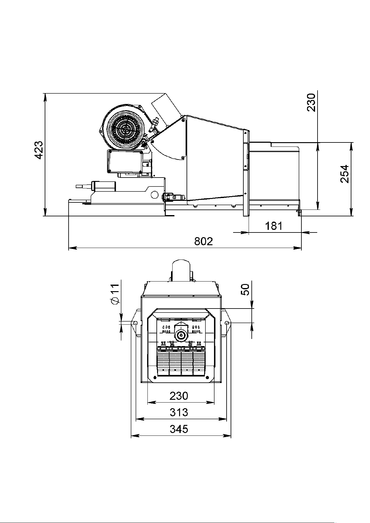
Burners of «AIR PELLET 60 KW» type (Picture 1) are intended for burning wood fuel
pellets in water-heating boilers with a nominal heat output of up to 60 kW.
Picture 1. Overall and mounting dimensions of the burner

5
The design of the boiler on which the burner is installed shall meet the following
requirements:
– the boiler shall be adapted for burning biomass, and its internal flow channels
shall have full capability to exchange heat and exhaust emissions;
– the combustion chamber shall have dimensions allowing to install and remove the
burner;
– the boiler’s door shall have a hole with a size of 260х240 mm, the thickness of
the boiler’s door shall be not more than 100 mm; get a hold of the manufacturing plant for
the boiler and obtain the advice, if required;
– the design of the boiler shall ensure the opening of the boiler’s door with a burner
for ash removal and cleaning. If the boiler’s door is too narrow for opening along with the
burner, the additional hinge straps shall be installed;
– if there is insufficient vacuum in the boiler (less than 5 Pa), it is required to install
the fan exhauster to remove burnt gases;
– the boiler-house where the burner is installed shall correspond with all the acting
local norms and rules;
– the boiler shall be located in such a way to ensure enough room for cleaning the
burner and removing ash from the boiler and the chimney. If the flue gas temperature at the
boiler outlet is less than 120 ° C, there is a risk of condensation of water vapor in the
chimney.
CAUTION! It is prohibited to use the burners for other than the purpose
specified as well as make any design changes of the burner without consent of the
manufacturer.
1.2.
Performance Data
The basic performance data of the burner is described in Table 1
Table 1.
Parameter
Value
Heat power (adjustable), KW
40…60
Fuel Characteristics:
diameter, mm
length
calorific value, KW•h/t
poured density, kg/m3
water content,%
ash content,%
6…8
3…5 of diameter
4700…5100
СА 650…670
kg/m3
8…10
Са 0,5
Power voltage, V
220
Power consumption, KW:
Firing mode
Working mode
not more 2,5
not more 1,5
Burner size LхWхH, m
0,86х0,42х0,34
Burner weight, kg
70
6
1.3.
Delivery Set
The standard delivery set for the burner is described in Table 2
Table 2.
Burner as an assembly
1 ea.
Burner control unit with sensor set and connecting wires
1 set
Flexible heatproof tube for connecting feeder to the burner
2 ea.
Burner case
1 ea.
Operation Manual
1 ea.
1.3.1.
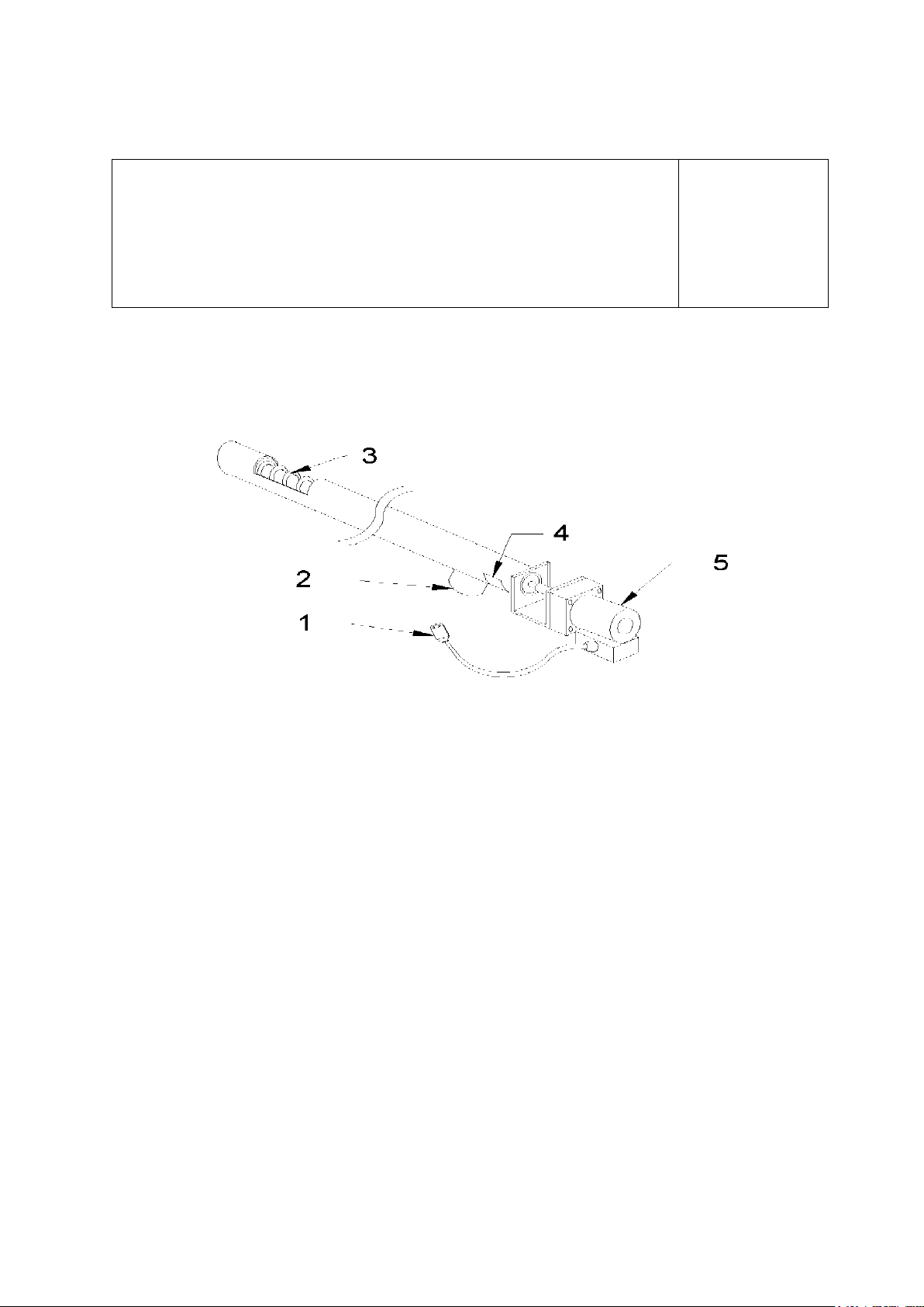
Screw Feeder
The screw feeder is intended for supplying pellets from the bunker to the burner. It
consists of the following elements:
Picture 2. Screw Feeder
1 – power cord; 2 – pellet outflow tube; 3 – pellet intake holes; 4 – safety cutoff; 5 – engine.
The screw feeder is connected to the burner with using a special hose made of
fusable material what ensures safety factor and prevents from inverted flame. With the help
of the mounting kit the screw feeder is fastened to the wall, bunker or ceiling depending on
installation area conditions. Picture 3shows correct location of the screw feeder towards the
horizon and the burner. It is necessary to meet the following recommendations during
installation and operation process:
– pellet intake hole shall be located upward vertically, and nothing should cover
(overlap) it;
– pellet outflow tube shall be located downward vertically;
– screw feeder shall be located towards horizon at an angle of 30-45°;
– horizontal distance between the pellet outflow tube of the screw feeder and the
burner pellet receiver tube shall be not less than 200 mm, at the same time, the hose for
hooking up the screw feeder and the burner shall not be slacking or having curves of more
than 30°, this will ensure unobstructed supply of pellets.

7
Picture 3 – Screw feeder installation example
CAUTION! Hose for hooking up the screw feeder and the burner shall
correspond with UL 94-HB fire-resistance.
1.4.
Operation Concept and Configuration
1.4.1.
Burner Components
The burner includes the following components:
– burner housing;
– trailing furnace grates;
– fuel firing system;
– burner with ceramic ejector nozzle;
– pellet supply system with driving gear;
– driving gear for furnace grates;
– pressurized air fan;
– electric system.
The burner housing is the basic unit, also serving as the base for the equipment
installed inside, including the trailing furnace grates and the ignition system.
The combustion chamber has the air injection holes inside.Their diameter is selected
in such a way to ensure the open air flow makes possible the optimal air dosing in the volume
required for the optimal burning of pellets.Primary air enters through the pumping holes
located in the trailing elements of the grate.
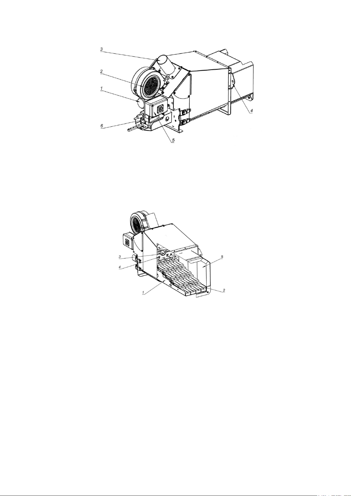
The design of the burner and its basic elements are shown on Pic. 4-5.
8
Picture 4 – Burner Design
1 – screw feeder driving gears; 2 – air supply fan; 3– hole for pellets supply from the bunker;
4 – flange for attaching the burner; 5 – housing for mounting electrical part; 6 – driving gear system of
movable grate bars;
Picture 5 – Burner combustion chamber design
1 – removable grate module, 2 – movable grate bars,3 – screw feeder of pellet supply, 4 –
heating elements of the ignition system, 5 – refractory lining.
CAUTION! The manufacturer reserves the right to incorporate changes into the
design, configuration, and software of the burner. Due to frequent upgrade of the
product some of presented below examples may insignificantly vary from the reality,
and this fact, however, does not impact on safety factor as well as proper operation
of the boiler and the burner.

9
1.4.2.
Operation Concept
The fuel located in the bunker is supplied by screw feeders to the burner and further to
the grate system, where it ignites as a result of contact with the elements of the ignition
system.
The air pumped by the fans goes further through the ejector openings of the grate
directly to the supplied fuel, as a result of which a flame rises and is directed horizontally to
the combustion chamber of the boiler.
The fuel remnants burn out in the ceramic pipe in the burner outlet tube. Hot air from
the burner goes further through channels of the boiler’s heat exchanger heating the water
that is the main heat carrier. Air is supplied exclusively in a volume required for clean
combustion, and its flow is monitored by the controller.
The electronic controller is monitoring the proper progress of the fuel supply and
combustion process. It controls the working cycle of the boiler: regulates supply of air to the
burner; regulates speed of fuel supply by screw feeders; controls water temperature and
exhaust emissions to the chimney; controls pumps operation and maintains the temperature
preset on the boiler. The burner is operating based on measurements coming from sensors:
gas temperature in the chimney, as well as water temperature in the boiler. Once the boiler
reaches the preset temperature the controller will automatically switch off the burner. In
addition, the controller plays a very important informational role displaying boiler operation
parameters as well as some emergency situations. Servicing of the boiler and the burner is
quite power-operated, but, however, it does not mean that the user is free from monitoring
the instructions and directions displayed on the controller.
CAUTION! The burner is able to work only with software of ТМ AIR automatic
equipment. Replacement of the controller with another one might result in failure of
the boiler and the burner as well as will result in loss of warranty. The way of
servicing the controller, its installation and hookup is described in detail in the
operation manual for ТМ AIR automatic equipment.
1.4.3.
Marking and Sealing
Each burner is accompanied with a manufacturer’s plate that contains the following
minimum information:
– full name and location of the manufacturer, and, if required, his authorized
representative;
– the unit’s purpose;
– marking with the national mark of conformity in accordance with Item 24 of the
Technical Regulations for the Safety of Machinery and Equipment;
– designation of the series or type;
– serial number (if available);
– year of manufacture (the year when the manufacturing process was completed).
1.4.4.
Packaging
Products are shipped in closed packaging, and the elements themselves are protected
with air-bubble film.
10
The technical documentation of the burner is always inside the box, and a bill of
lading is on the outer side. Products should be transported only in the original packaging,
thus eliminating the possibility to damage the units.
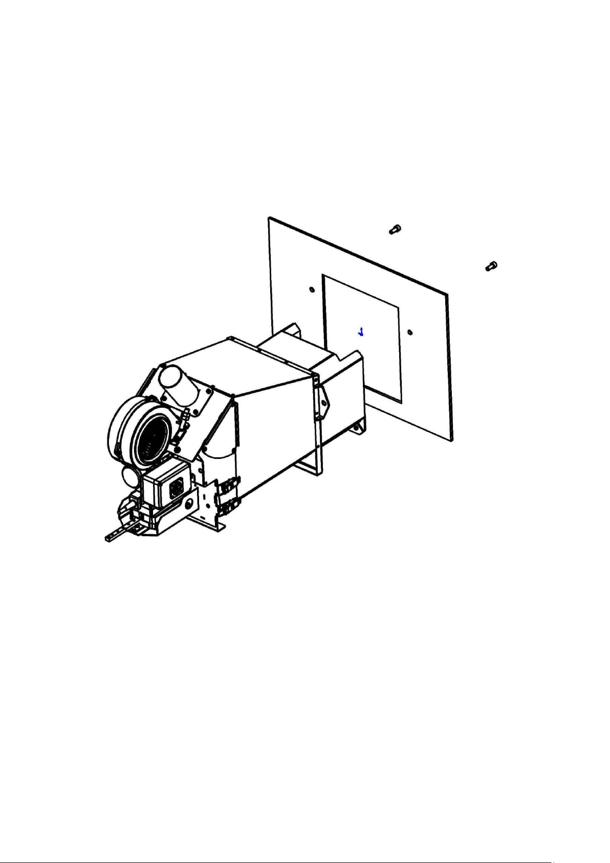
2.
INSTALLATION
The burner is mounted in such a way to have the furnace in the combustion chamber
and the burner is fastened with bolts using mounting holes located on the burner (Picture
6). If required, installation can be carried out using adapter flange as well as with use of
noncombustible, sealant material.
Picture 6 – Burner Installation
CAUTION! If there is a mounting seat stipulated by the manufacturing plant,
then the burner is installed on it in accordance with the documents delivered along
with equipment.
3.
BURNER OPERATION
3.1.
Operating Restrictions
The boiler room in which the burner is installed shall be equipped with exhaust
ventilation ensuring air flow at least 5 volumes of air in the boiler room for one hour.

11
3.2.
Preparation of the Unit for Putting into Operation
Prior to the first commissioning of the burner it is required to:
– verify proper installation and fastening of: the boiler, fuel tank, screw feeder and the
burner;
– check measuring devices for accurate installation;
– connect all electric cables and sensors to the controller, and connect the controller
to the in-house electrical network;
– check “idle” operation of all functions of the controller and the equipment installed;
– fill the bunker with pellets;
– check operation of the screw feeder.
3.3.
Startup of the Boiler with the Burner
The first commissioning of the boiler with the installed burner is always done by the
technician in the presence of a user. User’s presence is necessary to get familiar with
proper and safe service of the boiler as well as for correct setting up the corresponding
operation parameters on the boiler.
In order to start the boiler along with the burner it is required to take the following
steps:
– put all valves installed on the equipment in working position;
– set the required temperature on valves and radiator thermostats;
– close all boiler’s doors and covers of fuel tanks;
– switch on power supply for the burner and the controller;
– the further sequence of startup operation depends on the control system modification
and is described in detail in the Instruction for the control system.
CAUTION! The method of programming the controller and its service is
described in the Instruction for the control system.
If there is a necessity to change parameters set up on the controller it is required to
follow the procedure described in the Instruction for the control system.
3.4.
Burner Stop
The sequence of the burner stop depends on the control system modification and is
described in detail in the Instruction for the control system. It is not recommended to switch
off the power supply of the controller.
3.5.
Actions in Emergency Situations
In case of a burner failure it is required to take the following steps:
– switch off the power supply of all boiler units;
– turn off the power to the controller on the burner;
– disconnect the flexible pipe connecting the burner with the screw feeder (if required);
– unscrew the bolts fastening the burner with the boiler, move the burner away and
clean the boiler inside off the operational contamination;

12
– mark the boiler with the plate "FAULTY – DO NOT SWITCH ON";
– report to the management of the enterprise about the failure;
– ascertain the reason of the failure;
– if it is the simple failure, it can be eliminated on your own using technical services or
technical department of the enterprise. This Operation Manual includes the list of such
failures.
CAUTION! Intervention in such systems as: electrical, electronic and
mechanical is unallowable.
– If it is the serious breakdown, contact an authorized service center or use the
damage claim and contact the burner manufacturer.
4.
TECHNICAL MAINTENANCE
4.1.
General Instructions
Throughout the entire lifecycle of the boiler and the burner the user shall perform
routine cleaning as well as periodic inspections, and preservation of all units. They also
include periodic annual checks of chimneys.
4.2.
Safety Measures
Basic principles and recommendations to follow while operating the boiler with the
burner «AIR PELLET 60 KW»:
– Individuals who got familiar with the Operation Manuals for the boiler, the burner,
and the controller as well as with all possible threats can be allowed to operate this system.
CAUTION! Requirements as to hookup and operation of the boiler are
described in the technical documentation.
– It is prohibited to use the burner with a faulty seal of the mounting plate. In case of
smelling carbon monoxide from the outside of the boiler it is required to immediately turn off
the burner and restore the tightness of the seal.
– If it is necessary to carry out work inside the boiler, always turn off the burner and
wait for about 20 minutes to ventilate and cool off the combustion chamber.
– While performing a control (visual) test of the burner operation that might require
even a brief inspection of the combustion chamber, when opening the door one shall always
stand on the side of the door so as not to get a burn of the face and body with hot air. Do not
open the furnace doors with the burner installed!
– Do not touch the burner during its operation. Touching hot elements of the burner
with bare hands might result in the burn!
– When cleaning, always use protective gloves. Caution! To perform this work one
should not use the tools that could damage the equipment installed in the ejector tube of the
burner (grates, ignition system, etc.).
CAUTION! During the boiler and the burner operation, it is strictly forbidden to
drop hands into the elements of the screw feeder and the bunker with the fuel. This
might result in severe damage to the hands.
– Do not touch electrical wires or live electrical equipment. In case of such necessity,
it is always required to switch off the power supply to the whole system (boiler-burner-screw

13
feeder).
– The electrical system of the whole complex of the boiler with the screw feeder and
the burner shall have an effective protection system ("grounding / zero"). Sockets of all used
electrical connections must have a "zero" contact.
– It is prohibited to store flammable and explosive materials and liquids in the
immediate vicinity from the operating burner.
– Always follow the controller’s instructions correctly and properly. Especially in case
of "emergency situation" appearance and alarm.In such a case the procedure for
extinguishing the boiler (the burner) should be immediately applied, and the switched off
boiler shall be marked with the plate "FAULTY – DO NOT SWITCH ON".
CAUTION! Methods of behavior in emergency situations were described in a
separate section of this Manual.
– Protection against flame ingress into the screw feeder and the bunker is an elastic
polyurethane pipe provided by the manufacturer of the burner. Having overheated the pipe
melts what results in displacement of the hole and the cut-off of the pellet feed into the
burner. This is an effective form of protection against fires in fuel. It is forbidden to use
substitutes of the above mentioned pipe.
– It is strictly forbidden to use a defective burner or the burner with faulty equipment.
Re-commissioning of the burner is allowed after troubleshooting.
– Information and warning signs are placed on the whole system of the boiler with the
burner.
– During the operation of the boiler with the burner, always follow the principle of
“limited confidence” and carefully monitor the readings of the installed measuring-and-
recording equipment.
CAUTION! The information that is displayed on the controller is very much
important.
– All technical devices that are part of the boiler and the burner system shall undergo
a systematic technical inspection to the extent required by the acting normative documents.
This requirement is a guarantee for the safe use of these devices.
– In each emergency situation, immediately turn off the burner and the boiler, and
mark with the plate "FAULTY – DO NOT SWITCH ON".
– Each such a situation shall be reported to the relevant services of the enterprise
that are obliged to respond to the situation.
4.3.
Burner Maintenance Procedure
The burner maintenance procedure includes two main phases:
– current maintenance;
– periodic technical maintenance.
4.4.
Current Maintenance
The current maintenance includes the system of the following measures and actions:
– to keep the complex of the boiler – the burner – the screw feeder – the bunker, as
well as the installed equipment properly clean;
– current removal of contaminants in the burner nozzle;

14
– current elimination of minor operational problems on all the installed units (for
instance, replacement of a safety fuse in the controller, cleanup of the screw feeder, fixing of
a seal "burner – boiler", cleaning of the holes forcing the air into the burner);
– carrying out of all the current activities associated with maintaining the proper
operation of the burner;
– ongoing monitoring of the controller operation as well as operation of the
measuring-and-recording equipment.
4.3.1.
Periodic Technical Maintenance
In addition to current activity, it is the user’s responsibility to perform all periodic
technical inspections of the boiler, the burner, the screw feeder, the bunker, the installed
units and the chimney.
Inspection of the boiler and the fume extraction plant shall be carried out in
accordance with the schedule presented in the technical documentation for the boiler.
Within the framework of the periodic technical inspections it is required to perform:
– Monthly maintenance. Clean the burner outlet chamber from dirt and clean the air
intake openings. Monitor the controller operation. Check connections of the tank, screw
feeder, and the burner. In case of loose connection, it is required to tighten.
– Quarterly maintenance. Clean the internal space of the blower fans of the burner
with a vacuum cleaner.Check the fastening of the burner to the boiler, and in case of
detecting loose connection, it is required to tighten. Clean the heating elements of the
ignition system. Check, clean, and tighten the sensor connections. Check the fastening of
the screw feeder, clean the feed openings, and evaluate the correct operation of these units.
Check the cooling system of the burner.If leakage is detected at the joints, they shall be
fixed. Clean the controller with a vacuum cleaner, and check the operation of all its working
functions. Eliminate all reported operational problems, and make a list of the required spare
parts for replacement during the annual maintenance.
– Annual maintenance (best at the end of the heating season when the boiler is off).
Perform thorough inspection of the whole complex of the burner, screw feeder, and a fuel
tank.Perform thorough inspection of all control units and elements responsible for the
burner operation. Remove all the sensors and clean thoroughly all the joints. Check the
condition of the electrical installation of the entire burner complex and eliminate all the
identified problems.
Check the drives of the screw feeder and the moving grates. Add oil to the
gearboxes, if required. Clean all air injection holes in the trailing grates with a vacuum
cleaner. Unscrew the fans, clean them inside, and clean with a vacuum cleaner. Check the
mechanical functionality of the burner and confirm the readiness of all control elements.
Paint the cover of the burner complex, if required.Protect all sockets from adverse factors
that might occur in the boiler room.
CAUTION! Immediately prior to start of the heating season, a mechanical test
shall be carried out for all the units. This should be done after completion of the
annual boiler maintenance.

15
4.5.
Functionality Test
Burner functionality is checked with the help of the following sequence of actions:
– visual review in order to make sure there are no any mechanical defects, impurities,
then check fasteners and connecting wires for reliability;
CAUTION! If required, replace damaged parts or send for repair, remove dust,
impurities, screw attaching bolts as well as connecting ports.
– connect the burner to the control unit;
– when in manual mode, check operation of the internal screw, fan, and the heating
element;
– make sure there are no abnormal noises, sounds, etc. the internal screw rotates
anti clockwise, the fan is operated within the full range from 1% to 99%;
– if there are any discrepancies you shall get a hold of the service center and invite
the specialist.
CAUTION! The heating element shall be tested with the fan running only.
4.6.
Engineering Certification
The procedure, scope, and periodicity of the engineering certification of the product
and its components are in accordance with the current normative documents.
4.7.
Storage Instructions
The burner and its components shall be stored indoors or under the shelter excluding
direct atmospheric precipitation. Spare parts shall be stored in the closed premises. The
burner is delivered from the manufacturing plant after the preservation with the duration of
protective coatings of 12 months. At the end of the effective period of preservation of the
manufacturing plant or on long storage (more than 6 months) the burner shall be put into
long-term storage. All unpainted surfaces shall be coated with anti-corrosion grease.
Preservation shall be carried out at a temperature of not lower than +15 °Сand relative
humidity not exceeding 70 %. The units arriving for preservation shall be free of corrosion
damage to the metal and without damage to the paint and varnish coatings. Surfaces that
are subject to preservation shall be cleaned, degreased, and dried. Lubricants required for
preservation shall be consistent with those for the specified shelf life.
Depreservation is carried out by washing off the preservative coating.
5.
CURRENT REPAIR
5.1.
General Instructions
Normal operation of the burner requires only routine maintenance, cleaning, and
implementation of the necessary inspections. However, sometimes there are cases of
irregularities in the proper operation of the boiler and the burner. During the initial
operational period this is mainly caused by inability to properly operate the controller and the
boiler. But there are also problems for technical reasons. Below are the possible failures and
troubleshooting methods.

16
5.2.
Safety Measures
When carrying out repairs follow safety precautions described in Item 4.2 of this
Manual, safety rules, as well as requirements to repair of boilers that also include
requirements for the burner repair.
5.3.
Potential Failures and Troubleshooting Practice
Table 3 includes simple failures the user faces very often and the user is allowed to
fix such failures by his own efforts.
Table 3.
Failure
Potential Reason
Troubleshooting Method
Burner does not start
burning
Lack of fuel
1. Fill the bunker and screw feeder with fuel
pellets.
2.
Remove error on the controller by pressing
«Stop» button.
3.
Repeat firing process by pressing «Start»
button.
Igniter failed
1. Get in touch with the manufacturer or service
company.
Large amount of bottom ash in
the burner firebox
1. De-energize the burner.
2. Let it get cool up to the safe temperature (lower
45°С).
3. Clean the firebox thoroughly to restore passing
ability of air channels.
Internal screw does not work
1.Check the network for stable power supply.
2.Check fastenings of the internal screw with
gearbox.
3. Check electric wiring (contacts) on gearbox and
burner connector.
Boiler overheat
(overheat detector
light is
ON on the
controller panel)
Rise of maximum temperature
for heat carrier heating
-up in
central heating circuit
1. Press «Stop» button on the controller.
2. Let the boiler get cold.
3. Define the reason for overheat and take
measures to eliminate it.
Damage of
temperature sensor
Damage in chain of the heat
carrier temperature sensor
1. Get in touch with the manufacturer’s service
company if the data on error is not annulled after
pressing «Stop button.
2. Replace the sensor
Failure
Potential Reason
Troubleshooting Method
Damage in chain of the outgoing
gas temperature sensor
1. Get in touch with the manufacturer’s service
company if the data on error is not annulled after
pressing «Stop button.
Burner smokes, soot
appears
Extra amount of fuel in
comparison with air. Burner
firebox is filled with bottom ash
1. Let the burner get cold, and clean the burner
firebox to restore passing ability of air channels.
2. Adjust amount of fuel and fan rpm.
Burner firebox is filled
with bottom ash too
often
Fuel of poor quality is used
1. Change operation mode of the cleaning unit
(See Controller
Manual).
2. Change the fuel supplier.
The examples described above do not exclude other reasons that might result in a

17
malfunction of the burner’s proper operation as well as operation of other units associated
with the burner.These are only examples that can be useful for the user in resolving
emerging problems.
6.
TRANSPORTATION AND STORAGE
The burner and the equipment are always delivered to the user on pallets, in the
original sealed factory packaging that protects the product from potential damage during
transportation.
Always read and take into consideration information signs located on boxes, some
elements might be fragile and shock-sensitive as well as sensitive to the influence of
unfavorable atmospheric conditions. It is forbidden to throw, move sharply, and jam boxes
with heavy elements.
In case of detecting the damaged boxes it is required to open them in the presence of
the supplier and inspect the products located inside. In case of detecting significant damage
to the products (dents, cracks, damage to the control cabinet, etc.) it is necessary to
immediately draw up the damage certificate for the supplier and notify the manufacturer
about this fact.
CAUTION! All shipments shall be always checked at the moment of receipt and
in the presence of the supplier.
Burners are not intended for stockpiling as well as for storage in places not suited for
this purpose within the period exceeding 12 months. Their storage location shall meet the
following requirements:
– on shelves, only in the original, factory and labeled boxes;
– only in dry, closed, and ventilated premises;
–in rooms at a temperature of 5…40 °C and humidity not exceeding 50%
– in premises free of aggressive materials or chemical agents.
CAUTION! It is forbidden to store or stockpile the products in the open air.
Corrosion or damages caused by improper storage conditions are beyond the claim
for replacement. In case of storing burners longer than 12 months they shall be
checked (inspected) by the manufacturer’s technicians who have to confirm the
completion of this inspection in the product warranty letter (this relates exclusively to
the products stored in warehouses or points of sales).
7.
DISPOSAL
Burners of «AIR PELLET 60 KW» type are safe for the environment and follow all the
requirements of norms associated with cleanliness of exhaust as well as exhaust emission
to the atmosphere. Cardboard packages of the delivered units can be used for firing or sent
to the old paper stock. Steel construction and the burner housing do not pose any threat to
the environment as well as the screw feeder housing, and the tank. Once the working life is
over they are handed over for scrap recycling. All used electrical equipment elements are
made of plastic (for example, protective elements, handle, tubes, etc.) and they shall be
sorted and handed over for recycling or processing.

18
8.
WARRANTY
The item of warranty in this context is the pellet burner of «AIR PELLET 60 KW» type.
The manufacturer guarantees failure-free operation of the burner for the period of 12 months
starting from the date of the first startup (putting into operation), but not longer than 24
months from the date of manufacture and on conditions that the unit is operated properly
and undergoes technical maintenance in a timely manner.
Warranty for heating elements is granted for the period of 1 year. Two-year warranty
for the burner is valid only if the burner firebox is cleaned off ash and noncombustible
residues regularly enough for the purpose of avoiding deformation and damage of the
combustion chamber.
Warranty is valid:
– only on the territory of the country where the burner was sold;
–if a user has not incorporated (made) any changes into the burner configuration and
construction;
– if the works on putting the burner into operation and adjustment of burner operation
parameters have been carried out by the authorized representative of the manufacturing
plant.
Warranty does not cover defects occurred through:
– user’s fault due to improper assembling of the burner;
– user’s fault due to violation of operation rules for the burner and the boiler;
– lack of reasonable diligence;
– loss of burner’s delivery set items;
– willful damage;
– repair (or attempt to repair) performed by an unauthorized individual;
– power outages;
– use of low quality fuel;
– for burners that were installed and adjusted by a company or individual that are
non-authorized by the manufacturing plant;
– natural disasters (lightning strike, fire, flood, submergence, etc.).
CAUTION!DEFORMATION AND BURNING-OUT OF THE COMBUSTION
CHAMBER AND CLEANING AGITATOR CAUSED BY UNTIMELY SERVICE ARE NOT
CONSIDERED TO BE MANUFACTURING FLAW AND NOT COVERED BY WARRANTY
OBLIGATIONS.
The list of authorized representatives of the manufacturing plant can be found on
website of LTD «Bioprom Company Kharkov» bioprom.ua.
Company-manufacturer address: 126/1, Plekhanovskaya Str., Kharkov city, 61037,
Ukraine

19
Warranty Ticket
Burner Model
Product Number
Date of Sale
Name of Company-Seller
Date of installation/putting into operation
Owner Details Installer Name and
Signature Name _
Tel _
City _
Street/House
# ___________
For all issues relating to warranty and post-warranty service, please feel free to
contact us at the address of: 126/1, Plekhanovskaya Str., Kharkov city, 61037, Ukraine.
Telephone of Service Center: + 38 (095)654-67-19; + 38 (098)232-52-15.
http://bioprom.ua/
Е-mail – no12serv[email protected]om.ua.

20
Record on warranty repair
Defect description: ______________________________________________________
Reason for failure: _______________________________________________________
______________________________________________________________________
Repair work performed: ___________________________________________________
______________________________________________________________________
Name of repair company: _________________________________________________
License # ____________ Expert ________________ Repair date _________________
stamp
Table of contents
Popular Burner manuals by other brands

Riello
Riello RLS 160/EV Installation, use and maintenance instructions

Riello
Riello RS 28/M Installation, use and maintenance instructions

True Induction
True Induction TI4B user guide

Riello
Riello RG1RKD Installation, use and maintenance instructions

Weishaupt
Weishaupt WG20 Series manual

Carolina Cooker
Carolina Cooker M116672 owner's guide


AESYS
AESYS TurboFire II Installation, operation and maintenance manual

IKEA
IKEA GRILLSKÄR manual

baltur
baltur TBL 1000 ME Instruction manual for installation, use and maintenance

Riello Burners
Riello Burners P 200 P/G Installation, use and maintenance instructions

WLD-TEC
WLD-TEC powerjet instruction manual

Riello
Riello RDB 3.2 BX 32/50 Installation, use and maintenance instructions