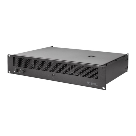
bittner XR 4000 DSP User manual

ã
Bittner-Audio
O
Amplifier
Series XR DSP
Installation &
Operations Manual

2
ã
Bittner-Audio
BITTNER Installation &OperationsManual
Power Amplifier Series XR DSP Installation &OperationsManual
Bittner -Audio
©2006Bittner-Audio.All RightsReserved.
Bittner-AudioreservesspecificationprivilegesInformationinthismanualissubjecttochangewithout noticeorobligation.
Version 1.0
TABLE OF CONTENTS
O.............................................................................................................................................................1
Declarationsof Conformity.......................................................................................................................2
Caution....................................................................................................................................................2
Installation...............................................................................................................................................3
Front Panel..........................................................................................................................................3
Rear Panel..........................................................................................................................................3
AirVentilation and Cooling Requirements............................................................................................4
Power Connection...............................................................................................................................4
LED Indicators.....................................................................................................................................4
System Monitoring –AliveContact...........................................................................................................5
SXL Data Port..........................................................................................................................................5
RS-485 Ports...........................................................................................................................................5
Power Switching / Remote On/Off-Switching............................................................................................6
Audio Connections...................................................................................................................................7
Audio InputConnectors........................................................................................................................7
Input Gain Controls– DigitalPotentiometers........................................................................................7
Balanced and unbalanced Inputs, Levels.............................................................................................8
Grounding............................................................................................................................................8
DecibelExplanation.............................................................................................................................8
Loudspeaker Output Connectors..........................................................................................................8
Operation Modes.....................................................................................................................................9
Stereo Operation.................................................................................................................................9
ParallelOperation................................................................................................................................9
Bridged Operation (Mono)....................................................................................................................9
DSP Processor......................................................................................................................................10
1.1 DSP ControlInterfaceSXL with SXLWeb interface:.....................................................................10
2. DSP Control over RS-485:.............................................................................................................11
Channelmeasurement...........................................................................................................................12
Warranty Terms& Conditions................................................................................................................13
TechnicalSpecifications.........................................................................................................................14
Frequency Response Full Power...................................................................................................14
Congratulationsand thank you for your decision buying an amplifierfromBITTNER. Theseamplifiersare
famousfor theirveryhigh reliability.Advanced technicalsolutionsand abigamount ofelectronicsecurity
circuitsallowa use with great efficiency.
DECLARATIONS OF CONFORMITY
Bittner-Audiohereby declaresthatthisproduct is in accordance with the following standards:
EMC Regulation 89/336/EEC (ElectromagneticCompatibility)
EN-55013 (Radio Disturbance, Emission
EN-55020 (Electromagneticimmunity)
CAUTION
To reduce the riskofelectricalshock, do not removethe cover. There are no user serviceablepartsinside,
referallservicing to qualified personnel.Replace fuses onlywith same type. Avoiddamaging the AC plug or
cord. Itcan potentially causing ashock hazard. The unitshouldonlybeconnected to anAC power supplyof
the correct voltage.

3
ã
Bittner-Audio
BITTNER Installation &OperationsManual
To reduce the risk offire or electricalshock, do not expose thisappliance to rain or moisture. Do not usethis
unitin damp areasor near water.
The amplifier mustbe adapted slowlyto extremetemperature changes.Theseextremechangescan cause
moisture developmentinside the amplifierthatcan cause failure and /or electricalshock.
Though the amplifiersfromBITTNER are quite simpleto operate and arecovered by asolidchassis,
improper usecan be dangerous.Someofthe amplifiers can put out veryhigh voltagesand asizable current
at frequenciesup to 30kHz.
NEVER isolate the ground ofthe AC power cord (the non-fused earthed protectiveconductor) to eliminate
hum-problems. See chapter ‘Grounding’.
Alwaysuse safe operating techniques!Incompetent and improper servicing can voidthe warranty.
Withthe in-buildDSP processor extended functionality isavailable:
-Level Control
-Input routing ofthe input channelsto the two amplifierchannels
-10-Band Equalizer
-Dynamics(Limiter/Compressor/Gate)
-Delay
-Cross-Over
-Up to 100 presets
INSTALLATION
Upon unpacking, pleaseinspect the amplifier.Ifyou find any damage, notifyyour supplier immediately. Be
sure to savethe carton and allpacking materialsincaseyou haveto send the product to the supplier.
Please use only the originalfactorypacking.If the shipmentcarton isunavailable, contactBITTNER-Audio to
obtain a replacement.
The amplifierswill mount instandard 19-inch rackshaving sufficientdepth. For the installation 4standard
boltsshouldbe used. For proper mechanicalstability the use ofsupporting rack slideson the bottomofthe
amplifierisnecessary.
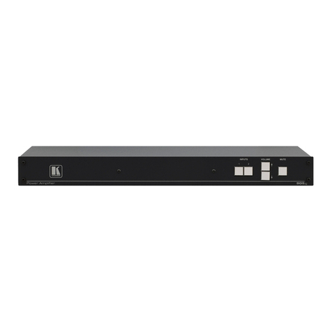
Front Panel
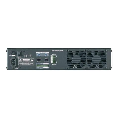
Rear Panel
(image can differ slightlyfromtheactual version)

4
ã
Bittner-Audio
BITTNER Installation &OperationsManual
AirVentilationandCoolingRequirements
The amplifierisequipped withaforcedair-cooling systemwithvariablespeed and temperature controlled
fansto guarantee lowoperating temperature and minimalventilation noise. The seriesXRamplifiersare
equipped with fourelectronicallycontrolled fans,twoat the front side and twoat the rear side. The air flow
takesplace from the rearofthe amplifiertothe front.
Becausethe XRSeries areclassHamplifiers,overheating isnot anissueunderregular conditions.The
amplifier will heat up only slightly even under fullpower.
In caseany heat sink becomestoo hot, the temperature sensoropenstherespectiveoutput relay,
disconnecting the outputload fromthe particular channel.After cooling downto the appropriate operating
temperature the relay contactsare closed again automatically.
It isimportant to haveadequate airventilation space behind the amplifier to allowaproper airflow.In case
the amplifier ismounted into aclosed rack, do notcover the frontof the rack withdoors.Using rackswith a
closed backside, use fanson the rear rack panel (air flow to the inside of the rack).
PowerConnection
The power amplifier mustbe connected onlywith the attached three-wire
safety power cord with protectiveconductor (non-fused earthed
conductor). Thisamplifier ismade for usewith the mainsvoltage labeled
on the back of the amplifier only.
Check the label on the back panelofthe amplifierforthe appropriate
voltage. The voltage version ofthe amplifier ispreset and cannot be
changed. Make sure the voltage ofyour mainsoutletiscorrect. Damage
causedby connecting the amplifier to improper AC voltage voidsthe
warranty.
The power fusesare located on the back panelofthe amplifier and can be
accessed from the outside.Use only the appropriate fusesaslabeled.
After properlymounting and connecting the AC cord and the audio
connections,the unit can be switched on. The POWER indication LED
indicatesthat the amplifier hasbeen turned on.
LED Indicators
The amplifierisequipped with the following LEDson the front panel:
LED COLOR FUNCTION
ONLINE green Indicatesthatthe unitisconnected toan SXL unitor via RS485 network
STANDBY yellowIn controlmode (SXL, RS-485, RemoteControlVoltage) thisLED
indicatesthat amplifierisin standby mode (power switched off).Manual
power switch overridesthisseting. When standby mode isoverriden
manually, both STANDBY and POWER ledsare ON.
POWER CH1 Green Indicatesthatamplifierchannel1 ispowered up.
CLIP CH1 Red Indicatesthatthe input isoverloaded. The LED starts illuminating as
soon asthe signalis0.5 dBunder fullpower.
SIGNALCH1 Green Indicates,that signal reachesthe output stage ofthe amplifier.
PROTECT CH1 Red ThisLED will lightup assoon a protection circuithasbeen activated or
if one ofthe output relayshasbeen activated. When the amplifier is
switched on, thisLED illuminated forapproximately 1.5seconds.
POWER CH2 Green Indicatesthatamplifierchannel2 ispowered up.
CLIP CH2 Red Indicatesthatthe input isoverloaded. The LED starts illuminating as
soon asthe signalis0.5 dBunder fullpower.
SIGNALCH2 Green Indicatesthatsignalreachesthe outputstage of the amplifier.
PROTECT CH2 Red ThisLED will lightup assoon a protection circuithasbeen activated or
if one ofthe output relayshasbeen activated. When the amplifier is
switched on, thisLED illuminated forapproximately 1.5seconds.

5
ã
Bittner-Audio
BITTNER Installation &OperationsManual
SYSTEM MONITORING –ALIVE CONTACT
The XRSeriesamplifiersare equipped with the ‘AliveContact’. The contactislocated on the rear panelof
the amplifier and isaGPI contact closure that indicatesthe generaloperation mode ofthe amplifier.Itis
designed asa 3-pole contactclosure that can be used in the ‘open’ mode orthe ‘closed’ mode:
Alive Contact active:indicatesthat the amplifier isworking innormal conditions
Alive Contactinactive: indicatesthat the amplifier isnot working properly:it isshut
down by the protection circuit, overheated etc.or generally
switched off
Thiscontact closure isthe simplest form ofremote systemmonitoring of the amplifierwithout
establishing aremote controlnetwork and provideseasysystemsurveillance at avery
economicallylevel. The ‘Alive Contact’ can also be integrated into a media controlnetwork as
aGPI contact closure to trigger eventuallyneeded other control procedureslike backup amplifier (spare
amplifier) switching.
SXL DATA PORT
The XRSeriesamplifiersare equipped with the SXLdata port to connect the BITTNER SXLProgrammable
ControlInterface to the amplifier. To connectthe BITTNER amplifiersto the SXL unit all amplifiers must have
a unique address. The addressisselected on the DIP switch at the rear panel ofthe amplifier and can be set
to 1 to8:
Example:Address1: ON,ON,ON,ON,ON,ON
Address2: OFF,ON,ON,ON,ON,ON
After anaddress change the amplifier must be re-powered to activatethe changes!
Up to 16 amplifier channelscan beconnected to the SXL. The 16amplifier channelscan becombined from
stereo, 4-channeland 8-channelamplifiers.
When the amplifier isconnected to the SXL, itisautomaticallyrecognised by the SXLunitand the
appropriate Link LED on the SXLfront panelindicates‘ON’. IfRS-485 communication (see nextchapter) is
not used the sametime, permanent communication withthe SXLunitisalsoindicated by fastblinking green
LED (TX) on the amplifier’srear panel.
The modelnumber and other featuresofthe amplifiercan be verified on the SXLfront panelLCD inthe
group ‘AMP’. Thegroup ‘AMP’ can be browsed using the LEFTand RIGHT keyson the SXLfrontpanel.
For more detailsplease refertothe OperationsManual ofthe BITTNERSXL.
RS-485 PORTS
The XRSeriesamplifiersare equipped with twoparallelRS485 ports,PORT1 and PORT2 via RJ-45
connectors.Using one ofthe portsasan input and the second asan output, aRS-485 network with bus
topology can be established easily.
To connect the amplifier to the controlcomputer, the RS-485 addressmustbeset with the DIP switchesat
the rear panelof theamplifier. Up to 64 addressescan be selected.

6
ã
Bittner-Audio
BITTNER Installation &OperationsManual
RS485 isa multi-pointcommunicationsnetwork with up to 32 driversand 32 receiverson
a single (2-wire) busand are ableto withstand "data collisions" (buscontention)
problemsand bus fault conditions. RS485 extendsthe commonmode range forboth
driversand receivers in the so-called "tri-state" mode.
RS-485 Connector Pinout:
The RS-485 interface on the XRSeriesamplifiersisahalf-duplextransceiver with one
single bus(2-wire) for transmitting and receivingdata on the same bus.
RS485 PORTconnector (RJ45):
Pin1 RS485GND
2 NC
3 DATA+
4 DATA-
5 DATA-
6 DATA+
7 NC
8 RS485GND
Pin 3 and 6and pin 4and 5 carrythe samesignal.
Note: DATA+is pulledvia 10k resistor to +5V volts andDATA- is pushed toRS485GND
via 10k in idle state.
RS-485 Indicators
TwoLED indicatorsare activewhilereceiving data(red=RX)and transmitting data
(green=TX) over RS485.
RS-485 Address
In the RS-485 controlmode the amplifier isidentified by itsaddress.Usethe DIP
SWITCH ADDRESS 1-6 settingsto set the RS-485 node addressfrom 01 to 64:
Example:Address00: ON,ON,ON,ON,ON,ON
Address01: OFF,ON,ON,ON,ON,ON
The amplifier mustbe re-powered before the addresschange is activated !
For further information to connect the DSP controlsoftware, refer to the chapter ‘DSP
ControloverRS-485’.
POWER SWITCHING /REMOTE ON/OFF-SWITCHING
There are three optionsto switch the amplifier on and off.
Option 1 –ManualSwitching:
The amplifiercan be switched on manually byswitch placed on back panel. When
amplifierisswitched on manually, itcan't be switched on/offremotely. Manualswitch
overridesremote switch control. To switch the amplifierremotely,the manual switch must
be inOFF position.
Option 2 –Remote Switchingwith 12VDC-Control Voltage:
The PHOENIXterminalblockisused for remote switching with acontrolvoltage (12VDC). Terminal1and 2
are used asthe controlvoltage input. Supplying the controlvoltage to these terminalswillswitch the amplifier
ON. After adelay ofone secondinternallythe terminals4and5ofthe PHOENIXterminalblock willbe fed

7
ã
Bittner-Audio
BITTNER Installation &OperationsManual
with the controlvoltage.Theseterminalsare intended to be connected toterminals1and 2ofthe next
amplifierfor sequentialpower switching. Up to 10 units canbedaisy-chained thisway for sequentialpower
switching.
The controlvoltage must be supplied untilthe last amplifier in the daisy-chain setup isswitched on. Ifno RS-
485 controlisused, the controlvoltage can be thenremoved. When RS-485 isused, 12 VDC muststay
connected to supplyamplifiersalsoinstandby mode. The amplifiersPowerOn/Standby mode isthen
controled over RS-485 - see section ‘DSP Controlover RS-485’.
By supplying the inverted DC controlvoltage to terminal1 and 2, theamplifier willbe switched off(turn +/- to
-/+).Asfor the powering-up procedure, the controlvoltage isinternallyfed to the terminals4and5for
supplying the controlvoltage to the next daisy-chainedamplifier.For the switching-off sequence, no delay is
engaged and all amplifiersare switched ofat thesamemoment.
The controlvoltage/amperage is12VDC and the necessary current is80mA during switching on the amplifier
or inStandby mode. The needed current iszero assoonasthe amplifier issupplied by itsownpower
supply.
RemoteSwitching PHOENIXConnector:
1 – AmplifierSwitching POSITIVE terminal
2 – AmplifierSwitching NEGATIVEterminal
3 – Control Voltage supplyforsequentialswitching POSITIVE terminal
4 – Control Voltage supplyforsequentialswitching NEGATIVEterminal
Option 3 –Remote Switching from controlunit
When connected online to controllersBITTNER SXLor viaRS-485 network to PCwith the appropriate DSP
controlsoftware, the amplifier canbe switched on and put to Standby mode by anyofthe controllers.
AUDIO CONNECTIONS
Alwaysturnoffthe amplifier before making any connections.Asanadditionalprecaution by switching the
amplifier on forthe first time,turnthe audioattenuatorsdown during powering up.
AudioInput Connectors
The XRSeries amplifiersare equippedwith twoXLRinput connectorsand parallelPHOENIXconnectors,
both on the rear panelofthe amplifier. The audioinputsofthe seriesXRamplifiersare electronically
balanced. The XLR connector isa combined XLR / TRS jack connector.
Standard
XLR Connector
Pinout:
1 =Ground, Shield
2 =Signal positive
3 =Signal negative
Input GainControls – Digital Potentiometers
The XRSeriesamplifiersare equipped with wear-free digitalrotary level
controlswith rotary stepsforeach channelat the rear panelofthe
amplifier.
Ifthe unitisconnected online to the BITTNER SXLcontrolunit or to
another controldevice (computer) via the RS-485 port,the gaincan be
controlled fromthe connected controlunit.Anychangesinthe gain
settingsfromthe controldevice willoverride the settings on thelocal
PHOENIXConnector
Pinout:
Pin 1 = Signal+CH1
Pin 2 =•Signal – CH 1
Pin 3 =•Ground CH 1 +CH 2
Pin 4 =•Signal +CH 2
Pin 5 =•Signal – CH 2

8
ã
Bittner-Audio
BITTNER Installation &OperationsManual
digitalpotentiometers.Only changing the potentiometer position willoverride the lastsettingsfromthe
controlunit. In short, lastchange alwaysreplacesprevioussetting no matter whether itcamefromcontrol
unit ordigitalpotentiometer.
Attention: the last gain setting is always stored in the amplifier’s memory. Turning the amplifier on, the stored
gain setting is used. The setting of digital potentiometeris used after startup only when the potentiometer is
at -90dB position. This case amplifier starts with -90dB gain.
BalancedandunbalancedInputs, Levels
The amplifiercan accept unbalanced or balanced lines.For optimumperformance and with longer cable
runs,usebalanced lineswhenever possible. The driving device shouldbe equipped with abalanced output.
With short cables inside one rack the issue isnot thatcritical.
Abalanced connection providesexcellent noiseimmunity frominterference and ground loops.Abalanced
audioconnection isaccomplished by using adifferentialpairofsignals,isolating themfromground. While
theseconnectionsprovide great noiseimmunity, care mustbe taken when connecting balanced and
unbalanced equipmenttogether.
Grounding
The chassisgroundofthe amplifier isconnected with the ground ofthe AC power cord (thenon-fused
earthed protectiveconductor).Assoon asseveral devicesare connected with each other inasignalchain,
aground loop iscreated. Ground loopsare caused when current flows fromthe analog ground plane of one
piece ofequipment to the ground plane ofanother. Acompensating current travelsbetweenthe different
deviceson the shieldsof the audiocables.Make sure all audioconnectionsare appropriatelygrounded and
shielded to avoidhum-problems.NEVER isolate the ground ofthe AC power cord(the non-fusedearthed
protectiveconductor).Thisisa violation ofthe lawand dangerous!
Decibel Explanation
Adecibelisalogarithmicscalecommonlyused to expressdifferencesinsignallevels.It isusefulinaudio
because itcan expressawide dynamicrange with relativelysmallnumbers(or asmallmovement on a
meter), and it moreclosely matcheshowwe perceivesound.
The measurement quotedindB describesthe ratiobetweenthe quantityoftwolevels,the levelbeing
measured and areference. The absolute quantity ofthesignalisnot relevant.Thismeansthat decibelsare
alwayscomparing one quantity to another. For example, when wemeasure gainindB, weare comparing
the output level tothe input level.
To describe an absolute value, the reference point mustbe known. There are different reference points
defined.
dBV representsthe level compared to 1Volt RMS:0dBV =1V withno reference toimpedance.
dBu representsthe levelcompared to 0,775 VoltRMS on an unloaded, open circuit.
dBm representsthe power levelcompared to 1 mWatt.Thisisalevelcompared to 0,775 VoltRMS across a
600 Ohmload impedance.
1dBV equals+2.2dBu, +4dBu equals1.23 Volt RMS,the reference level of-10dBV isthe equivalent to a
level of-7.8dBu.
Headroomisameasure (usuallyindB) ofhowmuch higher the peaksofasignalcan be compared to the
nominallevelwithout clipping. That is,it comparesthe peak level(involtsRMS) to the nominallevel(involts
RMS). The differencebetween the two (in dB) isthe headroom.
LoudspeakerOutput Connectors
The impedance ofthe connected loudspeaker line couldbe between2Ohmsand16Ohms.The minimal
connected loudspeaker impedance is2Ohms.In the
BRIDGE operation mode the minimalconnected
impedance is4 Ohms.
Output wiring
Useheavygauge wire for speaker connections.The
greater the distancebetweenthe amplifier and the
speakers,the larger the diameter the wire shouldbe.

9
ã
Bittner-Audio
BITTNER Installation &OperationsManual
Thiswillminimize power lossesacrossthe wire and improvedamping ofthe speaker. Wire thickness
specifications(gauges) get larger asthe wire getsthinner. So a14-gauge wire isthicker than 18-gauge wire.
Speaker cablescanbe connected to the PHOENIXconnectorsor tothe 4pinNEUTRIK SPEAKON
connectors. The PHOENIXconnectorsare preferable designed for fixedinstallations.
Speakon Connector Pinout:
1 +positiveterminal
1 negativeterminal
2 +(not connected)
2 (not connected)
It ispossibleto useboth connectionsparallel at the sametime.Pleasepay attentionthatthe “+”poleofthe
PHOENIXconnectorscorrespondsto the„1+” pin ofthe SPEAKON connector ofthe corresponding channel.
The impedance ofthe connected loudspeaker line couldbe between2Ohmsand16Ohms.The minimal
loudspeaker impedance is2 Ohms.In the operation mode BRIDGEthe minimalimpedance is4 Ohms.
OPERATION MODES
On the rear ofthe amplifier three different operationmodescan be selected on the DIP-Switch panel:
STEREO,PARALLEL and BRIDGEDMODE.
The amplifier mustbe re-powered before the mode change is activated !
StereoOperation
For stereo operation, turn the amplifier off and set the mode select switchesto the STEREO position. In this
mode, both channelsoperate independentlyofeach other, with theirinput attenuatorscontrolling their
respectivelevels. Thus, an input signalat Channel1 producesan amplifiedsignalatthe outputofChannel1,
while an inputsignalatChannel2 producesan amplified signalatthe outputofChannel 2.
The minimumload impedance for stereo operationis2 Ohmsper channel.
The loudspeaker could be connected to the SPEAKONconnector and / or to the PHOENIXconnectorsat the
same time.A mixedconnectionisalso possible.
Parallel Operation
For paralleloperation, turnthe amplifier off and set the mode selectswitcheson the PARALLEL position.
Both amplifiersare then driven by the signalofchannel1. Output connectionsare the same asfor the stereo
operation.
Onlythe input of channel1isactive,the input ofchannel2isout ofcircuit. Input attenuator 1controlsboth
channellevels
The loudspeaker couldbe connected to the SPEAKONconnector and /or to the screwterminals.Amixed
connection isalso possible.
BridgedOperation(Mono)
Both amplifierchannelscan be bridged to create apowerfulsingle-channel mono amplifier.Useextreme
caution when operating inbridged mode.To bridge the amplifier,turn the amplifieroff and set the rearmode
select switchesto the BRIDGED position.
Onlythe input of channel1 isactive,channel2 isout of circuit. Only attenuator 1 remainsactive and controls
both channelsgain. Connect the speakersacross the “+”terminalsofboth PHOENIXconnectors.The
‘positive’ poleof the loudspeaker shouldbe connected to the “+”terminal of channel1, the ‘negative’ poleto
the “+”terminalof channel2.
The recommended load impedance for the bridged operation is8Ohms.Minimalimpedance for the bridged
operation is4 Ohms.

10
ã
Bittner-Audio
BITTNER Installation &OperationsManual
DSP PROCESSOR
The SeriesXR amplifiersare equipped with an internalDSP processor. With the internalprocessor extended
functionality isavailable:
-Level Control
-Input routing ofthe two amplifierchannels
-10-Band Equalizer
-Dynamics(Limiter/Compressor/Gate)
-Delay
-Cross-Over
-Up to 100 stored presets
Twoway ofcontrolling the internal DSPare available:
1. the control interfaceBITTNERSXL, connected tothe amplifier via control network
2. the DSP software installed on a computer, connected via RS-485 to the amplifier
1.1 DSP Control Interface SXLwithSXLWebinterface:
(See alsochapter ‘SXLData Port’.) The DSP can be controlled with the Web Interface of the BITTNER SXL
ControlInterface.The amplifiermustbe connected to the SXLunitbyribbon cableand asthe next step the
SXLunitmustbe connected to the controlling PC overthe Ethernet controlnetwork to establishaccessto
the built-in-sxlweb server.
When the SXLunitisaddressed viaWeb browser, the DSP controlpage ofthe Web Interface isavailable
and allfeaturesofthe DSPare accessibleviathe web interface (see image below).
The availableSXLpresets(settingsofallamplifiers,16channelsandSXL) are called Configurations(Cfg)
and can be savedand recalled fromtheSXL’sinternalmemory.
Asignalgenerator isalsoavailablewithinthe DSPfunctionalityand can be used aspilottone generator
(loudspeaker line test) or astest tone generator for measurementsetc.
Note:Controlsthatare notusedwiththe specified amplifier modelare disabled i.e. notused and notavailable.
screen shot ofthe DSP control over the SXL webinterface
Note: Toobtain access to theSXL web interface, the user mustfirst log-in. Default name/password is:

11
ã
Bittner-Audio
BITTNER Installation &OperationsManual
Username: sxl
Password: 11111
Please refer for more detailed information tothe SXL Manual.
2. DSP Control overRS-485:
(See alsochapter ‘RS-485 Ports’.) The DSP canbe controlled alsoviathe RS-485 port on therear panelof
the amplifier. For thiscontrolmode the appropriate software mustbe installed on acomputer. The computer
mustbe connected to the RS-485 port. The RS-485interface waschosen to be ableto control the unit
remotelyover longer distances.Ifthe unitshouldbe controlled locally,any standard Interface fromUSB or
RS-232 to RS-485 can be used to getthe computer connected to the RS-485 port of the amplifier.
Assoon asthe amplifierisconnected to the controlcomputer,the unitcan be manuallyconnected (menu
‘Devices’) or scanned automatically.
screen shot ofthe DSP control with PC software, over the RS-485 interface
After connecting to the amplifier’sDSP, the shown sub windowscan be opened andpositioned freelyon the
main window.With the preset functionality the current settingscanbe stored. Up to 100 DSP presetscan be
stored and recalled.
Note: Presets can'tbe stored / recalled while amplifier is in Standby mode.
The DSP control software forPC (WindowsTM) isavailablefrom BITTNER Audio.

12
ã
Bittner-Audio
BITTNER Installation &OperationsManual
CHANNEL MEASUREMENT
The SeriesXRamplifiersmonitor input/output valuesofeveryswitched-on channel.Allofthe valuesare
availablevia SXL controlunit and the vitalonesalsovia RS-485 interface.
XR amplifier monitors:
-Input level
-Output peak voltage
-Load impedance (output signal at least 30 dB under nominal power must be present)
-Output peak current
-Output power
-Headroom
-Heatsink temperature
Detected are Protect,Clip,Output Open and Output Short conditions.
WhenSXL control unit isconnected, Open/Short threshold inohmscan be defined byuser.
Via RS-485 interface vitalmonitors/detectorsare available - protect,temperature,load impedance.

13
ã
Bittner-Audio
BITTNER Installation &OperationsManual
WARRANTY TERMS &CONDITIONS
Bittner-Audio (the manufacturer) warrantsthisproduct to be free fromdefectsinmaterialsand workmanship.
Shouldany part ofthisequipment be defective, the Manufacturer agreesto repairor replace any defective
part free ofcharge (excepttransportation charges)foraperiod ofthree yearsfromthe date ofthe original
purchase.
Warranty service iseffectiveand availableto the originalpurchaser only.
To obtainservice under thiswarranty, the productmust, on discoveryof the defect,be properlypacked and
shipped to the nearestBittner-Audiodealer. The party requesting service mustprovide proofoforiginal
ownership and date ofpurchase ofthe product.
Ifthe warranty isvalid,Bittner-Audiowill, without charge for partsor labor, either repairor replace the
defectiveparts.Without avalidwarranty, the entire costofthe repairisthe responsibility ofthe product’s
owner.
The warranty doesnot cover defectsor repairsneeded asa result of:
1. Damage caused by abuse, accident, ornegligence.
2. Damage caused by any tampering, alteration, or modification of the productor itscomponents.
3. Damage caused by failure to maintainand operate the product instrict accordance to the written
instructionofthisoperatingmanual.
4. Damage caused by repairsor attempted repairsby unauthorized persons.
5. Damage caused by fire, water and other naturalevents.
6. Damage caused by operation on improper voltages.
BTTNER-Audio

14
ã
Bittner-Audio
BITTNER Installation &OperationsManual
TECHNICAL SPECIFICATIONS
Model XR 1500XR 2000XR 2500XR4000
NumberofChannels 2222
Class HHHH
Power at8+8 Ohm(1kHz,0.1%THD 2x430W2x620W2x810W2x1240W
Power at4+4 Ohm(1kHz,0.1%THD) 2x750W2x1000W2x1250W2x2070W
Power at2+2 Ohm(1kHz,0.1%THD) 2x1050W2x1400W2x1600W2x2800W
Power BridgeMode8Ohm(1kHz,1%THD) 1300 W1850 W2200 W3880 W
Power BridgeMode4Ohm(1kHz,1%THD) 1800 W2400 W2900 W4000 W
FrequencyResponse Full Power
20Hz-20kHz(dB) 0/-0.3dB 0/-0.3dB 0/-0.3dB 0/-0.3dB
THD +N(%) 0.02 0.02 0.02 0.02
Inputs electronically
balanced
electronically
balanced
electronically
balanced
electronically
balanced
Input Impedance 12 kOhm12 kOhm12 kOhm12 kOhm
InputSensitivity +6dBu +6dBu +6dBu +6dBu
InputClipping +22dBu +22dBu +22dBu +22dBu
MinimalLoadImpedance 2Ohm2Ohm2Ohm2Ohm
MinimalLoadImpedanceinBridgeMode 4Ohm4Ohm4Ohm4Ohm
ChannelSeparation >85dB >85dB >85dB >85dB
Signal to NoiseRatio(20Hz–20kHz) 106 dB 107 dB 107 dB 110 dB
Weight 24 kg 24 kg 25 kg 25 kg
InstallationHeight 2RU 2RU 2RU 2RU
InstallationDepth 454 mm454 mm454 mm454 mm
Table of contents
Other bittner Amplifier manuals
