FMS EMGZ411 User manual

Operating Manual EMGZ411
Digital microprocessor controlled
Tension Measuring Amplifier
Version 2.04 05/04 sd
This operation manual is also available in german, french and italian.
Please contact your local representative.
Diese Bedienungsanleitung ist auch in deutsch, französisch und italienisch erhältlich.
Bitte kontaktieren Sie die Vertretung im zuständigen Land.
Ce mode d'emploi est également disponible en français, en italien et en allemand.
Veuillez contacter la représentation locale.
Queste manuale d’installazione è disponibile anche in lingua italiano, francese e tedesco.
Vogliate cortesemente contattare la locale rappresentanza.
© by FMS Force Measuring Systems AG, CH-8154 Oberglatt – All rights reserved.

Operating Manual EMGZ411
2
1 Safety Instructions
1.1 Description conditions
a) High danger of health injury or loss of life
Danger
This symbol refers to high risk for persons to get health injury or loss life. It has to be
followed strictly.
b) Risk of damage of machines
Caution
This symbol refers to informations, that, if ignored, could cause heavy mecanical damage.
This warning has to be followed absolutely.
c) Notice for proper function
Notice
This symbol refers to an important information about proper use. If not followed,
malfunction can be the result.
1.2 List of safety instructions
Proper function of the tension measuring amplifier is only guaranteed with the
recommended application of the components. In case of other arrangement, heavy
malfunction can be the result. Therefore, the installation instructions on the
following pages must be followed strictly.
Local installation regulations are to preserve safety of electric equipment. They are not
taken into consideration by this operating manual. However, they have to be followed
strictly.
Bad earth connection may cause electric shock to persons, malfunction of the total
system or damage of the measuring amplifier! It is vital to ensure that proper earth
connection is done.
The processor board is mounted directly behind the operation panel. Improper
handling may damage the fragile electronic equipment! Don’t use rough tools as
screwdrivers or pliers! Don’t touch processor board! Touch earthed metal part to
discharge static electricity before removing operation panel!
Some contacts on the power supply are under 110V resp. 230V tension! Mortal
danger! Disconnect power supply before open the housing!

Operating Manual EMGZ411
3
Table of contents
1Safety Instructions ....................................................................................2
1.1 Description conditions 2
1.2 List of safety instructions 2
2Definitions..................................................................................................4
3System components...................................................................................4
4System description ....................................................................................5
4.1 Functional description 5
4.2 Force sensors 5
4.3 Electronic unit EMGZ411 5
5Quick installation guide............................................................................7
6Dimensions.................................................................................................8
6.1 Dimensions: Variant for insert card support block (EMGZ411) 8
6.2 Dimensions: Variant with separate housing (EMGZ411.E) 8
7Installation and wiring..............................................................................9
7.1 Mounting and wiring of the measuring amplifier 9
7.2 Mounting the force sensors 9
7.3 Wiringdiagram:Variant forinsert cardsupport block (EMGZ411) 10
7.4 Mounting the distance sensor 12
8Operation .................................................................................................13
8.1 View of the operating panel 13
8.2 Calibrating the measuring amplifier 14
8.3 Additional settings 16
8.4 Setup of the correction input 17
9Serial interface (RS232)..........................................................................20
9.1 Wiring diagram: RS232 interface 20
9.2 Command list 20
9.3 Read parameter 21
9.4 Write parameter 22
10 Parametrization.......................................................................................23
10.1 Parameter list 23
10.2 Schematic diagram of parametrization 24
10.3 Description of the parameters 25
11 Trouble shooting......................................................................................32
12 Technical data EMGZ411 ......................................................................33

Operating Manual EMGZ411
4
2 Definitions
Offset: Correction value for compensation of the zero point difference. Thanks to the
offset, it is ensured that a force of 0N will generate a signal of 0V exactly.
Gain: Amplification factor for the measuring signal. Use of proper value will set the
measuring range of the sensor exactly corresponding to the signal output range (0...10V).
Strain gauge: Electronic component that will change its resistance while its length has
changed. Strain gauges are used in the FMS force sensors for acquisition of the feedback
value.
3 System components
The EMGZ411 consists of the following components (refer also to fig. 1):
Force sensors
• For mechanical/electrical conversion of the tension force
• Force measuring bearing
• Force measuring roller
• Force measuring journal
• Force measuring bearing block
Electronic unit EMGZ411
• For supplying of the force sensors and amplifying of the mV signal
• With operation panel for parametrization
• Analogue correction input for processing varying wrap angles, etc.
• Interface RS232
• Interface CAN-Bus
• For mounting into insert card support block EMGZ555959 (by mounting into control
cabinet)
• Mounted in separate housing (EMGZ411.E)
• Integrated power supply (by using separate housing)
• Supports connection of an external feedback display
(Italic components as variant or option)

Operating Manual EMGZ411
5
4 System description
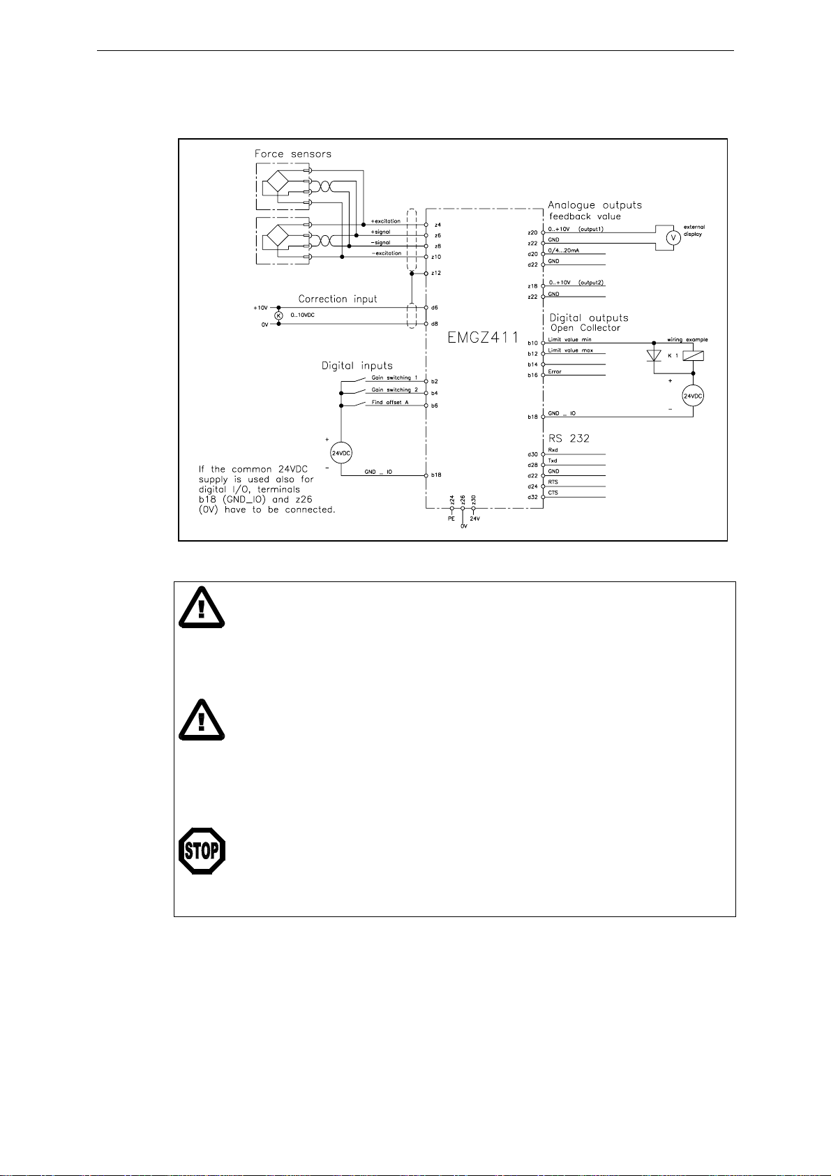
fig. 1: Basic structure of the EMGZ411 tension measuring amplifier E411002e
4.1 Functional description
The force sensors measure the tension force in the material and transmit the measuring
value as a mV signal to the electronic unit EMGZ411. The electronic unit amplifies the
mV signal depending on configuration. The resulting feedback value is shown in the
display in [N]. In addition, the feedback value is provided at the analogue outputs and can
be evaluated by an analogue instrument, a PLC or equivalent devices.
4.2 Force sensors
The force sensors are based on the flexion beam principle. The flexion is measured by
strain gauges and transmitted to the electronic unit as mV signal. Due to the wheatstone
wiring of the strain gauges, the measured value is according also to the power supply. So,
the force sensors are supplied from the EMGZ411 by a very accurate power supply.
4.3 Electronic unit EMGZ411
Common
The electronic unit contains a microprocessor to handle all calculations and
communications, the highly accurate sensor power supply and the signal amplifier for the
measuring value. As operation interface it provides 4 keys, 4 LED’s and a 2x16
characters display in the front of the electronic unit. All inputs are saved in an EEPROM.
The electronic unit has no jumpers or trimmers to keep most accurate long-time and
temperature stability.
There can be connected one or two force sensors to the electronic unit.
Strain gauge amplifier
The strain gauge amplifier provides the highly accurate 4V power supply. A highly
accurate, fixed difference amplifier rises the mV signal up to 10V. This signal will be fed
to the A/D converter. The microprocessor then does all application-specific calculations
with the digitized measuring value (such as offset, gain, low-pass filter, limit switches,
etc).
Using digital inputs, the amplifier can be switched easily between 3 different gain
parameters (for ex. to process different operating conditions). There is no reconfiguration
required to switch the gain parameters.
If a measuring point has a varying wrap angle or other non-linear measuring values, gain
may be adjusted using a linear or a cosine correction.

Operating Manual EMGZ411
6
Interface
As standard, the electronic unit supports an RS232 interface. As an option, there is an
additional board with CAN-Bus interface available.
fig. 2: Block diagram of the electronic unit EMGZ411 E411003e

Operating Manual EMGZ411
7
5 Quick installation guide
• Check all your requirements such as:
– configuration of the analogue outputs (signal level)?
– gain switching required?
– correction input required?
– linking by serial interface etc.?
• Draw your final wiring diagram according to the wiring diagrams (refer to „7.3 Wiring
diagram variant for insert card support block“ / „7.4 Wiring diagram variant with
separate housing“)
• Install and wire all your components (refer to „7. Installation and wiring“)
• Parametrize and calibrate the measuring amplifier (refer to „8.2 Calibrating the
measuring amplifier“)
• Put system into operation; proceed a test run with low speed
• If required, do additional settings (refer to „8.3 Additional settings“)

Operating Manual EMGZ411
8
6 Dimensions
6.1 Dimensions: Variant for insert card support block (EMGZ411)
fig. 3: Dimensions of the variant using insert card support block (EMGZ400 series).
The support block EMGZ555959 has to be ordered separately. E411004us
If the electronic unit should be mounted into a 19“ rack, a multipoint plug is used instead
of the support block.
6.2 Dimensions: Variant with separate housing (EMGZ411.E)
fig. 4: Dimensions of the variant using separate housing (option, EMGZ400.E series)
E411005e

Operating Manual EMGZ411
9
7 Installation and wiring
Caution
Proper function of the tension measuring amplifier is only guaranteed with the
recommended application of the components. In case of other arrangement, heavy
malfunction can be the result. Therefore, the installation instructions on the following
pages must be followed strictly.
Caution
Local installation regulations are to preserve safety of electric equipment. They are not taken
into consideration by this operating manual. However, they have to be followed strictly.
7.1 Mounting and wiring of the measuring amplifier
Variant for insert card support block (EMGZ411)
The insert card support block can be mounted in a control cabinet. Wiring to the terminals
is done according to „7.3 Wiring diagram: Variant for insert card support block“ (fig. 5).
The electronic unit then will be inserted into the insert block. It will be locked by a stop
hook (fig. 3).
Variant with separate housing (EMGZ411.E)
The housing can be mounted in a control cabinet or directly beside the machine. All
connections are led through glands to the screw terminals and connected according to
„7.4 Wiring diagram: Variant with separate housing“ (fig. 6 and 7).
7.2 Mounting the force sensors
Mounting of the force sensors is done referring to the FMS Installation manual which is
delivered together with the force sensors.
Wiring to the terminals of the electronic unit is done according to wiring diagram (fig. 5
resp. 6).
Notice
Connecting the shield of the signal cable to the measuring amplifier and to the force
sensor may cause ground circuits which may interfere the measuring signal massively.
Malfunction can be the result. The shield should be connected only to the measuring
amplifier. On the „force sensor side“, the shield should stay open.

Operating Manual EMGZ411
10
7.3 Wiring diagram: Variant for insert card support block (EMGZ411)
fig. 5: Wiring diagram: Variant for insert card suppor block E411006e
Caution
Bad earth connection may cause electric shock to persons, malfunction of the total system
or damage of the measuring amplifier! It is vital to ensure that proper earth connection is
done.
Caution
The processor board is mounted directly behind the operation panel. Improper handling
may damage the fragile electronic equipment! Don’t use rough tools as screwdrivers or
pliers! Don’t touch processor board! Touch earthed metal part to discharge static
electricity before removing operation panel!
Danger
Some contacts on the power supply are under 110V resp. 230V tension! Mortal danger!
Disconnect power supply before open the housing!

Operating Manual EMGZ411
11
fig. 6: Wiring diagram: Variant with separate housing E411014e
fig. 7: Screw terminal arrangement on terminal board E411001e

Operating Manual EMGZ411
12
7.4 Mounting the distance sensor
If the measuring point operates with a varying wrap angle as it is found with winders or
unwinders with no intermediate roller (fig. 13), the actual wrap angle has to be
transmitted to the measuring amplifier. FMS recommends to acquire the actual reel
diameter with a distance sensor and to led the distance signal to the analogue correction
input (terminals d6 / d8 resp. 7 / 8).
It has to be ensured that the measuring axis of the distance sensor is straight radial to the
reel (refer to fig. 8).
Optical distance sensor CMGZ581934
FMS recommends to use the optical distance sensor CMGZ581934 because its accuracy
and signal output is adapted to the FMS tension measuring amplifiers and tension
controllers.
fig. 8: Mounting of the distance sensor CMGZ581934 E411012e
The distance sensor operates with the 3-beam-correction principle. It is considerable
insensible to secondary light and changes of the surface colour of the detected object. But
while mounting it must be ensured that the sensor is mounted in „horizontal“ position
(fig. 8).
The output signal is proportional to the reel radius: Small radius = small signal; large
radius = large signal.
Technical data distance sensor CMGZ581934
Type HT77MGV80, Infrared light 880nm
Measuring range 1000mm [40“]
Ø Measuring distance 800mm [32“]
Min. measuring distance 300mm [12“]
Max. measuring distance 1300mm [51“]
Resolution 0.2...30mm [.008...1.2“] depending on width of spot
Reaction time 10ms
Linearity 2%
Temperature drift 0.5mm / K [.01“ / °F]
Supply voltage 18...30VDC / 70mA
Temperature range –10...+60°C [14...140°F]
Protection class IP67

Operating Manual EMGZ411
13
8 Operation
8.1 View of the operating panel
fig. 9: Operating panel: Variant for insert card support block (EMGZ411) E411007e
fig. 10: Operating panel: Variant with separate housing (EMGZ411.E) E411008e

Operating Manual EMGZ411
14
8.2 Calibrating the measuring amplifier
Parametrizing the measuring amplifier
The following parameters have to be set resp. to be checked before the first calibration is
done (ref. to „10. Parametrisation“):
• Nominal force
• Unit of force
• Sensitivity
• 1 or 2 sensors
• Config. output 1
• Scale output 1
• Scale output 2
• Input correction (for the time being set to none)
Simulating Method (recommended)
The following instructions are referring to
a setup and calibration on-site. The
material tension will be simulated by a
weight (fig. 11).
• Connect the first force sensor
• Check, if a positive value is displayed
when loading the sensor in measuring
direction. If not, exchange terminals
z6 / z8 (resp. 2 / 3)
• If used, connect the second force
sensor
• Check, if a positive value is displayed
when loading the sensor in measuring
direction. If not, exchange terminals
z6 / z8 (resp. 2 / 3)
• Insert material or a rope loosely to the machine
• Adjust offset by activating the parameter function find offset A and pressing the ↵key
for 3 seconds (ref. to „10. Parametrisation“). The electronic unit calculates
automatically the new offset value.
• Load material or rope with a defined weight (fig. 11)
• Activate parameter function Calibration A. Input the force referring to the applied
weight (refer to „10. Parametrization“). The electronic unit calculates automatically
the new gain value.
• Quit calibration with Home key.
fig. 11: Calibrating the measuring
amplifier C431011e

Operating Manual EMGZ411
15
Mathematical method
If the material tension cannot be simulated, calibration has to be done by calculation. This
way of calibrating is less accurate because the exact angles are often unknown and the
effective mounting conditions, which usually deviate from the ideal, are not taken into
account.
• Offset adjustment has to be done as described under „Simulating method“.
• The Gain value will be calculated by the following formula and then inputted in the
parameter gain channel A (refer to „10. Parametrization“).
fig. 12: Force vectors in the FMS force measuring bearing C431012e
Definition of symbols:
αangle between vertical and measuring
web axis FBmaterial tension
βangle between vertical and FMF
Groller weight
γmaterial wrap angle FMmeasuring force resulting from FB
γ1entry angle of material FMeff effective measuring force
γ2exit angle of material n number of force sensors
δAngle between measuring web axis and FM
()
n
ckGainFeedba ⋅⋅
=2/sinsin 1
γδ

Operating Manual EMGZ411
16
8.3 Additional settings
Setting of the lowpass filters
The measuring amplifier provides 3 lowpass filters independently adjustable from each
other. They are used to prevent noise which is added to the signals. Signal variations
which are faster than the cut-off frequency are then suppressed. The lower the cut-off
frequency, the more sluggish the output signal will be.
The lowpass filters are configured by setting its cut-off frequency to an appropriate value.
The cut-off frequency is set in the parameter Lowpass display resp. Lowpass output 1 /
Lowpass output 2 (ref. to „10. Parametrisation“).
Notice
If the cut-off frequency is set to a value too low, the output signal will become sluggish.
It may be that the feedback value is no longer suitable for control loop applications. You
have to pay attention that the cut-off frequency is set to a suitable value.
Setting of the limit switches
The measuring amplifier provides 2 limit switches which can be tapped at the digital
outputs (terminals b10 and b12 resp. 27 and 28). The limit switches are actuated when the
feedback value exceeds (Limit value max.) resp. undershoots (Limit value min.) the force
values stored in parameters Minimum limit value resp. Maximum limit value.
Tapping of the limit switches is done according to wiring diagram (fig. 5 or 6).
Scaling of the analogue outputs
With default setting, the analogue outputs give the maximum signal (10V resp. 20mA)
when the nominal force of the sensors is reached. The output signal level can be
customized with the parameters Scale output 1 / Scale output 2.
Gain switching
If a measuring point is operated with varying measuring conditions (for ex. different
material paths), the gain factor may be switched between up to 3 values depending on the
material path. Switching is done using the digital inputs „Gain switching 1“ resp. „Gain
switching 2“. Therefore, the extra gain values have to be calibrated during setup too (ref. to
parameters Cal. gain 1 A / Cal. gain 2 A / Gain 1 channel A / Gain 2 channel A).
Tare function
If parameter Config. of key is set to TareA, pressing the ↓key will set the display and the
feedback value to zero. Therefore, variations of the display during retooling may be
compensated.
The original offset value remains in the measuring amplifier. If the ↓key is pressed
again, the original offset value is restored; display and output signal show the original
feedback value.

Operating Manual EMGZ411
17
8.4 Setup of the correction input
If the measuring point is operated with a varying wrap angle as it is found with winders
or unwinders (fig. 13), the effective measuring force FMeff is varying due to the geometric
relations between FBand FMeff (ref. to fig. 12). The variations do also appear when
material tension FBis constant.
fig. 13: Application with varying wrap angle E411011e
To get even though a constant value for tension feedback, the gain factor has to be
adjusted dynamically to the actual wrap angle during operation.
The measuring amplifier is able to do that correction. You can select between cosine
correction and linear correction. FMS recommends using the cosine correction because it
calculates the effective correction at any time. If the simulating setup of the cosine
correction is not possible, the linear correction may be used. However, the linear
correction has a certain inaccuracy due to its function principle. The maximum error can
be calculated. This allows to decide if the amount of deviation is allowed or not.
Transmission of the wrap angle signal
To transmit the actual wrap angle to the measuring amplifier, an analogue signal 0...10V
(from a distance sensor or PLC) is fed to the correction input (terminals d6 / d8 resp. 7 / 8).
However, the distance sensor (ref. to „7.5 Mounting the distance sensor“) detects the
actual reel radius ∆r but not the actual wrap angle ∆γ.
ar
∆
∆=arcsin
γ
If the wrap angle varies not more than 30° (∆γ≤30°), the relation between ∆r and ∆γis
almost linear. In that case the ∆r signal can be fed directly to the correction input.
If the wrap angle varies more than 30° (∆γ> 30°), the relation between ∆r and ∆γbecomes
non-linear. In that case the ∆r signal has to be converted to the ∆γvalue using a PLC or
special software.

Operating Manual EMGZ411
18
Variation of the gain factor in relation to the wrap angle
The gain factor is adjusted by a correction factor kdepending on the wrap angle γto
provide the correct feedback values in the display and at the outputs. If the measuring
amplifier is calibrated at γmin the correction factor kresults as shown in the following
diagram:
fig. 14: Correction curves for gain factor E411013e
Cosine correction (recommended)
The cosine correction calculates internally the effective correction based on three
reference points (k1, km, k2) and therefore it works very accurate. It is calibrated as
follows:
• Set arrangement to minimum wrap angle γmin (ref. to fig. 13). Calibrate gain and offset
as written in „8.2 Calibrating the measuring amplifier“.
• Set parameter Input correction to Cosine.
• Check the voltage signal of the distance sensor (should be approx. 0...3V). Proceed for
parameter function Cal. gain cos 1; the correction k1 (ref. to fig. 14) will be saved.
• Set arrangement roughly to medium wrap angle (ref. to fig. 13)
• Check the voltage signal of the distance sensor (should be approx. 4...6V). Proceed for
parameter function Cal. gain cos 2; the correction km (ref. to fig. 14) will be saved.
• Set arrangement to maximum wrap angle γmax (ref. to fig. 13).
• Check the voltage signal of the distance sensor (should be approx. 7...10V). Proceed for
parameter function Cal. gain cos 3; the correction k2 (ref. to fig. 14) will be saved.
Now the cosine correction is ready for operation. The measuring amplifier tracks now the
effective correction curve, depending on the radius signal of the distance sensor.

Operating Manual EMGZ411
19
Linear correction
If the three points k1, km, k2 can’t be reached during simulating setup, a linear correction
can be calculated. A straight line is centered to the effective correction curve by setting
the parameters Correction at 0V and Correction at 10V to appropriate values (fig. 14).
However, this procedure will cause a certain error. The maximum error emax appears at the
maximum wrap angle (γmax).
The linear correction is calibrated as follows:
• Set arrangement to minimum wrap angle γmin (ref. to fig. 13). Calibrate gain and offset
as written in „8.2 Calibrating the measuring amplifier“.
• Determine the following application data as accurate as possible referring to fig. 12:
Minimum wrap angle γmin = ________________ [°]
Minimum angle δ(at position γmin) δmin = ________________ [°]
Signal of distance sensor (at position γmin) Umin = ________________ [V]
Maximum wrap angle γmax = ________________ [°]
Minimum angle δ(at position γmax) δmax = ________________ [°]
Signal of distance sensor (at position γmax) Umax = ________________ [V]
• Calculate the following values (precision at least 5 digits):
4
sin
2
sin
2
sinsin
maxminmaxmin
min
min
γγδδ
γ
δ
+
⋅
+
⋅
=
m
k= ________________ [-]
2
sinsin
2
sinsin
max
max
min
min
2
γ
δ
γ
δ
⋅
⋅
=k= ________________ [-]
⎠
⎞
⎜
⎝
⎛−+
−
⋅=
∆m
k
k
k1
21
2
12= ________________ [-]
%100
2
max ⋅= ∆
kk
e= ________________ [%]
k
UUk
UP ∆
−
−
−
⋅−=
minmax
2
min0 1
1= ________________ [-]
0
minmax
2
10 1
10
P
UUk
P+
−
−
⋅= = ________________ [-]
• Set parameter Input correction to Linear.
• Store the P0value in parameter Correction at 0V.
• Store the P10 value in parameter Correction at 10V.
Now the linear correction is ready for operation. The measuring amplifier tracks now the
straight line (fig. 13), depending on the radius signal of the distance sensor. Maximum
deviation of the feedback value in relation to the effective material tension equals to emax.

Operating Manual EMGZ411
20
9 Serial interface (RS232)
The serial interface is operated for example by a personal computer as a kind of „question
and answer“ game: The PC sends a question resp. a command; the measuring amplifier
will send an answer back. If the answer is missing, the measuring amplifier or the
connection cable may fail.
9.1 Wiring diagram: RS232 interface
fig. 15: Wiring diagram RS232 interface E400001e
Reliable connection using maximum baudrate (9600) is guaranteed up to wire length of
10m. If the baudrate is reduced and/or good conditions prevail, considerably greater
distances can be bridged in some cases.
Connection to a PC etc. is done with a 9- or 25-pole Sub-D connector.
9.2 Command list
command answer purpose
ERR?<CR> XXXXXX<CR> read actual errors
Pos. 1...6 : Err1...Err6
Value of Pos. = 0 : No Err;
Value of Pos. = 1 : Err active
IDNT<CR> EMGZ411 V2.00 1198 10 characters type, fix
< Type > <Version> <S > 10 characters version, fix
4 characters serial number, fix
INRS<CR> PACC<CR> / FAIL<CR> initialize interface
(for ex. after loading of new
interface parameters)
REMR<CR> PACC<CR> / FAIL<CR> turn off remote mode
(enabling the keys on the
operating panel)
REMS<CR> PACC<CR> / FAIL<CR> turn on remote mode
(disabling the keys on the
operating panel)
VALS<CR> XXXXXX<CR> read feedback value
Table of contents
Other FMS Amplifier manuals