manuals.online logo
Brands
  1. Home
  2. •
  3. Brands
  4. •
  5. Black Line
  6. •
  7. Antenna
  8. •
  9. Black Line LTEfree 82252L User manual

Black Line LTEfree 82252L User manual

82252L
82254L
82259L
82262L
82352L
82354L
82359L
82362L
82300L
82372L
82379L
CB437
CB340
CB337
CB140
CB437A
CB340A
CB337A
CB140A
CB120
CB445
CB345
BREVETTI
PAT E N T E D S Y S T E M
Made in Italy
Livello d’uscita VHF 115 dBμV - UHF 120 dBμV o 123 dBμV
Output level VHF 115 dBμV - UHF 120 dBμV or 123 dBμV
Niveau de sortie VHF 115 dBμV - UHF 120 dBμV ou 123 dBμV
•
Guadagno VHF da 30 dB a 40 dB, UHF da 37 a 45 dB, regolabile 0-20 dB
Gain VHF from 30 dB to 40 dB, UHF from 37 to 45 dB, adjustable 0-20 dB
Gain VHF de 30 dB à 40 dB, UHF de 37 à 45 dB, réglable 0-20 dB
•
•DIP switch interno per la selezione della telealimentazione
Internal DIP switch for selection of the remote power supply
Commutateur DIP interne pour la sélection de l'alimentation à distance
Black Line
Codici
Code
Réf
Articolo
Article
Article
CENTRALINI A LARGA BANDA CON AMPLIFICAZIONE SEPARATA
WIDE BAND TV AMPLIFYING HEAD-ENDS WITH SEPARATED AMPLIFICATION
CENTRALES D’AMPLIFICATION LARGE BANDE AVEC AMPLIFICATION DISTINCTE
• NOTE PER L’INSTALLAZIONE
Emme Esse S.p.A. Via Moretto, 46 - 25025 Manerbio (BS) Italy
Tel. +39.030.9938500 r.a. Fax: +39.030.9380592 www.emmeesse.it e-mail: [email protected]
Notes for Installation / Remarques pour l’installation
Placez la centrale d’amplification dans un endroit sec et bien aéré.
Branchez les câbles au bloc terminal terre;
La centrale est fournie avec œillet pour la connexion
au terminale équipotentiel au sol.
Branchez les câbles d’antenne à leurs connecteurs
d ‘entrée de la centrale; fermez toutes les entrées inutilisées
avec la résistance à 75 Ω.
Connectez le réseau TV à la sortie OUT de la centrale’
et le mésureur de champ à la sortie TEST - 30 dB.
Réglez le signal TV.
Posizionare il centralino in luogo asciutto e ben areato.
Collegare i cavi alla morsettiera di messa a terra;
il centralino è provvisto di asola per la connessione
al terminale equipotenziale di Terra.
Collegare i cavi delle antenne ai rispettivi connettori
d’ ingresso del centralino; chiudere eventuali ingressi
non utilizzaticon resistenze a 75 Ω .
Collegare la rete TV all’ uscita OUT del centralino
ed il misuratore di campo all‘ uscita TEST – 30 dB.
Procedere alla regolazione del segnale TV.
Place the head-end in a dry aired area.
Connect the cables to the clamp grounding block;
The head-end is equipped with slot for the connection
to the ground unipotential terminal.
Connect the cables of the antenna to their input connectors
of the head-end; shut eventual unused inputs
with 75 Ohm resistors.
Connect the TV to the output OUT of the head-end
and the field meter to the test output - 30 dB.
Proceed with the adjustment of the TV signal.
• UTILIZZO DELLA TELEALIMENTAZIONE
Remove the lid of the upper part of the head-end while
untightening the 4 lateral screws.
Follow the aside table for input selection.
Position on ON the button matching the input to be remotely power supplied
(See connector No.3 on the input).
USE OF REMOTE POWER SUPPLY / UTILISATION DE LA TELE ALIMENTATION
Rimuovere dalla parte superiore del centralino il coperchio
svitando le quattro viti laterali.
Seguire lo schema sotto riportato per la selezione degli ingressi.
Posizionare su ON il tasto corrispondente all’ ingresso da tele-alimentare
(come da gura ES. sul connettore N° 3).
Retirer de la partie supérieure de la centrale le couvercle
en dévissant les quatre vis latérales.
Suivre le tableau ci-dessous pour la sélection des entrées.
Allumez la touche correspondant à l’entrée à télé-alimenter.
(Comme le montre la gure exemple sur le connecteur No 3)
Made in Italy
CENTRALINI A LARGA BANDA CON AMPLIFICAZIONE SEPARATA
WIDE BAND TV AMPLIFYING HEAD-ENDS WITH SEPARATED AMPLIFICATION
CENTRALES D’AMPLIFICATION LARGE BANDE AVEC AMPLIFICATION DISTINCTE
UNI EN ISO 9001:2008 n. 2878/0
This manual suits for next models

21

Popular Antenna manuals by other brands

Sea Tel 9797B-70 C-Band TX/RX Installation and operation manual

Sea Tel

Sea Tel 9797B-70 C-Band TX/RX Installation and operation manual

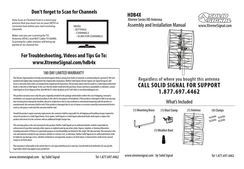
Solid Signal Xtreme HDB4X Assembly and installation manual

Solid Signal

Solid Signal Xtreme HDB4X Assembly and installation manual

RR Electronic DELTA 1000 S Mounting instructions

RR Electronic

RR Electronic DELTA 1000 S Mounting instructions

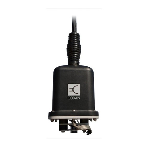
Codan 3040 Installation handbook

Codan

Codan 3040 Installation handbook

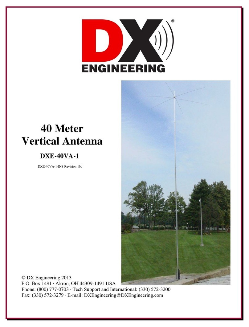
DX Engineering DXE-40VA-1 manual

DX Engineering

DX Engineering DXE-40VA-1 manual

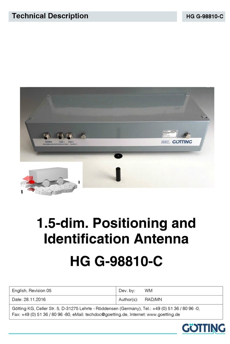
Gotting HG G-98810-C Technical description

Gotting

Gotting HG G-98810-C Technical description

RCA ANT500 Specifications

RCA

RCA ANT500 Specifications

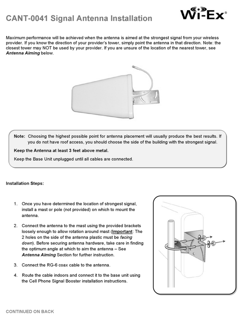
Wi-Ex CANT-0041 Installation

Wi-Ex

Wi-Ex CANT-0041 Installation

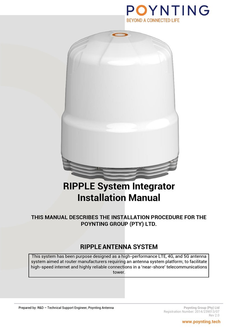
Poynting RIPPLE installation manual

Poynting

Poynting RIPPLE installation manual

Skywalker FMSS user guide

Skywalker

Skywalker FMSS user guide

Mti WIRELESS EDGE MT-386004/N installation instructions

Mti WIRELESS EDGE

Mti WIRELESS EDGE MT-386004/N installation instructions

ADC Digivance Installation and operation manual

ADC

ADC Digivance Installation and operation manual

Winegard AIR 360+ Operation guide

Winegard

Winegard AIR 360+ Operation guide

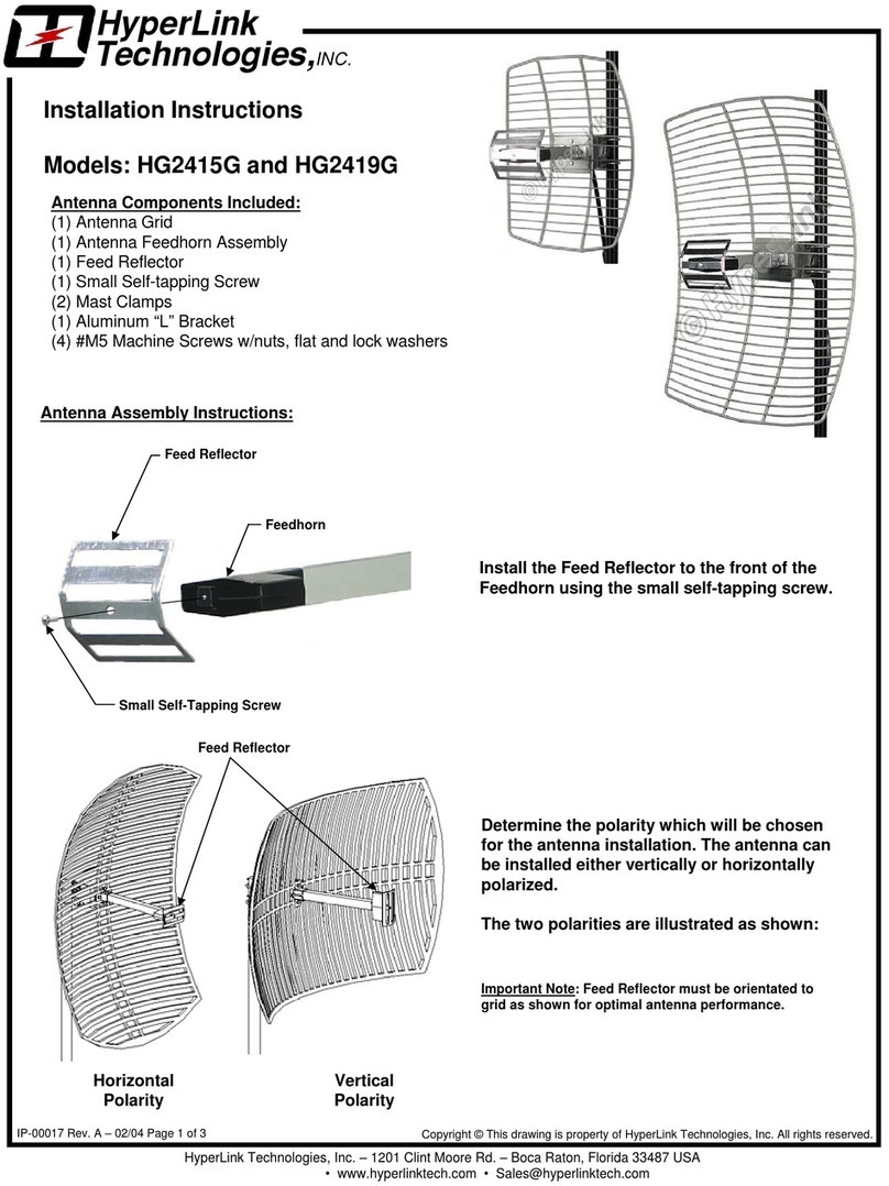
HyperLink Technologies HG2415G installation instructions

HyperLink Technologies

HyperLink Technologies HG2415G installation instructions

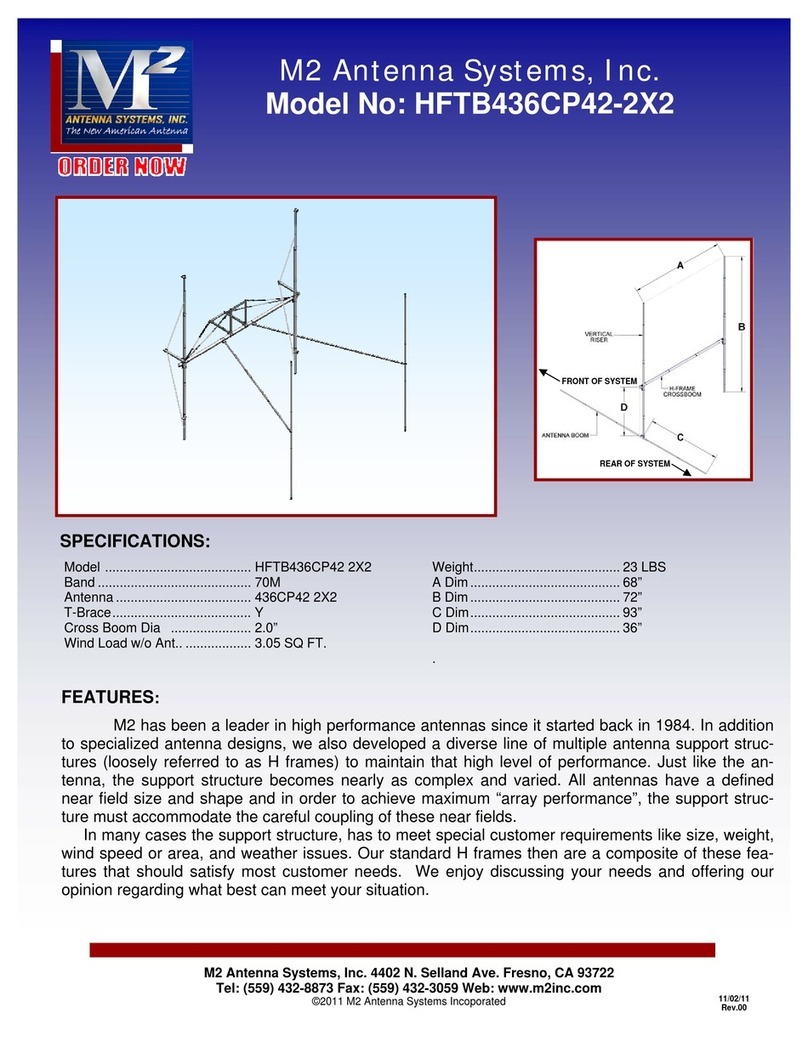
M2 HFTB436CP42-2X2 Assembly manual

M2

M2 HFTB436CP42-2X2 Assembly manual

Megasat Seaman 37 User manual and installation instructions

Megasat

Megasat Seaman 37 User manual and installation instructions

M2 Antenna Systems 7-10-30LP8 Assembly instructions

M2 Antenna Systems

M2 Antenna Systems 7-10-30LP8 Assembly instructions

LAPLACE INSTRUMENTS RF300 user guide

LAPLACE INSTRUMENTS

LAPLACE INSTRUMENTS RF300 user guide

manuals.online logo
manuals.online logoBrands
  • About & Mission
  • Contact us
  • Privacy Policy
  • Terms and Conditions

Copyright 2025 Manuals.Online. All Rights Reserved.