Codan 3040 System manual

HF RADIO COMMUNICATIONS
Installation Handbook
3040 Automatic Whip Antenna

No part of this handbook may be reproduced, transcribed,
translated into any language or transmitted in any form
whatsoever without the prior written consent of Codan
Limited.
© Copyright 2010 Codan Limited.
Codan part number 15-04166-EN Issue 1, June 2010.
Brand, product, and company names mentioned in this
document are trademarks or registered trademarks of their
respective holders.
The English version takes precedence over any translated
versions.

Automatic Whip Antenna 3040 Installation Handbook i
Table of contents
Introduction
1Overview
General . . . . . . . . . . . . . . . . . . . . . . . . . . . . . . . . . . . . . . . . . . . . . . . . . . . . . 4
Care and safety instructions . . . . . . . . . . . . . . . . . . . . . . . . . . . . . . . . . . . . . 5
Connectors . . . . . . . . . . . . . . . . . . . . . . . . . . . . . . . . . . . . . . . . . . . . . . . . . . 6
2 Installing the antenna
Disclaimer. . . . . . . . . . . . . . . . . . . . . . . . . . . . . . . . . . . . . . . . . . . . . . . . . . 10
What you need to consider . . . . . . . . . . . . . . . . . . . . . . . . . . . . . . . . . . . . . 10
Installing a 3040 Automatic Whip Antenna . . . . . . . . . . . . . . . . . . . . . . . . 18
Installing an NVIS kit with a 3040 Automatic Whip Antenna. . . . . . . . . . 21
3 Specifications
General . . . . . . . . . . . . . . . . . . . . . . . . . . . . . . . . . . . . . . . . . . . . . . . . . 23
Mechanical . . . . . . . . . . . . . . . . . . . . . . . . . . . . . . . . . . . . . . . . . . . . . . 24
Environmental . . . . . . . . . . . . . . . . . . . . . . . . . . . . . . . . . . . . . . . . . . . . 25
4 Accessories
Appendix A—Compliance
Introduction. . . . . . . . . . . . . . . . . . . . . . . . . . . . . . . . . . . . . . . . . . . . . . . . . 30
European R&TTE Directive . . . . . . . . . . . . . . . . . . . . . . . . . . . . . . . . . . . . 30
EMC and safety notices . . . . . . . . . . . . . . . . . . . . . . . . . . . . . . . . . . . . . . . 31
FCC compliance . . . . . . . . . . . . . . . . . . . . . . . . . . . . . . . . . . . . . . . . . . . . . 33
Register of hazardous substances . . . . . . . . . . . . . . . . . . . . . . . . . . . . . . . . 34

Table of contents
ii Automatic Whip Antenna 3040 Installation Handbook
Appendix B—Definitions
Standards and icons . . . . . . . . . . . . . . . . . . . . . . . . . . . . . . . . . . . . . . . . . . . 37
Acronyms and abbreviations . . . . . . . . . . . . . . . . . . . . . . . . . . . . . . . . . . . . 38
Units. . . . . . . . . . . . . . . . . . . . . . . . . . . . . . . . . . . . . . . . . . . . . . . . . . . . . . . 39
Unit multipliers . . . . . . . . . . . . . . . . . . . . . . . . . . . . . . . . . . . . . . . . . . . . . . 40
About this issue . . . . . . . . . . . . . . . . . . . . . . . . . . . . . . . . . . . . . . . . . . . . . . 40
Index
List of figures
Figure 1: 3040 Automatic Whip Antenna. . . . . . . . . . . . . . . . . . . . . 4
Figure 2: Connectors on the antenna tuner . . . . . . . . . . . . . . . . . . . . 6
Figure 3: Front view of the antenna control connector. . . . . . . . . . . 7
Figure 4: Mounting footprint . . . . . . . . . . . . . . . . . . . . . . . . . . . . . 12
Figure 5: Rear-mount location on sedan vehicle . . . . . . . . . . . . . . 13
Figure 6: Rear-mount location on off-road vehicle . . . . . . . . . . . . 14
Figure 7: Front-mount location on off-road vehicle . . . . . . . . . . . . 14
Figure 8: 3040 antenna with NVIS kit . . . . . . . . . . . . . . . . . . . . . . 21
List of tables
Table 1: Pinouts for the antenna control connector. . . . . . . . . . . . . 7
Table 2: 3040 to NGT connections . . . . . . . . . . . . . . . . . . . . . . . . 19
Table 3: General specifications . . . . . . . . . . . . . . . . . . . . . . . . . . . 23
Table 4: Mechanical specifications . . . . . . . . . . . . . . . . . . . . . . . . 24
Table 5: Environmental specifications . . . . . . . . . . . . . . . . . . . . . 25
Table 6: Accessories for the 3040 Automatic Whip
Antenna . . . . . . . . . . . . . . . . . . . . . . . . . . . . . . . . . . . . . . 27
Table 7: 有毒有害物质列表 (Register of hazardous
substances). . . . . . . . . . . . . . . . . . . . . . . . . . . . . . . . . . . . 34

Automatic Whip Antenna 3040 Installation Handbook 1
Introduction
This handbook is for installers of the 3040 Automatic Whip
Antenna. It assumes that you have experience in installing
antennas.
This handbook contains the following sections:
Section 1 Overview—provides an overview of the
antenna, connectors, and general information
Section 2 Installing the antenna—provides guidance on
how to position, install, and earth the antenna
Section 3 Specifications—provides the common
operational, environmental, and physical
specifications of the antenna
Section 4 Accessories—lists the accessories available for
the antenna
Appendix A Compliance—provides compliance information
and safety notices for your antenna
Appendix B Definitions—explains the terms and
abbreviations used in this handbook
There is an index at the end of this handbook.

Introduction
2 Automatic Whip Antenna 3040 Installation Handbook
This page has been left blank intentionally.

Overview
4 Automatic Whip Antenna 3040 Installation Handbook
General
The 3040 Automatic Whip Antenna is designed to provide
continuous tuning for vehicle-mounted transceivers that scan
multiple frequencies. It is designed to withstand extreme
environmental and physical conditions. When tuning, the
antenna seeks the optimum tuning point, ensuring that the best
communications possible are achieved.
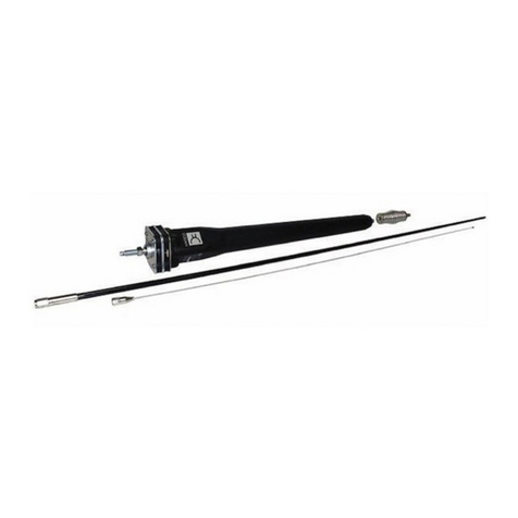
The 3040 Automatic Whip Antenna comprises:
• a 1.6 m (62 in) fibreglass or stainless steel whip
• an 865 mm (34.0 in) riser
•aspring
• an antenna tuner with connectors, base plate and earth
wire
Figure 1: 3040 Automatic Whip Antenna
base plate
antenna tuner spring
riser
whip
(fibreglass or
stainless steel)
240 mm
(9.4 in)
865 mm
(34.0 in)
1575 mm
(62.0 in)
115 mm
(4.5 in)
2795 mm
(3 yd)

Overview
Automatic Whip Antenna 3040 Installation Handbook 5
Care and safety instructions
You should unscrew the whip and riser from the antenna base
when the antenna is not in use.
When travelling in scrub or undergrowth, avoid overhanging
branches.

Overview
Automatic Whip Antenna 3040 Installation Handbook 7
Figure 3: Front view of the antenna control connector
Table 1: Pinouts for the antenna control connector
Pin no. Description
A+12VDC
BEarth
CTune
D Scan
E Tune status indicator
F Not used
A
B
C
D
E
F

Overview
8 Automatic Whip Antenna 3040 Installation Handbook
This page has been left blank intentionally.

Installing the antenna
10 Automatic Whip Antenna 3040 Installation Handbook
Disclaimer
What you need to consider
The antenna is a critical element in an HF communications
system. Correct installation of the antenna provides efficient
operation over the frequency range of the transceiver. A good
installation ensures the antenna provides optimum output
power during transmission and clear reception of weak
signals.
When installing the antenna you must consider:
• the location and mounting of the antenna
• how to provide a good earth plane for the antenna
• the routing of the coaxial and control cable
WARNING
The antenna should be installed by a suitably-
qualified technician, to the relevant standards
and approvals.
WARNING
While the following instructions are intended to
assist with installation, it is the purchaser’s
responsibility to ensure that the antenna is
installed with due regard to pedestrian and
vehicle-occupant safety, particularly in the
event of a vehicle accident. Codan accepts no
responsibility or liability in the event of injury
to pedestrians or vehicle occupants or any other
damage due to insecure or otherwise unsafe or
inappropriate installation of the antenna.

Installing the antenna
Automatic Whip Antenna 3040 Installation Handbook 11
Location
To obtain optimal radiation efficiency from your antenna, and
optimal reception at your antenna, it must be mounted in a
location that:
• is clear of surrounding body work
• supports a good earth plane
• supports the RF earthing required for correct tuning and
loading
• allows for best radiation (open and clear of all metal
obstructions)
When mounted, the antenna:
• must not obscure the driver’s vision
• must not obscure number plates or vehicle lights
• should not interfere with engine or car openings
• must clear electric power lines, overhanging trees,
bridges etc
• must not breach vehicle-licensing regulations
A mounted antenna must have:
• a strong anchorage for the base of the antenna
• a sound electrical connection to the vehicle chassis
The mounting footprint in Figure 4 on page 12 shows the
required space for the base of the antenna tuner.

Installing the antenna
12 Automatic Whip Antenna 3040 Installation Handbook
Figure 4: Mounting footprint
15 mm
96 mm
164 mm
96 mm
140 mm
NOTE
Allow 70 mm over the
cable connections and for
minimum bending radius
Connectors
70 mm

Installing the antenna
Automatic Whip Antenna 3040 Installation Handbook 13
Possible mounting locations that provide good electrical
performance of the 3040 Automatic Whip Antenna are shown
in the following photographs.
Figure 5: Rear-mount location on sedan vehicle

Installing the antenna
14 Automatic Whip Antenna 3040 Installation Handbook
Figure 6: Rear-mount location on off-road vehicle
Figure 7: Front-mount location on off-road vehicle
fibreglass canopy
left-hand drive
position
right-hand drive
position

Installing the antenna
Automatic Whip Antenna 3040 Installation Handbook 15
Mounting bracket
The antenna must be mounted on a sturdy metal plate (at least
8 mm (0.3 in) thick). The mounting bracket and fixing should
be able to withstand any vibrations induced from the vehicle
travelling over an off-road surface. A strong metal plate that is
large enough to support the antenna will also provide efficient
earthing. The plate must have a 15 mm (0.6 in) hole to accept
the mounting screw.
The bracket should be located so that any flexing of the
antenna assembly does not damage the panels of the vehicle.
The installed antenna should enable easy access to the
connectors.
CAUTION
If the antenna is front-mounted, it should be
mounted on the side opposite to the driving
position.
NOTE You should consider any overall height
restrictions that are relevant to your vehicle.

Installing the antenna
16 Automatic Whip Antenna 3040 Installation Handbook
Earthing
Most mobile antennas are considerably shorter than a quarter
wavelength at HF, and can exhibit an extremely low radiation
resistance. Consequently, their efficiency is reduced compared
with the quarter-wave radiator that they represent. This can be
improved by good installation practices, and most importantly,
by the provision of a low-impedance earth return for the
antenna.
Due to the relatively poor earth plane surrounding a mobile
HF antenna, best use should be made of what is available. A
reduction in any losses can increase antenna current and
radiation. This can often be achieved by providing a good
earth connection from the base of the antenna to nearby
bodywork. An earth wire is provided for this. Connections to
the vehicle chassis are not as effective because many 4WD
vehicles have insulating mountings from body to chassis.
A strong metal plate that is large enough to support the
antenna will provide efficient earthing. The plate should be
welded to the chassis or some other part of the vehicle’s frame.
The mounting bracket and plate must be free of rust and paint
to allow metal-to-metal contact between the base of the
antenna and the mounting bracket. This electrical bond is the
basis for effective RF earthing. RF currents flow on the
conductor surface, therefore good RF earthing requires
conductors with large surface areas.
The RF earth differs from the DC earth required by the battery
and the vehicle’s electrics. For more information on power
supply factors and earthing the transceiver, see the
documentation provided with the transceiver.
NOTE Conductive grease should be used on the
touching surfaces to help prevent corrosion.
Table of contents
Other Codan Antenna manuals
Popular Antenna manuals by other brands

AMX
AMX NXA-WAP2403A Specifications

Shakespeare Electronic
Shakespeare Electronic Galaxy Style 5225-XT-AIS installation instructions

Lectrosonics
Lectrosonics ALP690 instruction manual

COBHAM
COBHAM SAILOR 900 installation manual

Somogyi Elektronic
Somogyi Elektronic home FZ3 instruction manual

Sony
Sony AN-820A operating instructions