Black Max BM25CSAC User manual
OPERATOR’S MANUAL
MANUAL DEL OPERADOR
25cc 2-CYCLE
STRING TRIMMERS
RECORTADORAS DE HILO
DE DOS TIMPOS 25 cc
BM25CSAC/BM25CSACVNM
BM25SSAC/BM25SSACVNM
To register your Black Max product,
please visit:
www.blackmaxtools.com
Para registrar su producto de Black
Max, por favor visita:
www.blackmaxtools.com
SAVE THIS MANUAL
FOR FUTURE REFERENCE GUARDE ESTE MANUAL
PARA FUTURAS CONSULTAS
WARNING: To reduce the risk of injury, the user
must read and understand the operator’s manual before
using this product.
TABLE OF CONTENTS
General Safety Rules ............................................................2-3
Specific Safety Rules...............................................................3
Symbols ...................................................................................4
Features ...................................................................................5
Assembly ..............................................................................5-6
Operation ..............................................................................7-9
Maintenance .......................................................................9-12
Troubleshooting.....................................................................13
Parts Ordering/Service............................................. Back Page
ADVERTENCIA: Para reducir el riesgo de
lesiones, el usuario debe leer y comprender el manual
del operador antes de usar este producto.
ÍNDICE DE CONTENIDO
Reglas de seguridad generales ............................................2-3
Reglas de seguridad específicas.............................................3
Símbolos ..................................................................................4
Características .........................................................................5
Armado .................................................................................5-6
Funcionamiento ....................................................................7-9
Mantenimiento ..................................................................10-13
Solución de problemas.....................................................14-15
Pedidos de piezas/servicio................................. Pág. posterior
BM25CSAC/
BM25CSACVNM
BM25SSAC/
BM25SSACVNM
ii
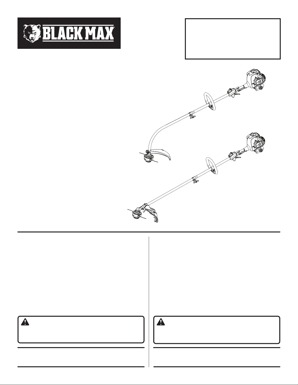
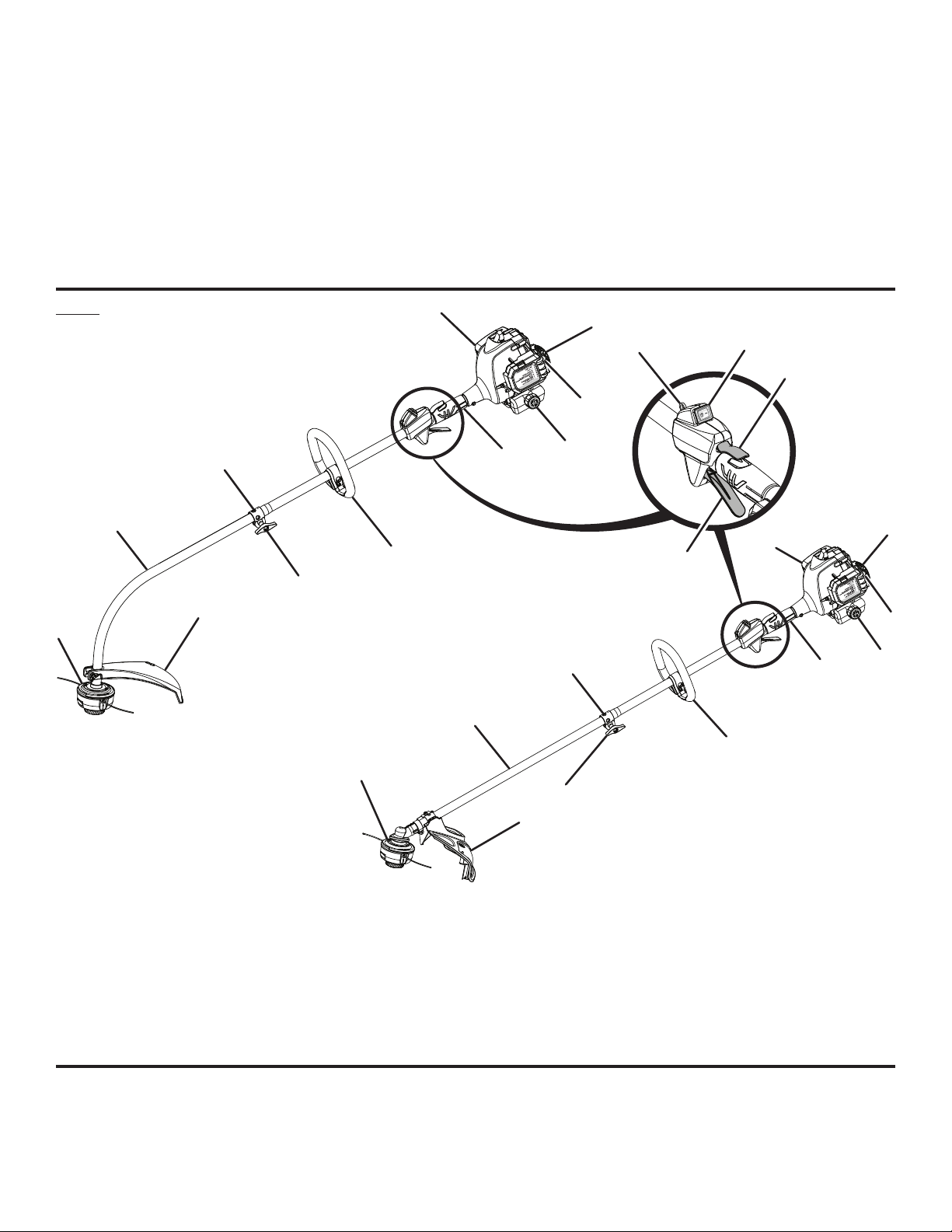
Fig. 1
A - Bump feed string head (cabezal del hilo con
alimentación por golpe)
B - Drive shaft housing (alojamiento del eje de
impulsión)
C - Coupler (acoplador)
D - Front handle (mango delantero)
E - Strap hanger (colgador para la correa)
F - Stop switch (interruptor de parada)
L
F
G
BM25CSAC/
BM25CSACVNM
A
B
N
M
C
D
I
H
J
K
P
J
K
P
BM25SSAC/
BM25SSACVNM
H
M
O
A
B
C
D
I
G - Trigger lock-out (seguro del gatillo)
H - Starter grip and rope (mango del arrancador
y cuerda)
I - Primer bulb (bomba de cebado)
J - Fuel cap (tapa del tanque)
K - Rear handle (mango trasero)
L - Throttle trigger (gatillo del acelerador)
M
- Knob (perilla)
N - Curved shaft grass deflector (deflector de
pasto del eje curvo)
O - Straight shaft grass deflector (deflector de
pasto para eje recto)
P - Muffler (silenciador)
See this fold-out section for all the figures
referenced in the operator’s manual.
Vea esta sección de la página desplegable para
todas las figuras mencionó en el manual del operador.
E

iii
Fig. 2
A - Button (botón)
B - Guide recess (hueco guía)
C - Coupler (acoplador)
D - Power head shaft (eje del cabezal motor)
E - Knob (perilla)
F - Positioninghole(orificiodeposicionamiento)
G - Trimmer attachment (aditamento para
recortar)
AB
CD
E
F
G
A - Bolt (perno)
B - Front handle (mango delantero)
C - Wing nut (tuerca de mariposa)
A
B
C
Fig. 5
A - Straight shaft grass deflector (deflector de
pasto para eje recto)
B - Slot (ranura)
C - Tab (orejeta)
D - Bolt (perno)
A
BC
D
D
A - Stop switch (interruptor de parada)
B - Trigger lock-out (seguro del gatillo)
C - Throttle trigger (gatillo del acelerador)
D - Starter grip and rope (mango del arrancador
y cuerda)
Fig. 6
A
B
C
Fig. 4
A - Bolt (perno)
B - Bracket (placa)
C - Wing nut (tuerca de mariposa)
D - Curved shaft grass deflector (deflector de
pasto del eje curvo)
A
B
C
D
A - Stop switch (interruptor de parada)
B - Trigger lock-out (seguro del gatillo)
C - Primer bulb (bomba de cebado)
D - Throttle trigger (gatillo del acelerador)
Fig. 7 A
B
C
D
Fig. 8
A - Choke lever in FULL CHOKE position
[palanca del anegador en posición de FULL
CHOKE (anegación máxima)]
B - Choke lever in HALF CHOKE position
(palanca del anegador en posición de HALF
CHOKE (anegación media)]
C - Choke lever in RUN position [palanca del
anegador en posición de RUN (marcha)]
A
B
C
Fig. 3

iv
A - String head housing (alojamiento del cabezal
de hilo)
B - Depress tabs (presione los orejetas)
PROPER OPERATING POSITION
POSICIÓN CORRECTA PARA EL MANEJO
DE LA HERRAMIENTA
Fig. 9
A - Curved shaft trimmer (recortadora de eje
curvo)
B - Dangerous cutting area (área peligrosa de
corte)
C - Direction of rotation (sentido de rotación)
D - Best cutting area (mejor área de corte)
Fig. 10 A
B
C
D
A - Eyelet (ojillo)
B - Arrows (flechas)
C - Pull strings (tira del hilo)
D - Rotate the bump knob (gire a la derecha el
perilla percusiva)
Fig. 13
B
A - Straight shaft trimmer (recortadora de eje
recto)
B - Dangerous cutting area (área peligrosa de
corte)
C - Best cutting area (mejor área de corte)
D - Direction of rotation (sentido de rotación)
Fig. 11
B
A
C
D
A - Straight shaft trimmer cut-off blade (cuchilla
de corte de hilo de la recortadora de eje
recto)
B - Curved shaft trimmer cut-off blade (cuchilla
de corte de hilo de la recortadora de eje
recto)
Fig. 12
B
A
A
D
C
Fig. 14
B
B
A
v
Fig. 18
B
D
A - Latch (pestillo)
B - Air filter (filtro de aire)
C - Air filter cover (tapa del filtro de aire)
D - Slots (ranuras)
E - Tabs (lengüetas)
A
E
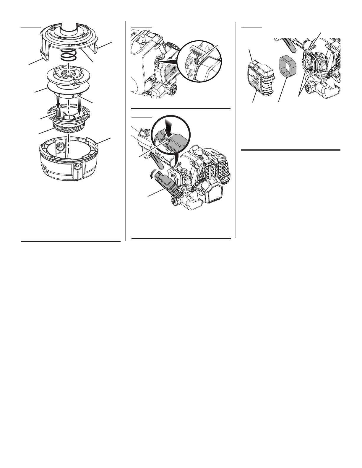
Fig. 16
A - Idle speed screw (tornillo de marcha lenta)
A
Fig. 17
A
B
A - Latch (pestillo)
B - Air filter cover (tapa del filtro de aire)
Fig. 15
A - Upper string head housing (alojamiento del
cabezal de hilo superior)
B - Tabs (lengüetas)
C - Lower string head housing (alojamiento del
cabezal de hilo inferior)
D - Spool (carrete)
E - Bump knob (perilla percusiva)
F - Spool slots (ranuras de carrete)
G - Knob ribs (costillas de la perilla)
BA
D
F
G
EC
BC

Page 2 — English
WARNING:
READ AND UNDERSTAND ALL INSTRUCTIONS.
Failure to follow all instructions listed below may result in
electric shock, fire and/or serious personal injury.
READ ALL INSTRUCTIONS
For safe operation, read and understand all instructions
before using this product. Follow all safety instructions.
Failure to follow all safety instructions listed below, can
result in serious personal injury.
Do not allow children or untrained individuals to use this
unit.
Do not start or operate the engine in a confined space,
building, near open windows, or in other unventilated
space where dangerous carbon monoxide fumes can
collect. Carbon monoxide, a colorless, odorless, and
extremely dangerous gas, can cause unconsciousness
or death.
Clear the work area before each use. Remove all objects
such as rocks, broken glass, nails, wire, or loose string
which can be thrown or become entangled in the cutting
line or blade.
Always wear eye protection with side shields marked to
comply with ANSI Z87.1 along with hearing protection
when operating this equipment. Failure to do so could
result in objects being thrown into your eyes and other
possible serious injuries.
Wear heavy, long pants, long sleeves, boots, and gloves.
Do not wear loose fitting clothing, short pants, sandals,
or go barefoot. Do not wear jewelry of any kind.
Heavy protective clothing may increase operator fatigue,
which could lead to heat stroke. During weather that is
hot and humid, heavy work should be scheduled for early
morning or late afternoon hours when temperatures are
cooler.
Never operate this unit on the operator’s left side.
Secure long hair above shoulder level to prevent entangle-
ment in moving parts.
Keep all bystanders, children, and pets at least
50 ft. away. Bystanders should be encouraged to wear
eye protection. If you are approached, stop the engine
and cutting attachment. In the case of bladed units, there
is the added risk of injury to bystanders from being struck
with the moving blade in the event of a blade thrust or
other unexpected reaction of the saw.
Do not operate this unit when you are tired, ill, upset, or
under the influence of alcohol, drugs, or medication.
Do not operate in poor lighting.
Keep firm footing and balance. Do not overreach. Over-
reaching can result in loss of balance or exposure to hot
surfaces.
Do not use on a ladder or unstable support. Stable foot-
ing on a solid surface enables better control of the unit
in unexpected situations.
Keep all parts of your body away from any moving part.
To avoid hot surfaces, never operate the unit with the
bottom of the engine above waist level.
Do not touch area around the muffler or cylinder of the
unit, these parts get hot from operation. Contact with hot
surfaces could result in possible serious personal injury.
Always stop the engine and remove the spark plug wire
before making any adjustments or repairs except for
carburetor adjustments.
Inspect the unit before each use for loose fasteners, fuel
leaks, etc. Replace any damaged parts before use.
Never use blades, flailing devices, wire, or rope on trim-
mer attachment. Never use flailing devices, wire, or rope
on any attachment.
The cutting attachment should never rotate at idle during
normal use. The cutting attachment may rotate at idle
during carburetor adjustments.
It has been reported that vibrations from hand-held tools
may contribute to a condition called Raynaud’s Syndrome
in certain individuals. Symptoms may include tingling,
numbness, and blanching of the fingers, usually apparent
upon exposure to cold. Hereditary factors, exposure to
cold and dampness, diet, smoking, and work practices
are all thought to contribute to the development of these
symptoms. It is presently unknown what, if any, vibrations
or extent of exposure may contribute to the condition.
There are measures that can be taken by the operator to
possibly reduce the effects of vibration:
a) Keep your body warm in cold weather. When operating
the unit wear gloves to keep hands and wrists warm.
It is reported that cold weather is a major factor con-
tributing to Raynaud’s Syndrome.
b) After each period of operation, exercise to increase
blood circulation.
c) Take frequent work breaks. Limit the amount of
exposure per day.
d) Keep the tool well maintained, fasteners tightened,
and worn parts replaced.
If you experience any of the symptoms of this condition,
immediately discontinue use and see your physician
about these symptoms.
Mix and store fuel in a container approved for gasoline.
Mix fuel outdoors where there are no sparks or flames.
Wipe up any fuel spillage. Move 30 ft. away from refueling
site before starting engine. Slowly remove the fuel cap
after stopping engine. Do not smoke when refueling.
Stop the engine and allow to cool before refueling or
storing the unit.
GENERAL SAFETY RULES

Page 3 — English
Inspect before use. Replace damaged parts. Make sure
fasteners are in place and secure. Check for fuel leaks.
Replace string head if cracked, chipped, or damaged
in any way. Be sure the string head or blade is properly
installed and securely fastened. Failure to do so can cause
serious injury.
Make sure all guards, straps, deflectors, and handles are
properly and securely attached.
Use only recommended or equivalent replacement line in
the cutting head. Do not use any other cutting attachment.
To install any other type of replacement line or cutting
head to this string trimmer can result in serious personal
injury. Never use, for example, wire or wire-rope, which
can break off and become a dangerous projectile.
Never operate unit without the grass deflector in place
and in good condition.
Maintain a firm grip on both handles while trimming. Keep
string head below waist level. Never cut with the string
head located over 30 in. or more above the ground.
This product is intended for infrequent use by homeown-
ers and other occasional users for such general applica-
tions as trimming light and heavy vegetation, etc. It is not
intended for prolonged use. Prolonged periods of opera-
tion can cause circulatory problems in the user’s hands
due to vibration. For such use, it may be appropriate to
use a product having an anti-vibration feature.
Save these instructions. Refer to them frequently and use
them to instruct others who may use this tool. If you loan
someone this tool, loan them these instructions also.
Allow the engine to cool; empty the fuel tank and secure
the unit from moving before transporting in a vehicle.
Wear your protective equipment and observe all safety
instructions. For units equipped with a clutch, be sure
the cutting attachment stops turning when the engine
idles. When the unit is turned off make sure the cutting
attachment has stopped before the unit is set down.
We recommend taking your equipment to a qualified
service center for repair, as service performed by in-
experienced or unqualified persons may damage the
equipment, create unsafe conditions, injury to user and/
or void your warranty.
GENERAL SAFETY RULES
SPECIFIC SAFETY RULES

Page 4 — English
SYMBOLS
Some of the following symbols may be used on this product. Please study them and learn their meaning for safe
operation of this product.
SYMBOL NAME EXPLANATION
Safety Alert Indicates a potential personal injury hazard.
Read Operator’s Manual To reduce the risk of injury, user must read and under-
stand operator’s manual before using this product.
Eye and Hearing Protection
Always wear eye protection with side shields marked to
comply with ANSI Z87.1 along with hearing protection
when operating this equipment.
Wear Gloves Wear non-slip, heavy-duty protective gloves when
handling this equipment.
Wear Safety Footwear Wear non-slip safety footwear when using this
equipment.
Keep Bystanders Away Keep all bystanders at least 50 ft. away.
Ricochet Thrown objects can ricochet and result in personal injury
or property damage.
No Blade Do not install or use any type of blade on a product dis-
playing this symbol.
Hot Surface To reduce the risk of injury or damage, avoid contact
with any hot surface.
Gasoline and Lubricant
Use unleaded gasoline intended for motor vehicle use
with an octane rating of 87 [(R + M) / 2] or higher. This
product is powered by a 2-cycle engine and requires
pre-mixing gasoline and 2-cycle lubricant.
The following signal words and meanings are intended to explain the levels of risk associated with this product.
SYMBOL SIGNAL MEANING
DANGER: Indicates a hazardous situation, which, if not avoided, will result in death or
serious injury.
WARNING: Indicates a hazardous situation, which, if not avoided, could result in death or
serious injury.
CAUTION: Indicates a hazardous situation, that, if not avoided, may result in minor or
moderate injury.
NOTICE: (Without Safety Alert Symbol) Indicates information considered important, but
not related to a potential injury (e.g. messages relating to property damage).

Page 5 — English
PACKING LIST
Curved Shaft
Trimmer Assembly
Front Handle with Hardware
Curved Shaft Grass Deflector
Bottle of 2-Cycle Lubricant
Operator’s Manual
Straight Shaft
Trimmer Assembly
Front Handle with Hardware
Straight Shaft Grass Deflector
Bottle of 2-Cycle Lubricant
Operator’s Manual
WARNING:
If any parts are damaged or missing do not operate this
product until the parts are replaced. Use of this product
with damaged or missing parts could result in serious
personal injury.
UNPACKING
This product requires assembly.
Carefully remove the items from the box. Make sure that
all items listed in the Packing List are included.
WARNING:
Do not use this product if any parts in the Packing List
are already assembled to your product when you unpack
it. Parts on this list are not assembled to the product by
the manufacturer and require customer installation. Use
of a product that may have been improperly assembled
could result in serious personal injury.
Inspect the unit carefully to make sure no damage oc-
curred during shipping.
Do not discard the packing material until you have
carefully inspected and satisfactorily operated the
product.
If any parts are damaged or missing, please call
1-800-726-5760 for assistance.
FEATURES
ASSEMBLY
PRODUCT SPECIFICATIONS
Line cutting width
Curved Shaft............................................................................................................................................................17 in.
Straight Shaft...........................................................................................................................................................18 in.
Engine displacement ......................................................................................................................................................25cc
Line diameter.............................................................................................................................................................0.095 in.
KNOW YOUR PRODUCT
See Figure 1.
The safe use of this product requires an understanding of
the information on the tool and in this operator’s manual as
well as a knowledge of the project you are attempting. Before
use of this product, familiarize yourself with all operating
features and safety rules.
BUMP FEED STRING HEAD
The bump feed string head allows easy line advance during
trimmer operation.
ERGONOMIC DESIGN
The design of the trimmer provides for easy handling. It is
designed for comfort and ease of grasp when operating in
different positions and at different angles.
GRASS DEFLECTOR
The product includes a grass deflector that helps protect
you from flying debris.
TOP-MOUNTED ENGINE
The top-mounted engine improves balance and is located
away from the dust and debris of the cutting area.

Page 6 — English
WARNING:
Do not attempt to modify this product or create acces-
sories not recommended for use with this product. Any
such alteration or modification is misuse and could result
in a hazardous condition leading to possible serious
personal injury.
WARNING:
To prevent accidental starting that could cause serious
personal injury, always disconnect the engine spark plug
wire from the spark plug when assembling parts.
INSTALLING THE POWER HEAD TO THE
ATTACHMENT
See Figure 2.
WARNING:
Never install, remove, or adjust any attachment while
power head is running. Failure to stop the engine can
cause serious personal injury.
The attachment connects to the power head by means of
a coupler device.
Stop the engine and disconnect the spark plug wire.
Loosen the knob on the coupler of the power head shaft.
Push in the button located on the trimmer attachment.
Align the button with the guide recess on the power head
coupler and slide the two shafts together. Rotate the trim-
mer attachment until the button locks into the positioning
hole.
NOTE: If the button does not release completely in the
positioning hole, the shafts are not locked into place.
Slightly rotate from side to side until the button is locked
into place.
Tighten the knob securely.
WARNING:
Be certain the knob is fully tightened before operating
equipment; check it periodically for tightness during use
to avoid serious personal injury.
REMOVING THE ATTACHMENT FROM THE
POWER HEAD
Stop the engine and disconnect the spark plug wire.
Loosen the knob.
Push in the button and twist the shafts to remove and
separate ends.
ATTACHING THE FRONT HANDLE
See Figure 3.
Remove wing nut and bolt from the front handle.
Install the front handle onto the top side of the power
head shaft in the area indicated by the label.
Place the bolt through the front handle.
NOTE: The hex bolt head fits inside the hex recess
molded into one side of the handle.
Reinstall the wing nut.
Tighten wing nut securely.
ATTACHING THE GRASS DEFLECTOR
WARNING:
The line cutting blade on the grass deflector is sharp.
Avoid contact with the blade. Failure to avoid contact
can result in serious personal injury.
TO ATTACH THE CURVED SHAFT GRASS
DEFLECTOR
See Figure 4.
Remove bolt and wing nut from grass deflector.
Press the grass deflector onto the bottom of the curved
shaft as shown.
Insert the bolt through the grass deflector and the bracket
on the curved shaft.
Place the wing nut on the bolt and tighten securely.
TO ATTACH THE STRAIGHT SHAFT GRASS
DEFLECTOR
See Figure 5.
Remove the bolt from the grass deflector.
Insert the tab on the mounting bracket in the slot on the
grass deflector.
Align the screw hole in the mounting bracket with the
screw hole in the grass deflector.
Insert the bolt through the mounting bracket and into the
grass deflector.
Tighten the bolt securely.
ASSEMBLY

Page 7 — English
WARNING:
Do not allow familiarity with this product to make you
careless. Remember that a careless fraction of a second is
sufficient to inflict serious injury.
WARNING:
Always wear eye protection with side shields marked to
comply with ANSI Z87.1, along with hearing protection.
Failure to do so could result in objects being thrown into
your eyes and other possible serious injuries.
WARNING:
Never use blades, flailing devices, wire, or rope on this
product. Do not use any attachments or accessories not
recommended by the manufacturer of this product. The
use of attachments or accessories not recommended
can result in serious personal injury.
NOTICE:
The spark arrestor on this product has not been evalu-
ated by the USDA Forest Service and cannot be used on
U.S. forest lands. In addition, product users must comply
with Federal, State, and local fire prevention regulations.
Check with appropriate authorities. Contact customer
service or a qualified service center to purchase a re-
placement spark arrestor.
NOTICE:
Before each use, inspect the entire product for damaged,
missing, or loose parts such as screws, nuts, bolts, caps,
etc. Tighten securely all fasteners and caps and do not
operate this product until all missing or damaged parts are
replaced. Please contact customer service or a qualified
service center for assistance.
ETHANOL-BLENDED FUELS
NOTICE:
Do not use E15 or E85 fuel in this product. It is a viola-
tion of federal law and will damage the unit and void
your warranty. Only use unleaded gasoline containing
up to 10% ethanol.
NOTE: To improve performance when using oxygenated
fuels, we recommend the use of Ethanol Shield 2-cycle
lubricant.
FUELING AND REFUELING THE TRIMMER
WARNING:
Gasoline and its vapors are highly flammable and ex-
plosive. To prevent serious personal injury and property
damage, handle it with care. Keep away from ignition
sources and open flames, handle outdoors only, do not
smoke and wipe up spills immediately.
FUEL MIXTURE
This product is powered by a 2-cycle engine and requires
pre-mixing gasoline and 2-cycle lubricant. Pre-mix unleaded
gasoline and 2-cycle engine lubricant in a clean container
approved for gasoline. DO NOT mix quantities larger than
usable in a 30-day period.
Recommended fuel: This engine is certified to operate on
unleaded gasoline intended for automotive use.
NOTE: We recommend you use Ethanol Shield 2-cycle
lubricant or an equivalent high-quality synthetic 2-cycle
lubricant in this product. Mix at 2.6 oz. per gallon (US).
Do not use automotive lubricant or 2-cycle outboard
lubricant.
HIGH QUALITY 2-CYCLE ENGINE LUBRICANT
GASOLINE LUBRICANT
1.0 gal. (US) (3.8 liter) 2.6 oz. (76 ml)
2.5 gal. (US) (9.5 liter) 6.4 oz. (189 ml)
FILLING TANK
Clean surface around fuel cap to prevent contamination.
Loosen fuel cap slowly. Rest the cap on a clean surface.
Carefully pour fuel mixture into the tank. Avoid spillage.
Prior to replacing the fuel cap, clean and inspect the
gasket.
Immediately replace fuel cap and hand tighten. Wipe up
any fuel spillage.
NOTE: It is normal for smoke to be emitted from a new
engine after first use.
WARNING:
Always shut off engine before fueling. Never remove fuel
cap or add fuel to a machine with a running or hot engine.
Make sure the unit is sitting on a flat, level surface and
only add fuel outdoors. If the engine is hot, let the unit cool
for at least five minutes before adding fuel. After fueling,
immediately replace fuel cap and tighten securely. Move
at least 30 ft. from refueling site before starting engine. Do
not smoke and stay away from open flames and sparks!
Failure to follow these instructions could result in a fire
and cause serious personal injury.
OPERATION

Page 8 — English
STARTING AND STOPPING
See Figures 6 - 8.
Trimmer should be on a flat, bare surface for starting.
To start a cold engine:
Lay the product on a flat, bare surface.
Push the primer bulb approximately ten times.
Set the choke lever to FULL CHOKE.
Depress lock-out button and squeeze throttle trigger
fully and pull starter grip and rope sharply until engine
attempts to start (no more than 4x).
Set the choke lever to HALF CHOKE.
Pull starter grip and rope until engine runs, no more than
6 pulls.
Allow engine to run for 10 seconds, then set the choke
lever to RUN.
NOTE: In cooler environments, additional pulls of the
starter grip and rope may be required with the choke
lever in the FULL CHOKE position.
To start a warm engine:
Lay the product on a flat, bare surface.
Push the primer bulb up to ten times.
Set the choke lever to RUN.
Depress lock-out button and squeeze throttle trigger fully,
pull the starter cord.
NOTE: If the product does not start, repeat the previous
steps.
To stop the engine:
To stop the engine, depress the STOP switch to the stop
position “ ”.
IF ASSISTANCE IS REQUIRED FOR THIS PRODUCT:
Do not return this product to the retail store where it was
purchased. Please call our Customer Service Department
for any issues you may have.
For Help Call: 1-800-726-5760
OPERATING THE TRIMMER
See Figure 9.
WARNING:
Engine housing can become hot during trimmer opera-
tion. Do not rest or place your arm, hand, or any body
part against the engine housing during trimmer operation.
Only hold the trimmer as shown in figure 9 with all body
parts clear of engine housing. Extended contact with
the engine housing can result in burns or other injuries.
WARNING:
Always position the unit on the operator’s right side. The
use of the unit on the operator’s left side will expose the
user to hot surfaces and can result in possible burn injury.
WARNING:
To avoid burns from hot surfaces, never operate unit with
the bottom of the engine above waist level.
Hold the trimmer with your right hand on the rear handle
and your left hand on the front handle. Keep a firm grip with
both hands while in operation. Trimmer should be held at a
comfortable position with the rear handle about hip height.
Always operate trimmer in RUN position. Cut tall grass
from the top down. This will prevent grass from wrapping
around the shaft housing and string head which could cause
damage from overheating. If grass becomes wrapped around
the string head, STOP THE ENGINE, disconnect the spark
plug wire, and remove the grass. Prolonged cutting at partial
throttle will result in lubricant dripping from the muffler.
WARNING:
Always hold the string trimmer away from the body keep-
ing clearance between the body and the product. Any
contact with the housing or string trimmer cutting head
can result in burns and/or other serious personal injury.
CUTTING TIPS
See Figures 9 - 11.
Avoid hot surfaces by always keeping the tool away from
your body. (Proper operating position shown in figure 9.)
Keep the trimmer tilted toward the area being cut; this is
the best cutting area.
The curved shaft trimmer cuts when passing the unit from
right to left. The straight shaft trimmer cuts when passing
the unit from left to right. This will avoid throwing debris at
the operator. Avoid cutting in the dangerous area shown
in illustration.
Use the tip of line to do the cutting; do not force string
head into uncut grass.
Wire and picket fences cause extra line wear, even break-
age. Stone and brick walls, curbs, and wood may wear
line rapidly.
Avoid trees and shrubs. Tree bark, wood moldings, siding,
and fence posts can easily be damaged by the line.
OPERATION

Page 9 — English
TO ADVANCE THE CUTTING LINE
Line advance is controlled by tapping the string head on
grass while running engine at full throttle.
Run engine at full throttle.
Tap the knob on ground to advance line. The line ad-
vances each time the knob is tapped. Do not hold the
knob on the ground.
NOTE: The line trimming cut-off blade on the grass deflector
will cut the line to the correct length.
NOTE: If the line is worn too short you may not be able to
advance the line by tapping it on the ground. If so, stop the
engine and manually advance the line.
To advance the cutting line manually:
Stop the engine and disconnect the spark plug wire.
Push the knob in while pulling on line(s) to manually ad-
vance the line.
GRASS DEFLECTOR LINE TRIMMING CUT-
OFF BLADE
See Figure 12.
The trimmer is equipped with a line trimming cut-off blade
on the grass deflector. For best cutting, advance line until it
is trimmed to length by the cut-off blade. Advance the line
whenever you hear the engine running faster than normal,
or when trimming efficiency diminishes. This will maintain
best performance and keep the line long enough to advance
properly.
OPERATION
MAINTENANCE
Normal maintenance, replacement or repair of emission con-
trol devices and systems may be performed by any qualified
repair establishment or individual with original or equivalent
parts. Warranty and recall repairs must be performed by a
authorized service center; please contact customer service
for assistance.
WARNING:
Before inspecting, cleaning, or servicing the machine,
shut off engine, wait for all moving parts to stop, and
disconnect spark plug wire and move it away from spark
plug. Failure to follow these instructions can result in
serious personal injury or property damage.
WARNING:
Always wear eye protection with side shields marked to
comply with ANSI Z87.1, along with hearing protection.
Failure to do so could result in objects being thrown into
your eyes and other possible serious injuries.
WARNING:
When servicing, use only recommended or equivalent
replacement parts. Use of any other parts could create
a hazard or cause product damage.
NOTICE:
Periodically inspect the entire product for damaged,
missing, or loose parts such as screws, nuts, bolts, caps,
etc. Tighten securely all fasteners and caps and do not
operate this product until all missing or damaged parts are
replaced. Please contact customer service or a qualified
service center for assistance.
GENERAL MAINTENANCE
Avoid using solvents when cleaning plastic parts. Most
plastics are susceptible to damage from various types of
commercial solvents and may be damaged by their use.
Use clean cloths to remove dirt, dust, lubricant, grease, etc.
WARNING:
Do not at any time let brake fluids, gasoline, petroleum-
based products, penetrating lubricants, etc., come in con-
tact with plastic parts. Chemicals can damage, weaken or
destroy plastic which could result in serious personal
injury.
LINE REPLACEMENT
See Figure 13.
Use only .095 in. trimmer line. Use original manufacturer’s
replacement line for best performance.
Stop the engine and disconnect the spark plug wire.
Rotate the bump knob clockwise as necessary to align the
arrows on the bump knob with the arrows on the string
head housing.

Page 10 — English
Cut one piece of trimmer line 16 ft. long. Insert the line
into the eyelet on the string head housing. Push until the
end of the line comes out the other side of the housing.
Pull the line until equal amounts of line appear on both
sides of the housing.
NOTE: Line may jam if more than 16 ft. is loaded.
Rotate the bump knob clockwise to wind the line on the
spool until approximately 6 in. of line is showing on each
side.
Push the bump knob down while pulling on line(s) to
manually advance the line.
CLEARING LINE JAM AND/OR REPLACING
BUMP KNOB
See Figures 14 - 15.
Stop the engine and disconnect the spark plug wire.
Depress the tabs on the side of the string head housing
to remove the lower string head housing.
NOTE: The housing is spring loaded and will self eject
when the tabs are depressed. It is not necessary to re-
move the upper string head housing from the drive shaft.
Push the spool and bump knob through the string head
housing and remove the string from the spool.
If replacing the bump knob, remove the old knob from
the spool. Align the knob ribs with the spool slots and
place the new bump knob onto the spool. If you are not
replacing the bump knob, skip this step.
Insert the bump knob and spool assembly through the
opening in the string head housing.
Align the slots on the lower string head housing with the
tabs on the upper string head housing.
Push the housing together until the tabs snap into place.
NOTE: Hold the spool by the knob while completing the
installation.
Install line as described in Line replacement.
CLEANING THE EXHAUST PORT, MUFFLER,
AND SPARK ARRESTOR
NOTICE:
The spark arrestor on this product has not been evalu-
ated by the USDA Forest Service and cannot be used on
U.S. forest lands. In addition, product users must comply
with Federal, State, and local fire prevention regulations.
Check with appropriate authorities. Contact customer
service or a qualified service center to purchase a re-
placement spark arrestor.
NOTE: Depending on the type of fuel used, the type and
amount of lubricant used, and/or your operating conditions, the
exhaust port, muffler, and/or spark arrestor screen may
become blocked with carbon deposits. If you notice a
power loss with your gas powered tool, you may need to
remove these deposits to restore performance. We highly
recommend that only qualified service technicians perform
this service.
The spark arrestor must be cleaned or replaced every 50
hours or yearly to ensure proper performance of your prod-
uct. Spark arrestors may be in different locations depending
on the model purchased. Please contact your nearest service
dealer for the location of the spark arrestor for your model.
IDLE SPEED ADJUSTMENT
See Figure 16.
WARNING:
The cutting head will move when adjusting the idle speed.
Wear all protective clothing and keep all bystanders,
children, and pets at least 50 ft. away. Make adjustments
with the unit supported by hand so that the blade/cutting
head does not contact the ground or any object. Keep
all parts of your body away from the cutting head and
muffler. Failure to follow these instructions could result
in serious personal injury.
If the cutting attachment turns at idle, the idle speed screw
needs adjusting on the engine. Turn the idle speed screw
counterclockwise to reduce the idle RPM and stop the cut-
ting attachment movement. If the cutting attachment still
moves at idle speed, contact a service dealer for adjustment
and discontinue use until the repair is made.
WARNING:
The cutting attachment should never turn at idle. Turn
the idle speed screw counterclockwise to reduce the
idle RPM and stop the cutting attachment, or contact a
service dealer for adjustment and discontinue use until
the repair is made. Serious personal injury could result
from the cutting attachment turning at idle.
CLEANING THE AIR FILTER
See Figures 17 - 18.
For proper performance and long life, keep air filter clean.
Remove the air filter cover by pushing down on the latches
while gently pulling off the cover.
Remove the air filter.
Clean the foam filter element with warm soapy water.
Rinse and let dry.
NOTE: If the foam filter element is damaged, it should be
replaced.
Apply a light coat of engine oil to the foam filter element,
then squeeze it out.
Reinstall the air filter.
NOTE: Make sure the filter is seated properly inside the
cover. Installing the filter incorrectly will allow dirt to enter
the engine, causing rapid engine wear.
MAINTENANCE

Page 11 — English
Replace the air filter cover by placing the slots on the air
filter cover over the tabs on the housing, then push the
cover down until it snaps securely in place.
FUEL CAP, TANK, AND LINES
WARNING:
Check for fuel leaks. A leaking fuel cap, tank, or line is a
fire hazard and must be replaced immediately. If you find
any leaks, correct the problem before using the product.
Failure to do so could result in a fire that could cause
serious personal injury.
The fuel cap contains a non-serviceable filter and a check
valve. A clogged fuel filter will cause poor engine per-
formance. If performance improves when the fuel cap is
loosened, the check valve may be faulty or filter clogged.
Replace the fuel cap if required.
SPARK PLUG REPLACEMENT
The spark plug for this engine may be replaced using a
Torch L7RTC, Champion RCJ6Y or equivalent spark plug.
The spark plug gap should be set at .025 in. Use a recom-
mended or equivalent replacement and replace annually.
NOTICE:
Be careful not to cross-thread the spark plug. Cross-
threading will seriously damage the product.
STORING THE PRODUCT
Clean all foreign material from the product. Store idle unit
indoors in a dry, well-ventilated area that is inaccessible
to children. Keep away from corrosive agents such as
garden chemicals and de-icing salts.
Abide by all ISO and local regulations for the safe storage
and handling of gasoline.
When storing 1 month or longer:
Drain all fuel from tank into a container approved for
gasoline. Run engine until it stops.
HIGH ALTITUDE ENGINE OPERATION
Your engine is configured for operation below 2000 feet
altitude at the factory. Your engine must be re-configured
for operation above 2000 feet altitude. Operating the engine
with the wrong engine configuration at a given altitude may
increase its emissions, decrease fuel efficiency, degrade per-
formance and cause irreversible damage. Engines configured
for high altitude operation cannot be operated in standard
altitude conditions. A qualified service center should ensure
that your engine is properly configured for your location.
MAINTENANCE

Page 12 — English
MAINTENANCE
THIS PRODUCT WAS MANUFACTURED WITH A CATALYST MUFFLER
Congratulations! You have made an investment toward protecting the environment. In order to maintain this product’s
original emission level, please refer to the maintenance section below.
MAINTENANCE SCHEDULE
Inspect For Clean Replace Replace
Maintenance Damage Before Every Every 25 Hours Every
Part Each Use 5 Hours or Yearly 50 Hours
*CATALYTIC MUFFLER ASSEMBLY..................................................................................................................X
SPARK SCREEN ...............................................................................................................................................X
*AIR FILTER ASSY
includes:
Filter Screen ........................................................................ X
*CARBURETOR ASSY
includes:
Gaskets ........................................ X
*FUEL TANK ASSY
includes:
Fuel Lines..................................... X
Fuel Cap....................................... X
Fuel Filter................................................................................................................... X
*IGNITION ASSY
includes:
Spark Plug................................................................................................................. X
* NOTICE: THE USE OF EMISSION CONTROL COMPONENTS OTHER THAN THOSE DESIGNED FOR THIS UNIT
IS A VIOLATION OF FEDERAL LAW.
This product has a Three-year Limited Warranty for personal, family,
or household use (30 days for business or commercial use).
For warranty details, visit www.blackmaxtools.com
or call (toll free) 1-800-726-5760.

Page 13 — English
PROBLEM POSSIBLE CAUSE SOLUTION
Engine will not start No spark
No fuel
Engine is flooded
Clean or replace spark plug. Reset spark plug gap.
Refer to Spark Plug Replacement earlier in this
manual.
Push primer bulb until bulb is full of fuel. If bulb does
not fill, primary fuel delivery system is blocked. Contact
a qualified service dealer. If primer bulb fills, engine
may be flooded, proceed to next item.
Set the choke lever to the FULL CHOKE position.
Squeeze the trigger and pull the starter grip and rope
repeatedly until the engine starts and runs.
NOTE: Depending on the severity of the flooding, this
may require numerous pulls of the rope.
Engine does not reach full
speed and emits excessive
smoke
Incorrect lubricant/fuel mixture
Air filter screen is dirty
Spark arrestor screen is dirty
Spark plug fouled
Use fresh fuel and the correct 2-cycle lubricant mix.
(50:1).
Clean air filter screen. Refer to Cleaning the Air Filter
earlier in this manual.
Contact a qualified service dealer.
Clean or replace spark plug. Reset spark plug gap.
Refer to Spark Plug Replacement earlier in this
manual.
Engine starts, runs, and
accelerates but will not idle
Idle speed screw on carburetor
needs adjustment
Turn idle speed screw clockwise to increase idle
speed. See Figure 16.
Line will not advance Line is welded to itself
Not enough line on spool
Line is worn too short
Line is tangled on spool
Engine speed is too slow
Lubricate line with silicone spray.
Install more line. Refer to the applicable line replace-
ment section in this manual.
Pull lines while alternately pressing down on and
releasing bump knob.
Remove line from spool and rewind. Refer to the appli-
cable line replacement section in this manual.
Advance line at full throttle.
Grass wraps around drive
shaft housing and string head
Cutting tall grass at ground level
Operating trimmer at part throttle
Cut tall grass from the top down to prevent wrapping.
Operate trimmer at full throttle
If problem persists after trying the above solutions, contact customer service or a qualified service center for assistance.
NOTICE:
As the equipment owner, you are responsible for the performance of the required maintenance listed in the Maintenance
section. It is recommended that you retain all receipts covering maintenance on your equipment. Neglecting or failing to
perform the required maintenance may increase emissions, decrease fuel efficiency, degrade performance, cause irreversible
engine damage and/or void your warranty.
TROUBLESHOOTING

Página 2 — Español
ADVERTENCIA:
LEA Y COMPRENDA TODAS LAS INSTRUCCIONES.
El incumplimiento de las instrucciones señaladas abajo
puede causar descargas eléctricas, incendios y lesiones
corporales serias.
LEA TODAS LAS INSTRUCCIONES
Para utilizar este producto de una forma segura, lea y
entienda todas las instrucciones antes de usarlo. Siga
todas las instrucciones de seguridad. La inobservancia
de todas las instrucciones de seguridad señaladas abajo
puede causar lesiones corporales graves.
No permita que utilicen esta unidad niños ni personas
carentes de la debida instrucción para su manejo.
No haga arrancar o funcionar el motor en un espacio
confinado, de edificio, cerca de ventana abiertas, o en
otro área sin ventilación donde se puedan recolectar las
emanaciones de monóxido de carbono. El monóxido
de carbono, un gas incoloro, inodoro y sumamente
peligroso, puede causar la pérdida de la conciencia o la
muerte.
Despeje el área de trabajo cada vez antes de utilizar
esta herramienta. Retire todos los objetos tales como
piedras, vidrios rotos, clavos, alambre o cuerdas que
pudiesen resultar lanzados o enredados en el hilo de
corte o cuchilla, según sea el caso.
Siempre utilice protección ocular con protección lateral
con la marca de cumplimiento de la norma ANSI Z87.1,
como así también protección auditiva cuando utilice este
equipo. Si no cumple esta advertencia, los objetos que
salen despedidos pueden producirle lesiones serias en
los ojos.
Póngase pantalones, mangas largas, botas y guantes
gruesos. No se ponga ropa holgada o pantalones cortos,
sandalias ni ande descalzo. No se ponga joyas de ninguna
clase.
La ropa protectora pesada puede aumentar la fatiga
del operador, lo cual puede originar un golpe de calor.
En climas cálidos y húmedos, el trabajo pesado debe
programarse para las primeras horas de la mañana o las
últimas horas de la tarde, cuando las temperaturas son
más bajas.
Nunca utilice esta unidad colocándola al lado izquierdo
de usted.
Recójase el cabello largo arriba del nivel de los hombros
para evitar que se enrede en las piezas móviles.
Mantenga a todas las personas presentes, niños y
animales por lo menos a 15 m (50 pies) de distancia.
Debe exhortarse a los circunstantes a ponerse protección
para los ojos. Si alquien se aproxima mientras usted está
utilizando la herramienta, apague el motor y el accesorio
de corte. En el caso de las unidades con cuchilla, existe
el riesgo adicional de que las personas presentes sufran
lesiones al ser golpeadas con la cuchilla en movimiento
en caso de un contragolpe de la cuchilla u otra reacción
inesperada de la sierra.
No use esta unidad cuando se encuentre fatigado,
enfermo, molesto o bajo los efectos del alcohol, drogas
o medicamentos.
No utilice este producto si no hay luz suficiente.
Mantenga los pies bien afirmados y el equilibrio. No
trate de alcanzar demasiado lejos. Al tratar de hacerlo
puede perder el equilibrio o exponerse al contacto con
superficies calientes.
No utilice la unidad al estar en una escalera o en un
soporte inestable. Una postura estable sobre una
superficie sólida permite un mejor control de l’unidad en
situaciones inesperadas.
Mantenga todas las partes del cuerpo alejadas de toda
pieza móvil.
Para evitar tocar superficies calientes, al utilizar esta
unidad nunca coloque la parte inferior de la misma arriba
del nivel de la cintura.
No toque las áreas alrededor del silenciador o del
cilindro de la unidad, estas partes se calientan durante
el funcionamiento. Contacto con superficies calientes
puede causar lesiones serias.
Siempre apague el motor y retire el cable de la bujía antes
de realizar cualquier ajuste o reparaciones, excepto para
los ajustes del carburador.
Inspeccione cada vez la unidad antes de usarla para
ver si tiene tornillos flojos, fugas de combustible, etc.
Reemplace toda pieza dañada antes de utilizar la unidad.
Nunca utilice cuchillas, mayales, alambres ni cuerdas
en el accesorio para recortar. Nunca utilice mayales,
alambres ni cuerdas en en ninguna aditamentos.
El accesorio de corte nunca debe girar en marcha lenta
durante el uso normal. El accesorio de corte puede girar
en marcha lenta durante los ajustes del carburador.
Ha habido informes de que las vibraciones de las
herramientas motorizadas de mano pueden contribuir, en
ciertas personas, al desarrollo de una condición llamada
síndrome de Raynaud. Entre los posibles síntomas está el
hormigueo, el entumecimiento y la palidez de los dedos,
síntomas presentes normalmente con la exposición al
frío. Se cree que los factores hereditarios, la exposición
al frío y a la humedad, la dieta, el fumar y las prácticas
de trabajo contribuyen al desarrollo de estos síntomas.
Actualmente se desconoce qué tipo de vibraciones o
cuánto tiempo de exposición a las mismas, si tal es el
caso, pueden contribuir a la mencionada afección. Hay
medidas de precaución que puede tomar el operador
para reducir posiblemente los efectos de la vibración:
REGLAS DE SEGURIDAD GENERALES

Página 3 — Español
Inspeccione el producto cada vez antes usarlo.
Reemplace toda pieza dañada. Asegúrese de que todos
los tornillos y demás elementos de unión estén en lugar y
bien firmes. Revise la herramienta para ver si tiene fugas
de combustible.
Reemplace el cabezal del hilo si estuviese agrietado,
astillado o dañado de alguna manera. Asegúrese de
que el cabezal del hilo, o cuchilla, según sea el caso,
esté debidamente instalado y firmemente asegurado. La
inobservancia de esta advertencia puede causar lesiones
corporales serias.
Asegúrese de que todas las protecciones, correas,
deflectores y mangos estén firme y correctamente
instalados.
En el cabezal de corte use únicamente hilo de repuesto
recomendadas o equivalents. No use ningún otro aditamento
de corte. Instalar cualquier otra tipo de hilo de corte o
hilo de repuesto en esta recortadora de hilo puede
producir lesiones corporales serias. Por ejemplo, nunca
utilice alambre ni cable, segmentos de los cuales pueden
desprenderse y convertirse en peligrosos proyectiles.
Nunca utilice la unidad si el deflector de césped no está
en posición y en buenas condiciones de funcionamiento.
Sujete firmemente ambos mangos al estar recortando.
Mantenga el cabezal del hilo por debajo del nivel de la
cintura. Nunca corte con el cabezal del hilo a más de
762 mm (30 pulg.) del suelo.
Este producto está diseñado para uso poco frecuente
por parte de propietarios y otros usuarios ocasionales
para aplicaciones generales como cortar vegetación
ligera y pesada, etc. No es para uso prolongado. Los
períodos prolongados de manejo de la unidad pueden
causar problemas circulatorios en las manos del operador
debido a la vibración. Para tal uso puede convenir utilizar
una sierra dotada de características de antivibración.
Guarde estas instrucciones. Consúltelas con frecuencia
y empléelas para instruir a otras personas que puedan
utilizar esta herramienta. Si presta a alguien esta
herramienta, facilítele también las instrucciones.
a) Mantenga caliente el cuerpo en tiempo frío. Al utilizar
la unidad use guantes para mantener calientes
las manos y las muñecas. Los informes médicos
indican que el clima frío es un factor importante que
contribuye al síndrome de Raynaud.
b) Después de cada período de utilización de la unidad,
haga ejercicio para aumentar la circulación de la
sangre.
c) Tome descansos frecuentes durante el trabajo. Limite
la cantidad de exposición al día.
d) Mantenga la herramienta bien cuidada, con los
elementos de sujeción debidamente apretados y
siempre cambiando las piezas desgastadas.
Si sufre cualquiera de los síntomas propios de esta
condición, de inmediato interrumpa el uso de la unidad
y consulte a su doctor en lo concerniente a los mismos.
Mezcle y guarde el combustible en un recipiente
aprobado para gasolina.
Mezcle el combustible al aire libre, donde no haya chispas
ni llamas. Limpie todo derrame de combustible. Aléjese
por lo menos 9 m (30 pies) del sitio de reabastecimiento
de combustible antes de encender el motor. Afloje
lentamente la tapa del tanque de combustible después de
apagarse el motor. No fume durante el reabastecimiento.
Apague el motor y deje que se enfríe antes del
reabastecimiento de combustible o de guardar la unidad.
Deje que se enfríe el motor; vacíe el tanque de combustible
y fije la unidad para inmovilizarla antes de transportarla
en un vehículo.
Póngase equipo de protección y observe todas
las instrucciones de seguridad. Para los productos
equipados de embrague, asegúrese de que el accesorio
de corte deje de girar al tenerse el motor en marcha lenta.
Al apagar la unidad, asegúrese de que el accesorio de
corte se haya detenido antes de dejarla en reposo.
Recomendamos que lleve la équipement a un centro de
servicio calificado para reparaciones, ya que todo servicio
realizado por personas sin experiencia o calificación
puede dañar la équipement, causar lesiones al usuario
crear condiciones de inseguridad, y anular la garantía.
REGLAS DE SEGURIDAD GENERALES
REGLAS DE SEGURIDAD ESPECÍFICAS

Página 4 — Español
SÍMBOLOS
Es posible que se empleen en este producto algunos de los siguientes símbolos. Le suplicamos estudiarlos y aprender
su significado para mayor seguridad al manejar este producto.
SÍMBOLO NOMBRE EXPLICATIÓN
Símbolo de alerta de seguridad Indica un peligro posible de lesiones personales.
Lea el manual del operador
Para reducir el riesgo de lesiones, el usuario debe leer y
comprender el manual del operador antes de usar este
producto.
Protección para los ojos y los oídos
Siempre utilice protección ocular con protección lateral
con la marca de cumplimiento de la norma ANSI Z87.1,
como así también protección auditiva cuando utilice
este equipo.
Póngase guantes Cuando utilice este equipo póngase guantes protectores
antideslizantes de uso pesado.
Póngase calzado de seguridad Cuando utilice este equipo póngase zapatos de
seguridad antideslizantes.
Mantenga alejadas a las personas
presentes
Mantenga alejados a los observadores a un mínimo de
15 m (50 pies) de distancia.
Rebote Cualquier objeto lanzado puede rebotar y producir
lesiones personales o daños físicos.
No instale hoja de corte No instale ni utilice ningún tipo de hoja de corte en ningún
producto con este símbolo.
Superficie caliente Para reducir el riesgo de lesiones corporales o daños
materiales evite tocar toda superficie caliente.
Gasolina y lubricante
Use gasolina sin plomo destinada para vehículos con
un octanaje de 87 [(R + M) / 2] o más. Este producto
está impulsado por un motor de dos tiempos y utiliza
una mezcla de gasolina y lubricante para motor de dos
tiempos.
Las siguientes palabras de señalización y sus significados tienen el objeto de explicar los niveles de riesgo relacionados
con este producto.
SÍMBOLO SEÑAL SIGNIFICADO
PELIGRO: Indica una situación peligrosa, la cual, si no se evita, causará la muerte
o lesiones serias.
ADVERTENCIA: Indica una situación peligrosa, la cual, si no se evita, podría causar la
muerte o lesiones serias.
PRECAUCIÓN: Indica una situación peligrosa la cual, si no se evita, puede causar lesiones
leves o moderadas.
AVISO:
(Sin el símbolo de alerta de seguridad) Indica la información que se considera
importante, pero no relacionada con lesiones potenciales (por ej. en relación
a daños a la propiedad).
This manual suits for next models
3
Table of contents
Languages:
Other Black Max Trimmer manuals


