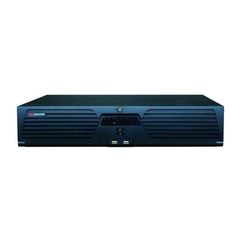
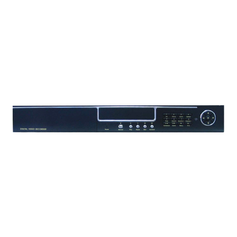
Blackboxav Director DVR Owner's manual

M
ANUAL
Programming
Director
DVR

THE SOFTWARE PROGRAMME –SEQUENCE BUILDER
The Software programme is called VDRSEQ and is supplied on 4 x 1.44Mb Floppy Diskettes
To Install
Insert disk 1 into the floppy drive, select START, RUN and type “A:\SETUP” and click on OK or
press ENTER.
Follow the on screen instructions to insert the disks. During disk 2 you will be asked to insert the
destination directory. ENSURE you type “C:\DVRSEQ”. SETUP will create this directory if it does
not exist.
Once the programme has finished installing you will be able to start the programme from the
VDRSEQ1 icon in Programs menu in the Start menu

1
CONTENTS
Introduction Page 2
Record Operation Page 2
Playback Operation Page 2
Sequence Controller Page 3
External Peripherals Page 3
Sequence Builder Page 4
Manual Control Page 4
RS232 Control Panel Page 5
Record/Playback Settings Page 6
Other Control Panel Menus Page 7
DVR Commands Page 8
Touch screen Page 9
Logic Controller Page 9
Relay Box Page 9
Buttons Page 9
Other Sequence Builder Menus Page 10
Tutorial 1 Page 11
Tutorial 2 Page 13
Tutorial 3 Page 14
Tutorial 4 Page 15
Tutorial 5 Page 16
Tutorial 6 Page 17
Tutorial 7 Page 19
Specifications Page 20
Connections Page 21
Schematic of rear panel showing possible peripherals connected Page 22

2
INTRODUCTION.
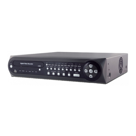
The Black Box AV Director DVR blends the simplicity of a standard video tape recorder with the
versatile control features of a digital record and playback machine. The DVR can operate under simple
manual control via the hand controller but, when programmed via the Sequence Builder, the DVR
becomes a complete ‘Show Control’ system with frame accurate control of lighting, mains switching
and general-purpose logic signals.
RECORD OPERATION.
The DVR records a composite PAL video + stereo audio directly onto hard disc.
The live analogue video signal is digitally encoded into a CCIR-656 data stream (720 * 576 @ 25
frames/sec) and then compressed using 'wavelet' technology into frame 'packets' of fixed size. The
stereo audio is sampled (32KHz: 16 bits/channel) via an audio codec and added to the video data to
form a complete a/v frame packet of 128kBytes size. The frame packets are then stored directly to the
hard disc in real time.
The compressed video frame size is controlled by varying the 'compression factor' in response to the
amount of detail present in the picture. A servo mechanism maintains the best possible picture quality
whilst ensuring that the frame size does not exceed the maximum.
The hard drive is addressed in terms of frames (i.e. 128Kbyte units), and recording can begin at any
point within the total disc space. The frames are stored sequentially on the hard drive and a display
readout indicates the current record position in terms of hours:minutes:seconds:frames.
Recording can be started manually from a wired remote control, or via the RS232 computer interface
or via a pre-programmed schedule (real time clock built in).
Time-lapse recording is possible by specifying gaps between captured frames.
A 'long-play' mode allows recording of a single field per frame and storage into 64kByte packets. This
doubles the total record time available on the disc at the expense of a halving of vertical resolution, the
picture quality however is acceptable for many applications.
An 'off-line' audio dub facility allows a separately recorded 'audio only' section to replace the existing
sound track recorded with the video.
PLAYBACK OPERATION.
Playback is the reverse operation of record. The compressed data is decoded into a CCIR-656 data
stream which is fed to a video DAC to provide both PAL encoded composite video and analogue
RGB signals. The audio data is fed back to the codec to reproduce the analogue audio.
Playback can begin at any point on the hard drive containing recorded data. Once again the start point
is defined in terms of hours:minutes:seconds:frames i.e. playback is frame accurate.
Freeze frame, scan forward and back, and slow play are available.
Playback is controlled via the wired remote, the RS232 computer interface or via a pre-programmed
schedule.

3
SEQUENCE CONTROLLER.
The DVR includes a built-in clock/calendar and an automatic sequence controller which allows the
DVR to play pre-programmed sequences either in a fixed loop; in response to external stimuli such as
buttons, touch screens, PIR sensors etc.; or set times of day; or combinations of these.
A 'SEQUENCE BUILDER' program, running under 'Windows 98' is used to develop the sequences
and to download them into the non-volatile memory in the DVR. The DVR can then be set to run
independently of the computer and will faithfully follow its pre-programmed sequence to provide
information, entertainment or product promotion.
The DVR memory can store up to 100 separate sequences, which can be accessed via external
buttons. Each sequence consists of up to 32 steps (or commands) and can be linked to provide longer
sequences if required.
Sequence commands available for controlling the DVR include PLAY FROM (a frame time point),
WAIT UNTIL (a frame time point), PAUSE AT (a frame time point), WAIT FOR (a set number of
frames), WAIT UNTIL (a real time point) and RECORD AT (a frame time point). Also a GO
SEQUENCE (sequence number) command allows a jump to another sequence number.
When the DVR is in automatic mode, it will begin playing sequence 00 as soon as it is switched on and
completed its initialisation (a few seconds). If a simple video loop is all that is required then sequence
00 would contain commands to start at the beginning of the loop, wait until the end frame and then goto
sequence 00 again. The DVR will run constantly like this until switched off or a STOP command is
received from the remote or RS232 inputs.
The DVR also has a built-in button controller, which can read up to 8 buttons via an external 2-wire
connection. Buttons are detected by using different resistors in series with the switches. These buttons
are identified as numbers 1 -8 and will automatically select sequences 1-8 if pressed. This allows
interactive control of up to 8 sequences without the need to purchase external peripheral units. If
required, Black Box AV can supply a circuit board with the necessary resistors and cable/connectors
to facilitate this feature.
EXTERNAL PERIPHERALS.
The DVR has an RS485 interface for connecting other BLACK BOX Director range peripherals.
These include RELAY and LOGIC controllers, MATRIX switches and TOUCH SCREEN
controllers. The peripherals are controlled whilst the DVR is under SEQUENCE operation, and the
'SEQUENCE BUILDER' programme is used to ensure the peripheral operates correctly and at the
right point in the sequence.
The RELAY controller is a 1U rack mounted case, which contains 16 relays, each of which can be
controlled via the SEQUENCE BUILDER to operate at precise frame times during the sequence.
Each RELAY controller is assigned an address, which is unique to the system, and up to 15 RELAY
controllers can be connected to the RS485 bus.
The LOGIC controller is similar to the relay controller but has logic outputs, which can be used to
operate light controllers etc. Similarly up to 15 LOGIC controllers can be connected to the system.
The MATRIX has a matrix of 64 switches each of which is assigned to a particular sequence number.
The MATRIX is used in applications that require more than the 8 built-in switches for sequence
selection.

4
The TOUCH SCREEN interface allows rectangular areas of a flat display screen to be assigned as
buttons for selecting sequences. The SEQUENCE BUILDER software has a control which simplifies
the operation of defining the button area and assigning a sequence number to it. Up to 20 buttons are
allowed per screen. The normal operation when using the TOUCH SCREEN is to display a still image
containing the buttons via the PAUSE AT command and then waiting until a button is touched before
jumping to the desired sequence.
SEQUENCE BUILDER.
This is supplied with the DVR and runs on a PC under Windows 98.
It allows sequences to be built, tested and down loaded to the DVR connected via an RS232 cable.
Sequences can be saved on the computer for future use.
A DVR control panel allows manual operation of the DVR just like a normal video recorder and a
position display gives the current frame in terms of hours:minsutes:seconds:frames.
A COPY facility allows recorded sections to be copied to different parts of the hard drive to permit
some degree of editing.
An AUDIO DUB feature allows the stereo audio track to be replaced with a separately recorded
audio only track.
The software sets the real-time clock in the DVR and can temporarily alter some record parameters
such as 'minimum compression setting' and 'fine detail'. The 'Time Lapse' frame record interval may
also be set.
MANUAL CONTROL.
There are 2 methods of manual control of the DVR. One uses the wired remote hand controller and
displays via the DVR front panel display. The other method is via the RS232 link using the BBDVR
control panel.
The Hand Controller consists of 8 buttons (1-8) and a slider switch. With the slider switch in the
‘Command’ position the buttons operate as the normal command buttons of a video recorder, with the
switch in ‘Sequence’ position AND the DVR in AUTO mode the buttons select sequences 1-8
respectively.
In ‘Command’ mode, the buttons have the following functions: -
1 -RECORD (only available when the DVR displays a ‘GoTo’ address).
2 -STOP.
3 -PLAY.
4 -PAUSE+.
5 -PAUSE-(or time increment for GoTo address).
6 -SCAN BACK (or decrement the GoTo address).
7 -SCAN FORWARD (or increment the GoTo address).
8 -GoTo.

5
Manual Record.
Just as with a video tape recorder where you set the start point to record by winding the tape forward
or back, then with the DVR you also need to set the start point of any video record session. The
difference however is that there is no tape winding involved, you merely enter the start point in terms of
hours:minutes:seconds:frames by pressing the ‘GoTo’ button (8). The top line of the display shows
GoTo HOURS and the current address is on the bottom line. Use the ‘SCAN FORWARD’ (7) and
‘SCAN BACK’ (6) buttons to select the hour. Press (8) again for minutes and adjust with (7) or (6).
Repeat for seconds and frames if necessary. Note if you press the ‘GoTo’ button (8) whilst the display
shows frames you will exit the ‘GoTo’ address routine and the record will be cancelled. If you need to
go back to hours, minutes etc. you can do this by pressing ‘PAUSE-’ (5) which steps through all 4
increments without cancelling ‘GoTo’.
When the address displayed is correct, press ‘RECORD’ (1) to begin recording. Note that the
‘RECORD’ button is ONLY enabled when GoTo is displayed.
During the recording, the ‘STOP’ (2) and ‘PAUSE+’ (4) buttons are enabled. ‘STOP’ ends the
recording, ‘PAUSE+’ (4) will cause the hard disc address to freeze at the (current address + 1), if you
press (4) again, the address will move on 1 frame -this feature allows you to manually ‘grab’ individual
frames.
Manual Playback.
Playback is similar to record except that if you press ‘PLAY’ (3) whilst not in the GoTo mode the
playback begins from address 0:0:0:0. The ‘PAUSE+’ (4) button will pause playback at the current
address with a still image on screen and the audio muted, repeated pressing increments the address and
holding the button pressed will give a slow play. The ‘PAUSE-’ (5) button will operate when the
playback is paused, repeated pressing will then select the previous frames for display, holding the
button pressed gives a slow reverse play.
The ‘SCAN FORWARD/BACK’ buttons (6) and (7) operate in PLAY mode only.
You can use the GoTo address feature for both ‘PLAY’ and ‘PAUSE+’ buttons either from STOP or
during PLAY.
RS232 CONTROL PANEL.
This is part of the ‘SEQUENCE BUILDER’ Windows program and requires the RS232 cable
connection from the DVR to the COM1 connector of a PC running Windows95 or later.
The control panel is selected from the ‘DVR’ menu of the main screen.
Operation is similar to the hand controller except that the GoTo address is entered directly in the boxes
displaying H:M:S:F time. The ‘RECORD’ button is permanently enabled when in the ‘STOP’ mode,
you do not need to enter a new address, the recording will begin from the currently displayed address.
There is no ‘PAUSE-’ button, also the ‘SCAN FORWARD/BACK’ buttons when pressed are
latched so that scan play continues until either PLAY, PAUSE or STOP is pressed.

6
The coloured panel above the mode display window is used to select between
STANDARD/LONG/AUDIO ONLY record. Click on this panel when in STOP mode to change the
type of recording, the default is STANDARD, which will appear a few seconds after issuing a STOP
command. To make a recording, ensure the correct record type is displayed and that the time position
displayed is correct, then click RECORD. The PAUSE and STOP buttons are available to interrupt
the record session. The AUDIO ONLY recording is always performed at standard frame rate.
For playback, the V.PLAY button will play both video and audio, the A.PLAY button is for AUDIO
ONLY play but will also playback the soundtrack from a video recording. During audio play the DVR
video out is a colour bar screen. The coloured panel will indicate the current playback mode as
determined from the data read from the hard disc.
The DISC 1 / 2 option buttons are for DVR systems fitted with removable second drives. If your
system does not have a removable drive always ensure that DISC 1 is selected.
Record/Playback Settings.
The ‘Settings’ menu allows some control over the record and playback parameters. The ‘Quality’ and
‘Detail’ settings control the video compression servo mechanism during record. ‘Quality’ is a number
between 1 (low quality) and 32 (maximum quality) and it sets a limit on the compression factor applied
to the video data. ‘Detail’ goes from 1 (low detail) to 8 (maximum detail) and restricts the high
frequency components of the image. Neither figure equates to any standard unit but they can be used
to apply arbitrary limits on the picture record quality. Their main purpose is to overcome record
problems due to excessive detail or timing ‘jitter’ in the source video such as recording from VHS
where the highest frequencies are generally tape noise.
During record the actual ‘quality figure’ applied depends upon the amount of detail in the image, and
this will vary during a record session. As an aid to analysing the recorded quality, the compression
figure used on each frame is displayed in the ‘Settings’ panel as (Comp -xx) where xx directly relates
to ‘Quality’. This is displayed during both record and playback.
When the DVR is first switched on ‘Quality’ and ‘Detail’ default to 30 and 7 respectively which are
reasonable values for most good quality images, however both can be set at any time, even during the
record process. Suggested values for VHS are Quality -25, Detail -6.
There is a delay between sending a new record setting to the DVR and it being displayed in the
Settings panel. This is because the settings data is transmitted back from the DVR once every few
seconds.
The ‘Scan Rate’ setting is used in playback to set the scan forward/back speed. The SCAN function
effectively pauses at a new frame every 200mS, and the control panel uses the Scan Rate setting as the
number of frames to jump (forward or back) between each pause.
The ‘Interval Time’ setting is used in ‘Time Lapse’ recording/playback to define a time between
grabbing video frames. The interval time is specified in mS and can be between 500 -999999ms.

7
Other Control Panel Menus.
The ‘Time Lapse’ menu is used to start time-lapse record or playback. For record, firstly set the
‘Interval Time’ from the Settings menu, the STANDARD/LONG record type, and the start time point,
and then click ‘Begin Record’ from the Time Lapse menu.
The ‘DVR Copy’ menu allows portions of recorded video to be copied to another section of the hard
disc or, if a removable drive is fitted, to an external system. Also an ‘Audio Dub’ feature is included
which allows the replacement of the audio track with another audio recording on the hard drive
provided they are both done at STANDARD rate.
The copy works by defining the start and end frames of the section to be copied and also the
destination address of the 1st frame to be replaced.
To copy a section, firstly click on ‘DVR Copy’ then ‘Load Times’ to display the ‘Copy Times’ frame.
Enter the start point in H:M: S:F and click ‘Start Time’ in the ‘Copy Times’ frame. Enter the end point
and click ‘End Time’. Enter the 1st frame of the destination address and click ‘Destination’. Remember
to select the appropriate Disc 1 / 2 button. When the start, end and destination times are correct, click
‘Copy’ on the ‘Copy Times’ frame. Note, if after a few seconds, the copy has not started click ‘Copy’
again, however allow a few seconds for the transmission of the times and the start copy command.
During the copy process, the copy address is displayed in the status windows.
For an AUDIO DUB you define the start and end points for the new audio, the destination is the 1st
frame of video where the new audio will begin. Click ‘DUB’ to begin the copy.
How Does The DVR Play A Programmed Sequence?
Essentially, when running under Sequence Control, the DVR will read 1 sequence step from memory
each time a frame of video is displayed. The DVR will then execute that step and move on to the next.
Some steps are executed in one frame time e.g. the ‘PLAY FROM’ command to jump to a new
address, other commands require the DVR to wait at this step until some event e.g. the ‘WAIT FOR’
command where the DVR waits a specified number of frames to elapse before moving to the next step.
Some steps are not instructions specifically for the DVR but are intended to command the peripheral
devices such as ‘TOUCH SCREEN’ or ‘LOGIC CONTROLLER’. These are also executed during
one frame period.
By placing the steps in the correct order, a logical sequence of commands can be built which will
produce a ‘Show Sequence’ combining video, audio, lighting effects etc. all operating with ‘frame
accuracy’ precision.
Some commands enable buttons, which allow jumps to other sequences thus making a completely
interactive system which is simple to create and maintain.
The key to creating a perfect ‘show sequence’ is the Sequence Builder software. It has commands for
controlling the DVR, a TOUCH SCREEN, LOGIC CONTROLLERS, RELAY BOXES and the
BUTTON MATRIX. A description of each command follows and examples of how to use the
commands in a sequence are given below in the tutorial sections.

8
DVR Commands.
1. PLAY FROM -. This command causes the DVR to play from the specified time point. It will also
cause a jump to the new time point if already playing. A special case is PLAY FROM -00:00:00:00,
this should ONLY be used after a PAUSE command since it causes the DVR to resume playing from
its current position. If you wish to start playing from the beginning of the hard disc then use PLAY
FROM -00:00:00:01 and this will begin at the second frame on the disc.
2. WAIT UNTIL -. This command should ONLY be used when the DVR is in PLAY. It causes the
DVR to wait until a frame time point equal to, or greater than, that specified is encountered, at which
point the programme will continue to the next step. Obviously, if the DVR is not playing then the
controller will wait indefinitely.
3. PAUSE AT -. This command causes the DVR to jump to the specified time point and pause with a
freeze frame displayed. The command will be executed wether the DVR is in play, pause or stopped.
There are many uses for this command amongst the most common are to create a slide show, or to
display a still image containing ‘soft buttons’ for the TOUCH SCREEN controller. The special case of
PAUSE AT -00:00:00:00 is useful as it causes the DVR to pause at its current time point without
having to specify the exact time. You should only use the special case at a point where you know the
DVR is playing i.e. don’t use it as the first play/pause command in a sequence.
4. WAIT FOR -. This command causes a simple wait for a specified number of frames. This is the
safest and simplest way to provide a delay, it does not require the DVR to be playing and will count
frames even if the DVR is stopped e.g. if you needed a delay to control the RELAY BOX without the
DVR playing, you can use ‘WAIT FOR’. It is also used to keep the DVR in PAUSE for a set time.
5. HALT AT -. This command will cause the sequence to end when a time point equal to, or greater
than that specified is encountered e.g. HALT AT -00:10:00:00 will cause the sequence to halt when a
frame number >= 00:10:00:00 is encountered. The special case of HALT AT -00:00:00:00 will
immediately halt the sequence. The DVR will then also exit the automatic operation mode and will not
start again until a sequence number is started manually.
6. GO TO SEQUENCE -. This command will cause an immediate jump to the start of the next
sequence specified e.g. GOTO SEQUENCE 01 will jump to the start of sequence 01.
7. SEQ BUTTONS -. This command is used at the start of a sequence to enable/disable any of the 8
sequence buttons. If the command does not appear in a sequence then it is assumed that all 8 sequence
buttons are enabled. The main purpose of the command is to allow or disallow re-entry of a sequence
once started i.e. assume sequence 01 has the command to disable button 1, then once sequence 01 is
started, it cannot be re-started with button 1 until the sequence ends.
8. RECORD FROM -. This command will cause the DVR to begin recording from the specified time
point, provided the DVR is in ‘STOP’ or ‘PAUSE RECORD’ mode. The command is included to
allow timed recording i.e. you precede the command with a WAIT DATE/TIME or WAIT FOR
command and then the recording will begin at a specified time.

9
9. WAIT DATE -. This command causes a wait until the clock/calendar shows a date equal to or
later than that specified. Its main use is for timed recording.
10. WAIT TIME -. This command causes a wait until the clock/calendar shows a time equal to or
later than that specified. Its main use is for timed recording but could be used to trigger a special
sequence at certain times of day.
TOUCH SCREEN (requires a suitable touch screen interface from Black Box AV)
There is only 1 command for this peripheral, it defines the position and size of a ‘soft button’ on the
screen and assigns a sequence number to be played when that button is pressed. See the ‘How to.’
section for information on programming this command. Up to 20 buttons may be defined for a
sequence, each button requiring a single step to define. It is usual to define all the buttons required at
the start of a sequence and then to PAUSE the DVR at the frame displaying the buttons on the screen.
The PAUSE command should be followed by a WAIT FOR command to hold the buttons on the
screen for the required time. If this is the only button screen in the show then follow the wait command
with a GOTO SEQUENCE command to jump back to the start of the sequence and reload the
buttons again.
Each time a new sequence starts, all the touch screen data is cleared, so if you intend a jump to another
touch screen frame after this one, then you need to load all touch buttons required for that sequence.
LOGIC CONTROLLER.
Each logic controller controls a bank of 16 logic signals and up to 15 banks may be connected to the
system. It requires one sequence step to programme one logic bank. See the ‘How to ..’ section for
information on programming the logic signals.
RELAY BOX.
Each relay box controls a bank of 16 relays and up to 15 banks may be connected to the system. It
requires one sequence step to programme one relay bank. See the ‘How to.’ section for information
on programming the relay boxes.
BUTTONS.
This is a matrix of 64 buttons, which are programmed in 4 banks of 16 buttons. Each button has a set
sequence number assigned to it starting with sequence 11 for matrix button 1, through to sequence 74
for matrix button 64. Individual buttons may be enabled/disabled at the start of each new sequence. By
default, all matrix buttons are disabled at the start of each sequence.

10
OTHER SEQUENCE BUILDER MENUS.
The TIME MENU is used to set the date and time in the DVR real time clock. If you click on ‘Set
Time’ then the DVR clock will be synchronised with the clock in your computer. Similarly ‘Set Date’
will set the DVR date to that set in the computer.
The CONFIG menu selects between COM1 and COM2 as the computer serial port for the RS232
link. Whichever port number you select is saved in the ‘dvrseq.cfg’ file so that you do not need to reset
it the next time you run ‘Sequence Builder’.
The DVR menu has 4 options.
‘Send’ will download the currently loaded sequence to the DVR.
‘Play’ will play a sequence on the DVR.
‘Control Panel’ will open the DVR control panel for manual operation.
‘Clear Memory’ will begin a clear sequence memory operation. This is included to allow you to set all
sequences from 01-99 with the same ‘GOTO SEQUENCE 00’ command. This should be done each
time you re-programme a DVR for a new project. Take care; this command will destroy all existing
programmes in the DVR.

11
TUTORIALS
Tutorial 1. How to use Sequence Builder to create a video loop -which plays constantly from
start-up.
1.0 For this we define a new sequence, which contains the start point of the displayed video, the
end point and a jump back to the start.
The sequence will be saved as a file on the computer and then down loaded to SEQUENCE 00 as this
is automatically started when the DVR is switched on.
1.1 Using the manual controls, record about 1 minute of video starting at time point 0:0:0:0. Play it
back to ensure it recorded correctly.
1.2 Using the PLAY, SCAN, PAUSE controls find and note the frame point you wish to
be the start of the displayed video (say 00:00:02:00). Also note the end frame point where you want
the DVR to loop back. For the test just use a 10 second video loop.
1.3 On the Sequence Builder screen, click ‘New’ on the File Menu.
1.4 Click on ‘New’ under the ‘Event’ label.
1.5 The ‘Device/Command’ window opens, click on DVR in the ‘Device’ column.
1.6 The DVR commands are displayed, click on ‘PLAY FROM’ in the ‘Command’ column.
1.7 The ‘Get Video Frame Time’ window is displayed. Enter the START time as H:M:S:F i.e.
00:00:02:00. Click ‘O.K.’ when the start frame time is correct. Don’t enter a start time of 0:0:0:0, this
is a special case (RESUME PLAY).
1.8 The 1st command (step 00) is entered into the sequence builder table, and ‘End’ is displayed
on the next line.
1.9 Click on ‘End’ to enter the next step.
1.10 Once again, the ‘Device/Command Selection’ window opens, click on DVR in the device
column.
1.11 The DVR commands are displayed, click on ‘WAIT UNTIL’ in the ‘Command’ column.
1.12 The ‘Get Video Frame Time’ window is displayed. Enter the end frame of the video loop i.e.
00:00:12:00 for a 10 second loop. Click ‘O.K.’ when ready.
1.13 The second command (Step 01) is entered in the ‘Sequence Builder’ table.
1.14 Click on ‘End’ to enter the next step.
1.15 Click on DVR in the ‘Device/Command Selection’ window.

12
1.16 Use the down scroll button to display ‘GO TO SEQUENCE’ in the ‘Command’ column
and click on ‘GO TO SEQUENCE’.
1.17 The ‘Next Sequence’ window is displayed with ‘00’ displayed as the next sequence. In this
instance we want the DVR to jump back to sequence 00, so the default number is correct, however
we could enter any number between 00 and 99 at this point. With the next sequence number of ‘00’
showing click ‘O.K’.
1.18 The ‘Sequence Builder’ table now shows the complete looping sequence. We should save this
under a unique filename.
1.19 From the ‘File’ menu, select ‘Save As’.
1.20 The ‘File Selection’ window opens with the cursor flashing in the ‘Enter File Name’ box. Enter
the new filename (say dvrloop1) but do not enter an extension, the programme will automatically add
the ‘seq’ extension. Click ‘O.K.’ when ready.
1.21 Notice that the filename has appeared in the ‘Sequence Builder’ window. We are now ready
to send the sequence to the DVR.
1.22 Click on the ‘DVR’ menu on the ‘Sequence Builder’ screen.
1.23 Click on ‘Send’, the ‘DVR’ window prompts you to enter the sequence number to send to (00
-99). Since the window opens with sequence 00 as the default, we do not need to change it this time.
Click ‘O.K.’ when ready.
1.24 The ‘DVR’ window then displays ‘SEQ00’ as the sequence to send to, a ‘CANCEL’ button
to exit the send routine, and the ‘SEND’ button to begin sending. Click the ‘SEND’ button.
1.25 The button colour changes to yellow and the caption shows ‘SENDING’, then ‘CHECK’. If
the send is successful, the button colour returns to grey and the caption to ‘SEND’. If there was an
error, the button will turn red and show ‘FAILED’. Click the button again to retry if the send failed
otherwise click cancel.
1.26 If the send was successful, we can test the sequence by selecting ‘DVR’ from the ‘Sequence
Builder’ menu and click on ‘Play’.
1.27 Once again we are prompted to enter the sequence number, and again the default is ‘00’ so
we just need to click ‘O.K.’ to start the sequence. Hopefully your DVR is playing its 10 second loop
continuously. Try switching the DVR off for a few seconds and then back on to check that the loop
plays continuously from start-up.

13
Tutorial 2. How to edit a step in an existing sequence file.
2.0 This tutorial assumes you have completed tutorial 1 and that you have a sequence file on your
computer ‘dvrloop1’. If you have not created it, please follow tutorial 1 to create the simple looping
sequence. We will edit the ‘WAIT UNTIL’ step to change the loop time.
2.1 From the ‘File’ menu select ‘Open’. The ‘File Selection’ window opens at the default ‘dvrseq’
directory.
2.2 Use the scroll buttons to locate file dvrloop1.seq and ‘double-click’ this filename.
2.3 The dvrloop1 sequence is loaded into the ‘Sequence Builder’ table.
2.4 Use the ‘Save As’ option in the ‘File’ menu to save this with filename “test”.
2.5 Click on the ‘WAIT UNTIL’ step in the ‘Event’ list. The ‘Device/Command Selection’
window opens with ‘DVR’ selected.
2.6 Click on ‘WAIT UNTIL’ and enter the new frame time. Press ‘O.K.’ when ready.
2.7 The new time is entered in Step01.
2.8 We can use the ‘Save’ in the File menu to save this change or ‘Save As’ to save the edited file
under a new name.
2.9 Note we have only changed the sequence file, we have not changed the sequence programmed
in the DVR. We should follow steps 1.22 to 1.27 to download to the DVR and check the new
sequence.

14
Tutorial 3. How to Insert steps in a DVR sequence file.
3.0 Once again we will use the dvrloop1 sequence file of tutorial 1 to illustrate this edit.
3.1 Using the ‘File / Open’ menu, load dvrloop1 into the ‘Sequence Builder’ as in tutorial 2.
3.2 This time we will cause the DVR to PAUSE 5 seconds after the start i.e. time point
00:00:07:00, then wait 5 seconds before continuing to the end of the loop.
3.3 Point to ‘01’ in the ‘Step’ column and click once. Notice 3 buttons appear below the
sequence table.
3.4 With Step 01 highlighted, click on ‘Step Insert’. Notice a new ‘WAIT FOR’ step is inserted
and the last 2 steps are pushed down. This has created a single step which has a minimum 1 frame time
delay.
3.5 Now click on ‘WAIT FOR’ (i.e. step 01) in the ‘Event’ column.
3.6 The ‘Device/Command Selector’ opens and we can edit the new command to be a WAIT
UNTIL time point 00:00:07:00. Note the difference between WAIT FOR (a simple delay of a number
of tics or frames) and WAIT UNTIL (a delay until the current time point is equal to or greater than the
programmed time).
3.7 We now need to enter a ‘PAUSE AT’ command to hold the video paused at this frame.
Single click on 02 in the Step column and click ‘Step Insert’ to insert another new dummy step. Edit
the command at step 02 to be ‘PAUSE AT’ time point 00:00:07:01 i.e. 1 frame after the ‘WAIT
UNTIL’.
3.8 We have now inserted a new pause command in the sequence, We now need a ‘WAIT FOR’
command to give a 5 second delay.
3.9 This time double-click on 03 in the Step column. Notice that this also inserts a dummy ‘WAIT
FOR’ command. Click on ‘WAIT FOR’ in the Event list and edit it for a delay of 5 seconds.
3.10 You should now have steps 00 -05 programmed, however this sequence won’t work because
the ‘WAIT UNTIL’ command will do nothing until it sees a time frame equal to or greater than
00:00:12:00 and we left the DVR in PAUSE at step 02. We need to add a new ‘PLAY FROM’
command after the 5 second delay (step 03).
3.11 Insert a new step immediately before step 04, either by double-clicking 04 in the Step column
or single click and ‘Step Insert’ button.
3.12 Now edit Step 04 by clicking on ‘WAIT FOR’ in step 04. Select ‘PLAY FROM’ and enter
time code 00:00:07:02 i.e. 1 frame on from the current pause position.
3.13 Save this new sequence as dvrloop2, and download it to DVR sequence 00.

15
Tutorial 4. How to Delete and Append steps to an existing sequence file.
4.0 If you have completed tutorials 1-3, then this will be quite simple. Firstly open dvrloop2 from
tutorial 3, and then save it as filename “test”.
4.1 As an example, delete step 03 by clicking on 03 in the ‘Step’ column, then click on the ‘Step
Delete’ button. Notice that this step is deleted and subsequent steps move up 1 place.
4.2 To append additional steps, click on ‘End’ and add new steps as desired.

16
Tutorial 5. How to programme the 8 internal sequence buttons.
5.0 Assume we want to enable buttons 1, 2 and 5 to allow selection of sequences 1,2 and 5 from
sequence 00. This will disable buttons 3,4,6,7,8 whilst sequence 00 is running. We will edit the
dvrloop1 sequence from tutorial 1 and insert the button 1-8 enable command at step00.
5.1 Open the dvrloop1 sequence from tutorial 1.
5.2 Double click on 00 in the ‘Step’ column to insert a new step at position 00.
5.3 Click on ‘WAIT FOR’ in the 'Event’ column and select Device = DVR, Command = SEQ
BUTTONS.
5.4 The ‘Buttons 1-8’ window opens with the eight buttons unhighlighted. Click on buttons 1,2 and
5 to highlight (i.e. enable) them. Click O.K. when ready.
5.5 Step 00 now shows SEQ BUTTONS 1-8 -00010011. The binary number at the end is a
short-hand method of indicating the current setting for the buttons, button 1 is on the right button 8 is
on the left and a 1 indicates the button is enabled.
5.6 Download this to sequence 00 in the DVR.
5.7 We now need to create 3 sequences to play in sequence 01, 02, 05 so that we can test the
button operation. We will use simple 5 second pauses at different time points to distinguish between the
3 sequences.
5.8 Make a sequence consisting of PAUSE at 00:00:11:00, WAIT FOR five seconds, GO TO
SEQUENCE 00. Download this to sequence 01 in the DVR.
5.9 Edit the sequence to pause at 00:00:12:00 and down load to sequence 02. Then edit to pause
at 00:00:15:00 and download to sequence 05.
5.10 From the DVR menu, play sequence 00, which should loop as normal.
5.11 With the hand controller switch set to ‘Sequence’ position, press button 1. Sequence 1 should
play i.e. pause at 11:00 for 5 seconds and then return to Seq 00. The DVR front panel display will
indicate the SEQ / STEP number as it plays.
5.12 Experiment with the sequence buttons and you should find that from sequence 00 only buttons
1,2 and 5 are enabled, however from the other sequences all 8 buttons are enabled. This can result in
selecting sequence numbers that have no valid programme -beware !!.

17
Tutorial 6. How to programme the Touch Screen ‘Soft’ buttons.
6.0 The touch screen requires an interface which connects the touch screen to the ‘AUX’ input of
the DVR. Contact Black Box AV for further information on this interface.
For the DVR, a ‘soft’ button is a rectangular area of screen which, if touched, will cause the DVR to
jump to a particular sequence. Each new sequence can contain up to 20 ‘soft’ buttons. A button is
created by defining the top-left and bottom-right corners and then assigning a sequence number to the
button.
The touch screen could be used with the screen acting as one big button where touching any part
would activate a new sequence, however, for the tutorial, we will define 2 ‘soft’ buttons.
6.1 Firstly ensure the touch screen interface is connected and the DVR is paused displaying the still
image that contains 2 ‘soft’ buttons. If you have not recorded a suitable image, then choose a still
having two distinct areas that could represent rectangular buttons.
6.2 The ‘soft’ buttons are usually programmed as the first steps in a sequence so select ‘New’
from the ‘File’ menu to create a new sequence.
6.3 Click on ‘New’ and select ‘TOUCH SCRN’ as the Device and ‘ADD BUT’ as the
command.
6.4 The ‘Touch Screen’ frame is displayed. This has a button ‘Touch On’ to turn on the
transmission of touch screen data to the computer. The frame also displays the current X,Y
coordinates and has 2 boxes which display the last touch coordinates for Top/Left and Bottom/Right..
Another box holds the sequence number for this button.
6.5 Click ‘Touch On’ to begin the transmission of data -notice the caption changes to ‘Touch
Off’. The X/Y coordinates should be displaying 63/63 -this is the value when the screen is not
touched.
Touch, and move your finger around the screen and you will see the coordinates change. Notice that
the coordinates go from about 05/60 (top/left) to about 60/05 (bottom/right) i.e. 1st coordinate (X)
goes from left to right, 2nd coordinate (Y) goes from bottom to top. Also notice that when the screen
is released, the last touch coordinate is saved in the ‘Top/Left’ box. This is how we define the corners
of the ‘soft’ button.
6.6. Click on ‘Top/Left’ to enter this coordinate. Then touch the screen at the top/left corner of the
1st soft button. Remove the touch and ensure that the correct coordinate is entered in the ‘Top/Left’
box.
6.7. Click on ‘Bot/Right’ to enter the next coordinate. Once again check that the coordinate has
entered correctly.
6.8 Now click on the box containing the sequence number and enter the sequence number you
want this button to select. Enter ‘01’ for this button. Hopefully, if you have completed tutorial 5 you
will have a sequence 01 loaded to test the button.

18
6.9 Click ‘O.K.’, the ‘Touch Screen’ frame disappears and Step 00 is loaded with the ‘soft’
button details. Note that the coordinates are displayed together with the sequence number for the
button.
6.10 Click on ‘End’ and repeat the above steps to create the 2nd ‘soft’ button. This time allocate
sequence 02 to the button.
6.11 Now add a ‘PAUSE AT’ command to display the still frame showing the soft buttons.
6.12 Add a ‘WAIT FOR’ 20 seconds command, followed by a ‘GOTO SEQUENCE -00’.
6.13 Save the sequence as ‘touchtst1’ and send it to sequence 00 in the DVR so that this touch
screen frame will be displayed on switch-on and will refresh itself every 20 seconds.
6.14 Play Sequence 00 and check that the ‘soft’ buttons work correctly.
Table of contents
