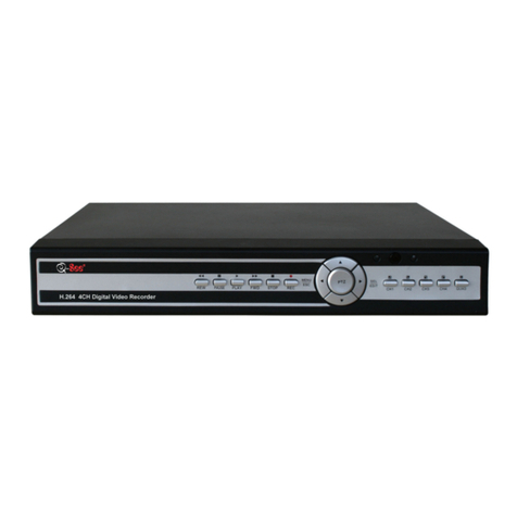
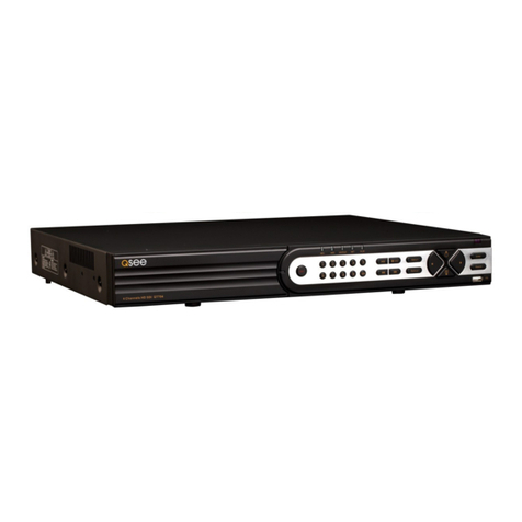
Q-See QSNDVR4R User manual

QSNDVR4R
Digital Video Recorder
U
Us
se
er
r’
’s
s
M
Ma
an
nu
ua
al
l
Rev 061807

4 Channel Digital Video Recorder
1
Precautions & Safety Instructions
Power Source
This Digital-Video-Recorder uses a AC90-240 V power source. This recorder should only be
operated using the specified power supply. Please check the voltage of the power supply
before using.
If you are not going to use the recorder for a long period of time, be sure to disconnect the
power supply from the wall outlet. To disconnect the power supply, grasp the plug itself; never
pull the cord.
On Placement
•This recording unit is to be used and installed indoors. It must not be exposed to rain or
moisture.
•Place the recorder in a location with adequate ventilation to prevent heat build-up in the
recorder. Slots and openings in the cabinet are provided for ventilation to ensure reliable
operation of the recorder and to protect from overheating. These openings must not be blocked
or covered. Do not place the recorder on a soft surface such as a rug that might block the
ventilation holes. Do not place the recorder in a confined space such as a bookshelf or similar
type unit.
•Do not place the recorder in a location near heat sources such as a radiator or heat register.
•Do not place the recorder in a location subject to direct sunlight, excessive dust or mechanical
shock.
Object and Liquid Entry
Should any solid object or liquid fall into the cabinet, unplug the recorder and have it checked
by qualified service technicians before operating it any further.
Servicing
This Digital-Video-Recorder is a precision instrument. Refer all servicing of repairs for
damage or malfunctioning of the recorder to qualified service technicians or contact the dealers
in your area. Do not attempt to make the repairs yourself.
Copyrights
Television programs, films, video tapes, discs, and other materials may be copyrighted.
Unauthorized recording of such materials may be contrary to the provisions of the copyright
laws.

4 Channel Digital Video Recorder
2
Features
Video input: 4 channels; video output: 2
Audio input: 4 channels; audio output: 1
Four optional levels of image quality: very high, high, normal and low. Record and playback
frame rate changeable for recording.
Compression standard: MJEPG
NTSC / PAL compatible.
Supports alarm recording and set times recording.
Multi-function searches: Identifies and sorts various alarm records and time records from routine
recording; search by time, by segment or by event.
Playback modes: pause, variable fast forward and reverse play modes.
Zoom, auto function and PIP function.
USB device backup and update enabled.
Remote control and PTZ control enabled.
Loss and motion detection functions.
Triplex operation, play back and search while recording. Simultaneous display of live and
playback video.
Supports network view.
Supports on-screen watermark security.
Independent from a PC platform. Will not be prone to shutdown and virus infection.

4 Channel Digital Video Recorder
3
TABLE OF CONTENTS
SYSTEM CONNECTIONS.............................................................................5
1.
R
EAR
P
ANEL AND
C
ONNECTION
T
ERMINALS
....................................................................................... 5
2.
V
IDEO AND
A
UDIO
C
ONNECTION
......................................................................................................... 6
3.
A
LARM AND
S
ENSORS
C
ONNECTION
................................................................................................... 7
4.
H
ARD
D
ISK
C
ONNECTION
.................................................................................................................... 9
SYSTEM SETUP............................................................................................10
1.
A
CCESS TO
M
ENU
.............................................................................................................................. 10
2.
S
ETUP
O
PTIONS
................................................................................................................................. 11
3.
S
YSTEM
S
ETUP
.................................................................................................................................. 11
4.
P
ASSWORD
S
ET
.................................................................................................................................. 12
5.
T
IME
/D
ATE
S
ET
................................................................................................................................. 13
6.
HDD
F
ORMAT
S
ET
............................................................................................................................. 14
7.
A
UTO
S
EQUENCE
S
ETUP
.................................................................................................................... 15
8.
F
ACTORY
R
ESET
................................................................................................................................. 16
9.
V
IDEO
S
ETUP
..................................................................................................................................... 16
10.
C
AMERA
N
AMES
S
ETUP
................................................................................................................... 17
11.
B
RIGHTNESS
/C
ONTRAST
S
ETUP
....................................................................................................... 18
12.
R
ECORDING
S
ETUP
.......................................................................................................................... 18
13.
N
ETWORK
S
ETUP
............................................................................................................................. 19
14.
MAC
S
ET
......................................................................................................................................... 20
15.
A
LARM AND
S
ENSORS
S
ETUP
........................................................................................................... 21
16.
M
OTION
D
ETECTION
S
ETTINGS
....................................................................................................... 22
17.
A
REA
S
ET
......................................................................................................................................... 24
18.
USB
S
ET
.......................................................................................................................................... 24
19.
S
CHEDULE
S
ET
................................................................................................................................ 25
20.
P
ROTOCOL
S
ET
................................................................................................................................ 26
FRONT PANEL BUTTONS..........................................................................28
1. R
ECORDING
/P
LAYBACK
C
ONTROL
B
UTTONS
.................................................................................... 28
2.
F
UNCTION
C
ONTROLS
A
REA
.............................................................................................................. 29
3.
C
HANNEL
S
ELECTION
C
ONTROLS
A
REA
............................................................................................ 30
Table of Contents
4 Channel Digital Video Recorder
4
DISPLAY STATUSES WHILE RUNNING.................................................32
1.
S
CREEN
D
ISPLAY
W
HILE
R
UNNING
................................................................................................... 32
2.
S
CREEN
D
ISPLAY
W
HILE
P
LAYING
.................................................................................................... 33
3.
TRIP
D
ISPLAY
................................................................................................................................... 33
USER GUIDELINE .......................................................................................35
1.
T
URNING
ON
THE
DVR..................................................................................................................... 35
2.
T
URNING
OFF
THE
DVR ................................................................................................................... 35
3.
N
ORMAL
R
ECORDING
P
ROCESS
......................................................................................................... 35
4.
A
LARM
R
ECORDING
.......................................................................................................................... 36
5.
T
IME
R
ECORDING
.............................................................................................................................. 37
6.
P
LAYBACK
......................................................................................................................................... 37
7.
S
EARCH
P
LAY
.................................................................................................................................... 37
8.
T
IME
S
EARCH
.................................................................................................................................... 38
9.
E
VENT
S
EARCH
.................................................................................................................................. 39
10.
S
TART
S
TOP
S
EARCH
........................................................................................................................ 40
11.
Z
OOM
O
PERATION
............................................................................................................................ 41
12.
PIP
O
PERATION
................................................................................................................................ 41
13.
I
NFORMATION
D
ISPLAY
................................................................................................................... 42
14.
USB
D
EVICE
B
ACKUP
..................................................................................................................... 43
15.
P
AN
-T
ILT
-Z
OOM
(PTZ)
O
PERATION
................................................................................................. 44
16.
D
EFAULT
S
ETTINGS
.......................................................................................................................... 45
17.
R
EMOTE
C
ONTROL
.......................................................................................................................... 47
18.
S
ERIAL
P
ORT
C
ONTROL
................................................................................................................... 47
19.
PC
V
IEW
S
OFTWARE
I
NSTALLATION
A
ND
O
PERATION
..................................................................... 47
STANDARD AND PRODUCT SPECIFICATIONS...................................53
EQUIPMENT AND ACCESSORIES SUPPLIED......................................54
APPENDIX A: Q&A TROUBLESHOOTING GUIDE..............................55
APPENDIX B: SERIAL PORT PROTOCOL.............................................58
APPENDIX C: RECORDING CAPACITY FOR 120GB HDD ................60

4 Channel Digital Video Recorder
5
APPENDIX D: INTERNET VIEW/PLAYBACK CONFIGURATION...60
S
Sy
ys
st
te
em
m
C
Co
on
nn
ne
ec
ct
ti
io
on
ns
s
1. Rear Panel and Connection Terminals
Power cord, input and output signal terminals are all situated at the rear panel of the DVR. The
connections to monitor(s), video cameras, and all external peripherals are through the terminals and
sockets on the rear panel. The rear view of the DVR is illustrated below.
The rear panel is defined as follows:
1: POWER INPUT (DC12V) 2: VIDEO INPUT 1-4 3: VIDEO OUTPUT
4: AUDIO INPUT 1-4 5: AUDIO OUTPUT 6: USB PORT

4 Channel Digital Video Recorder
6
7: NET INTERFACE 8: ALARM INPUT 9: ALARM OUTPUT
10: +5V 11: GROUND 12: RS485 PORT
2. Video and Audio Connection
The DVR can support up to 4 cameras video input simultaneously. The monitor must be installed as
shown in the diagram below. Install the monitor for system setup, which is described in the next
section.
AUDIO IN
VEDIO IN
VEDIO OUT
VEDIO IN
AUDIO OUT
Microphone
There are two steps for camera installation:
Ⅰ
. Connect the Video Signal Line to the DVR channel input.
Ⅱ
. Connect the power adaptor jack to the camera.
The DVR can connect up to four channels for audio input, but only one can be selected for output
and recording at any given time.
To display the DVR image, the video output signal should be displayed to the TV set or monitor
connected to the rear panel. Any TV set that has a “video input” terminal is suitable for
displaying
the image. The figure above shows the video and audio signal line connection.
Note: Only one audio input can be connected at any time. If audio is connected CAM1, audio to
CAM2 to CAM4 must be unplugged.
VIDEO OUT
VIDEO IN
VIDEO IN
Microphone

4 Channel Digital Video Recorder
7
3. Alarm and Sensors Connection (Requires professional installer)
The DVR can support up to 4 alarms input and 3 alarms output.
Alarm input: There are two types of alarm input.
1. Voltage output
(
5V and 0V
)
A: In case the sensor output is high voltage (5V) normally and output is low voltage when
triggered (0V), then users must set the DVR for low voltage alarm.
B: In case the sensor output is low voltage (0V) normally and output is high voltage when
triggered (5V), then users must set the DVR for high voltage alarm.
Refer to the diagram below; Ch 2 to Ch 4 connectivity is similar to that for channel 1.
2. Open/Close output
A: N.O. Normal Open; closes when triggered. DVR must be set as low voltage alarm.
B: N.C. Normal Close; opens when triggered. DVR must set as high voltage alarm.
Please refer to the diagram below; Channel 2 to Channel 4 are similar to Channel 1.

4 Channel Digital Video Recorder
8
Alarm output
There are three alarm output pins, the status of these pins are illustrated below:
N O
. .
COM
N C
. .
N O
. .
COM
N C
.
.
Before alarm
After alarm
Example for alarm output connection:
N O
. .
COM
N C
. .
Alarm
5V

4 Channel Digital Video Recorder
9
4. Hard Disk Connection
To install the Hard Disk follow the installation sequence illustrated below.
Note: If the DVR comes with a HDD, skip the following steps.
1. Pull out the hard drive rack from the DVR
side panel.
2.
Open the top cover of the drawer.
3. Jump HDD to Master
Jump to Master
4. Connect the ribbon (IDE) cable & power
cable.
5. Close the top cover of the drawer
and
put
the hard drive drawer back into the DVR.
(Make sure the cables are firmly pressed onto
the HDD interface
)
6.
Lock the hard drive draw by turning the
key clockwise.
If you have another HDD, please jump that HDD to SLAVE, open the DVR cover, put the HDD to a
second HDD shelf, and then connect the power and ribbon cables.

4 Channel Digital Video Recorder
10
S
Sy
ys
st
te
em
m
S
Se
et
tu
up
p
Prior to use, program your desired settings, otherwise the DVR will run in the default settings.
1. Access to Menu
To access the menu just press the Menu button in the front panel or the remote and the password input
window will display as shown below.
The password is a random combination of 4 digits, “0-9”. The default is “0000”. For security, as you
input your password, “*” will display. If you input an incorrect password, the PASSWORD CHECK
screen will automatically return. If you don’t want to input the password and give up the operation, exit
the system. To exit the system, it is not necessary to input your password, just press the menu button. To
change the password, refer to “password change”.
After you enter the correct password, the Top Main Menu will display for “SETUP MODE” as
shown below.

4 Channel Digital Video Recorder
11
2. Setup Options
When in SETUP MODE, press on either the UP or DOWN arrow buttons on the remote or front
panel to scroll through the selection of settings. The selection will be highlighted in yellow.
When choosing digital fields such as such as year, month, day, hour, minute, second, etc, press on the
left or right arrow buttons on the remote or front panel.
Press the “+” or “-” buttons to change the value where the cursor stands, press the ENTER button to
enter the sub menu and press the MENU button to return to a previous menu.
3. System Setup
To access System Setup, select SYSTEM SET and click on ENTER. The SYSTEM SETUP window will
appear. This is illustrated below.

4 Channel Digital Video Recorder
12
The following options are available:
(1) TIME/DATE SET (See below)
(2) HDD FORMAT SET (See below)
(3) AUTOSEQUENCE SET (See below)
(4) FACTORY RESET (See below)
(5) PASSWORD SET (See below)
(6) MENU LANGUAGE: Use “+” or “-” to modify this option.
(7) PLAY REPEAT: If set to YES, when playing stored video in the HDD to the end, it will
automatically replay video from the beginning, otherwise stops at the end.
(8) VIDEO SOURCE: To set up the video format, NTSC or PAL
(9) BUZZER SOUND: Buzzer switcher. If set to “OFF”, the buzzer will not work..
4. Password Set
When the cursor moves to Password Set, press the ENTER button and the PASSWORD SETUP window
will appear as illustrated below.

4 Channel Digital Video Recorder
13
①
PASSWORD CHANGE: Press the ENTER button to change the password. The user must enter
the CURRENT PASSWORD first. If the current password is correct, the system will prompt to input the
new password with CHANGE PASSWORD and then input again with CONFIRM PASSWORD. If the
password is changed successfully, the screen will display PASSWORD CHANGED.
②
SETUP PASSWORD: If set to ON means that the user must input the password before entering
the SETUP MODE Top Menu. If set to OFF means that the user can enter the Setup Menu without a
password. Use “+” or “-” to modify this option.
③
SYSTEM PASSWORD: If set to ON means that the user should input the password before
entering the SYSTEM SETUP menu. If set to OFF means that the user can enter this menu without a
password. Use “+” or “-” to modify this option.
④
SCHEDULE PASSWORD: If set to ON means that the user should input the password to stop
Schedule Recording when pressing the Schedule button in the front panel or remote. If set to OFF means
that the user can stop schedule recording without a password. Use “+” or “-” to modify this option.
⑤
RECORD PASSWORD: If set to ON means that the user should input the password to stop
recording when pressing the REC button in the front panel or the remote. If set to OFF means that the
user can stop recording without a password. Use “+” or “-” to modify this option.
Note: If you forget the required password, press the Stop button in the front panel 12 times. This
operation will change the password to the default value “1111”. Similarly, if you enter a wrong
(or forgot the) password when the system prompts the password to access SETUP MODE, press
the Stop button 12 times. This operation also changes the password to its default value.
5. Time/Date Set
When the cursor moves to TIME/DATE SET, press ENTER and the TIME/DATE SETUP window will

4 Channel Digital Video Recorder
14
appear as shown below. Note that if the DVR is in recording mode you cannot access this menu
unless you stop recording first.
.
Press UP, DOWN, LEFT, and RIGHT arrow buttons to move the cursor. Press “+” or “-” buttons in the
front panel or the remote to set up the DATE and TIME values.
•FORMAT: The time display format, which is different for USA, Europe and Asia users.
•DISPLAY: If set to “OFF”, time will not display on the screen.
•LOCAL: Time display position in the cameras’ video output.
6. HDD Format Set
When the cursor moves to HDD FORMAT SET, press ENTER and the HDD Format Setup window will
appear to confirm this operation. This is illustrated below.

4 Channel Digital Video Recorder
15
If YES is selected and ENTER is pressed to confirm, all video files on the HDD will be lost in the
reformatting process. Select NO to skip this operation.
7. Auto Sequence Setup
Auto Sequence will display one camera at a time at specific intervals. Move the cursor to AUTOSEQ
SET in the SYSTEM SETUP menu, press the ENTER button and the AUTO SETUP window will
appear. This is illustrated below.
Press the UP or DOWN arrows buttons to select each channel separately. Press the “+” or “-” buttons

4 Channel Digital Video Recorder
16
to change the Auto Sequence time for each channel.
8. Factory Reset
In the SYSTEM SETUP menu window, select FACTORY RESET then ENTER and a window to
confirm will appear as illustrated below.
If YES is selected and the ENTER button is pressed, the DVR will reset to default factory settings. To
skip this operation, select and enter NO.
9. Video Setup
When the cursor moves to VIDEO SET in the top SETUP MODE menu, press the ENTER button and
the VIDEO SETUP menu window will appear. This is illustrated below. The BOUNDARY
(Boundary Color) and BACK GROUND settings define colors for border lines between split screens and
inactive screens.

4 Channel Digital Video Recorder
17
10. Camera Names Setup
When the cursor moves to NAME SETUP in the VIDEO SETUP window, press the ENTER button and
the cameras NAME SETUP window will appear. This is illustrated below.
Pressing the UP or DOWN arrow buttons will select the channels separately. Press the ENTER button
to change each channel’s name. Each channel’s name is the combination of up to eight characters.
Pressing the LEFT or RIGHT arrow buttons will select each character. Pressing the “+” or “-” button
modifies characters for the name. When the name setup for each channel is complete press the ENTER
button to save the name.

4 Channel Digital Video Recorder
18
DISPLAY: If set to OFF, the channel’s name will not display on the screen.
11. Brightness/Contrast Setup
When the cursor moves to BRI/CON SETUP in the VIDEO SETUP window, press the ENTER button
and the BRIGHT/CONTRAST SETUP window will appear. This is illustrated below.
BRI: Picture Brightness
CON: Picture Contrast
Press the UP, DOWN, LEFT, and RIGHT arrow buttons in the front panel or remote to move the cursor
around to set BRI and CON for each channel. Press the “+” or “+” buttons to modify the intensity
values.
12. Recording Setup
When the cursor moves to RECORD SET in the main SETUP MODE menu, pressing the ENTER
button will result in the RECORD SETUP window appearing. This is illustrated below. Press the up or
down arrow buttons to move the cursor. Press the “+”or “-” buttons on the remote, or in the front panel,
to change the values.
Note: While the DVR is in recording or playback mode, you cannot access this menu unless you
stop recording or playback first.

4 Channel Digital Video Recorder
19
OVER WRITE: If set to YES, the DVR will automatically overwrite the HDD when the HDD is full. If
set to NO, the DVR will automatically stop recording when the HDD is full.
REC SPEED: The DVR factory default setting for the recording frame rate is 30F/SEC (frames/second)
under video standard NTSC (25F/SEC default under video standard PAL). This means the DVR
records events at the speed of 30 frames per second. The higher the recording speed rate, the more
natural look is displayed on the screen during playback. The lower the recording frame rate, the more
space is saved on the hard disk. The highest frame rate is 120F/SEC for NTSC (for PAL is 100F/SEC)
when the resolution is set as 360.
REC QUALITY: There are four different video quality settings: LOW, NORMAL, HIGH and VERY
HIGH. The higher the video quality is set, the clearer the images that are obtained during playback. The
lower the video quality is set, the more space is saved on the hard disk drive.
RESOLUTION: The recording picture size of the DVR has two modes: 360 and 720. The default
value is 360. In 720 mode, the recorded picture is twice as large than in 360 mode. In 360 mode the REC
speed is fixed at 120F/SEC for NTSC (100F/SEC for PAL) and the maximum REC SPEED in 720 mode
is 60F/SEC for NTSC (50F/SEC for PAL).
PB SPEED: The default playback frame rate is shown as NO USE, which means that it is the same as
REC SPEED.
AUDIO ENABLE: When set to ON, the DVR will record in one channel. This channel has to be
selected among the four available channels. The default is CH1. The audio signal playback is only
possible through the DVR.
13. Network Setup (May require IT expertise)
When the cursor moves to NETWORK SET in the SETUP MODE Top Main Menu, pressing the
Other manuals for QSNDVR4R
1
Table of contents
Other Q-See DVR manuals

Q-See
Q-See QR4074 User manual

Q-See
Q-See QQTT442288--440033 User manual

Q-See
Q-See QSD9004V User manual

Q-See
Q-See QT426 User manual

Q-See
Q-See QR404 User manual

Q-See
Q-See Prosumer QT528 User manual

Q-See
Q-See QT426 User guide

Q-See
Q-See Prosumer QT528 User manual

Q-See
Q-See QSW1001R User manual

Q-See
Q-See QC40198 User manual

Q-See
Q-See QT454-403-5 User manual

Q-See
Q-See QSD42908C8 User manual

Q-See
Q-See QSNDVR16M User manual

Q-See
Q-See QT SERIES User manual

Q-See
Q-See QSD2316L User guide

Q-See
Q-See QC444-403 User manual

Q-See
Q-See QS434 User manual

Q-See
Q-See QSDF8204C4 User manual

Q-See
Q-See QS434 User manual

Q-See
Q-See Q4DVR4RCM User manual