Blackline Safety Loner Beacon User manual
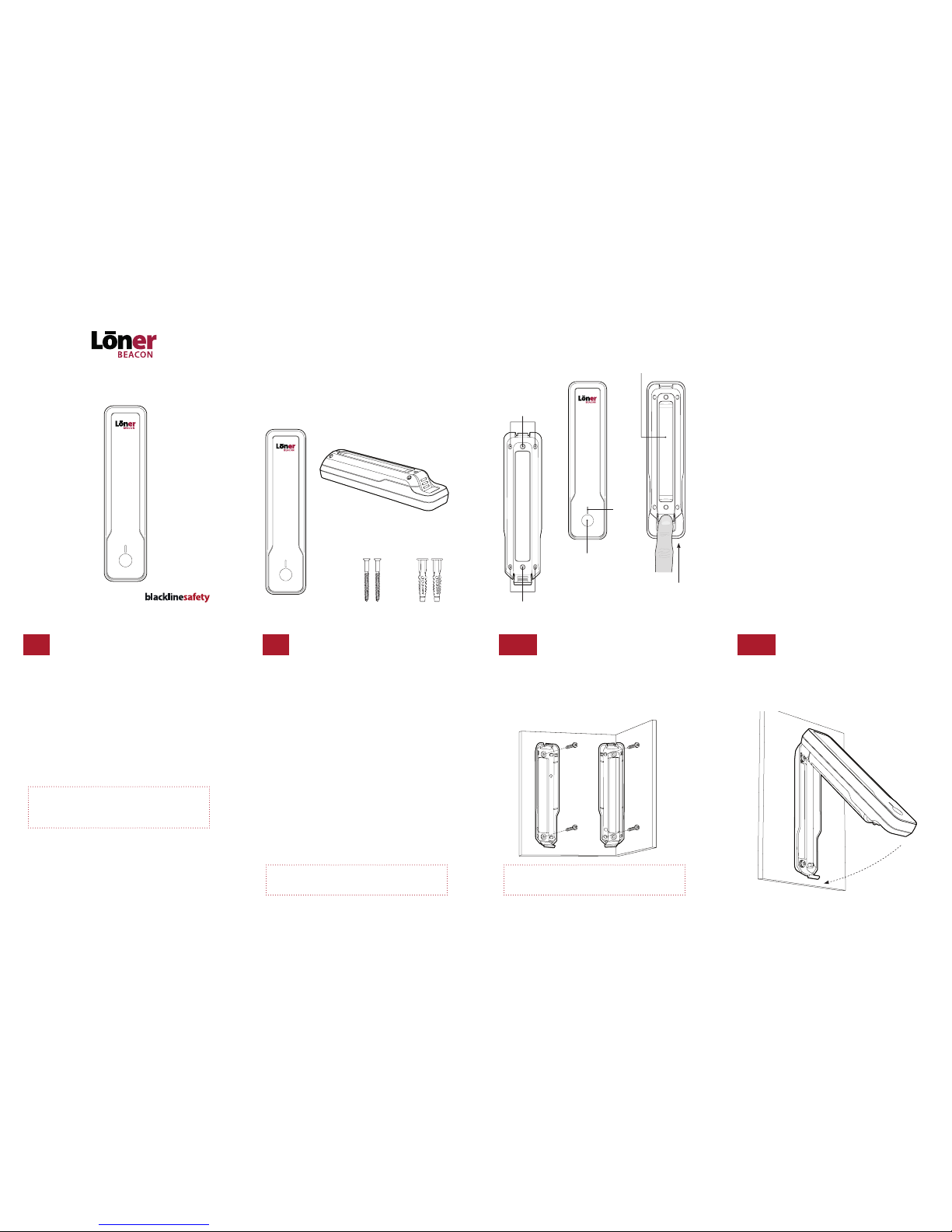
PACKAGE CONTENTS
A. Loner Beacon
B. Loner Beacon mounting bracket (attached)
C. 2 – #6 x 1”screws
D. 2 – Drywall anchors
HARDWARE DETAILS
SUGGESTED INSTALLATION
Select an installation location
§Loner Beacons should be installed wherever GPS signals are
unreliable or unavailable
§By default Loner Beacons will transmit in a radius of about 15
to 30 feet but range is dependent upon obstructions in the
environment and mounting position
§Beacons should be mounted higher up in a room as practical
with minimal obstructions to interfere with the wireless signal
§Continuous coverage of an area is not a requirement, but it is
benecial
§It is ok to have signals overlap. Only the strongest beacon
signal will be used to identify a worker’s location.
§Consider placing Loner Beacons near circulation pinch-points
like doorways, catwalks or gates
§Ensure that areas with poor visual access are adequately
covered—for example behind equipment or piping
§Obstructions that are made of metal or concrete will reduce
signal range compared to wooden structures
02
PRIOR TO INSTALLATION
Information for each Loner Beacon must be entered into your
Blackline Live account to enable indoor positioning.
1. Log in to your Blackline Live account
2. Go to menu > select activate a device under the account
heading
3. Select Loner Beacon under the choose a device drop-down
menu > enter the unit ID and activation code found on the
product label on the back of Loner Beacon (see hardware
details section)
Once Loner Beacon has been activated, installation can commence.
01 INSTALL THE BEACON
1. Remove the mounting bracket from Loner Beacon
2. Place the mounting bracket in the desired mounting location
with indication arrow on the inside of the bracket pointing
upward. Mark the position of two of the mounting holes
3. Prepare the mounting surface with pilot holes and the installation
of drywall anchors as appropriate
Product label
HOW LONER BEACONS WORKS
§Loner Beacons transmit a low energy signal to compatible
Loner® devices that are within range
§Blackline Loner employee-worn devices report Loner Beacon
ID to the Blackline Safety Network to map the user’s location
§Loner Beacons have a default transmit radius of approximately
15 to 30 feet (transmit level 1), depending upon obstructions in
the environment and mounting position
Loner Beacon prerequisites
§A pre-existing Blackline Live user account:
live.blacklinesafety.com
§One or more Loner Beacon-compatible devices (Loner SMD/
IS+/900 safety monitoring devices) activated in the Loner
Portal account
§Loner Beacon location and naming information for each
installed beacon added to the Blackline Live user account
Installation Guide Bracket
mounting
holes
Bracket mounting holes
Power/status
button
Press up
to release
bracket
Power/
status
light
A
B
C D
The Loner Beacon bracket enables mounting on a wall or
in a corner.
4. Mount the bracket in place using the supplied screws
5. Hook Lone Beacon on the top of the mounting bracket and
snap it onto place
IMPORTANT
During installation, take care to note the Unit ID and location
of each beacon that you install.
03a 03b
For highest accuracy install more Loner Beacons operating at
lowest transmit power setting. See transmit power settings.

TURNING ON THE BEACON
Loner Beacons are shipped with batteries installed and powered o.
1. Press the power/status button to turn on—
the status light will illuminate. Loner Beacon
is now ready to use.
Green Status Light
Indicates normal operation
Red Status Light – Flashing
Indicates a low battery
Red Status Light – Solid
Indicates a fault
The status light sleeps 2 minutes
after the last button press to conserve
energy while operating.
At any time, pressing the power/status button
will wake up the status light and it will remain
on until going to sleep again.
To power o Loner Beacon
1. Press and hold the power/status button until the green status
light turns o
TRANSMIT POWER SETTINGS
The transmit power level aects the range of Loner Beacon
signals. Loner Beacons are shipped in the lowest transmit power
setting which is appropriate for most installations.
To change the transmission power setting
1. Press and continue to hold the button on Loner Beacon. The
status light will turn on and then o. Continue to hold the
button. The light will begin to blink in sets of ashes that
indicate power levels.
2. Release the button during the desired set of ashes to pro-
gram your desired power level. The Status Light will repeat
the selected power setting 3 times before returning to normal
operating mode.
The set with 2 ashes indicates the lowest power level and the
set with 5 ashes indicates the highest power level. The sets will
cycle from lowest to highest as you continue to hold the button.
vThe default Loner Beacon transmit level is Level 2, that
provides about 15 to 30 feet line of site signal coverage.
0504
Declaration of Conformity
Blackline Safety hereby declares that this product incorporating Radio and Telecommunications
Terminal Equipment functionality is in compliance with the essential requirements and other
relevant provisions of Directive 1999/5/EC. A copy of the original Declaration of Conformity is
available at: www.blacklinegps.com/ce
FCC Compliance
This equipment has been tested and found to comply with the limits for a Class B digital device,
pursuant to part 15 of the FCC rules. These limits are designed to provide reasonable protection
against harmful interference in a residential installation.
Operation is subject to the following two conditions: (1) This device may not cause harmful
interference, and (2) this device must accept any interference received, including interference
that may cause undesired operation. Changes or modications not expressly approved by the
manufacturer could void the user’s authority to operate the equipment.
This equipment generates, uses and can radiate radio frequency energy and, if not installed
and used in accordance with the instructions, may cause harmful interference to radio
communications. However, there is no guarantee that interference will not occur in a particular
installation. If this equipment does cause harmful interference to radio or television reception,
which can be determined by turning the equipment o and on, the user is encouraged to try to
correct the interference by one or more of the following measures:
• Reorient or relocate the receiving antenna.
• Increase the separation between the equipment and receiver.
• Connect the equipment into an outlet on a circuit dierent from that to which the
receiver is connected.
• Consult the dealer or an experienced radio/T V technician for further assistance.
Industry Canada Compliance
This device complies with Industry Canada licence-exempt RSS standard(s). Operation is subject to
the following two conditions: (1) this device may not cause interference, and (2) this device must
accept any interference, including interference that may cause undesired operation of the device.
IMPORTANT
An eective response to an emergency situation depends
upon the accuracy and completeness of this information.
IMPORTANT
Return Loner Beacon to the same location that it was
removed from.
Use only approved batteries to maintain intrinsic safety
certication as mentioned in this guide.
Copyright © 2016 Blackline Safety Corp. All rights reserved.
Except as expressly provided herein, no part of this manual may be reproduced, copied,
transmitted, disseminated, downloaded, or stored in any storage medium, for any purpose
without the express prior written consent of Blackline Safety Corp. (“Blackline Safety” or“Blackline”).
Blackline hereby grants permission to download a single copy of this manual onto some form
of electronic storage medium to be viewed and to print one copy of this manual or any revision
hereto, provided that such electronic or printed copy of this manual must contain the complete
text of this copyright notice. Further, any unauthorized commercial distribution of this manual or
any revision hereto is strictly prohibited.
The Blackline GPS families of related marks, images and symbols, including Loner, Loner IS+,
Loner SMD, Loner 900, Loner Mobile, UltimateSense, Protect. Share. Connect. and Blackline GPS are
the exclusive properties and trademarks of Blackline Safety Corp. All other brands, product names,
company names, tradezmarks and service marks are the properties of their respective owners.
Warranty
Your Blackline Beacon is warranted against defects in materials and workmanship for up to one
year from date of purchase. For further details regarding your Blackline warranty, please refer to
your Terms and Conditions of Service.
More Information and Support visit: www.blacklinesafety.com for more information.
Information in this document is subject to change without notice. This document is provided
“as is”and Blackline Safety Corp. (“Blackline Safety” or“Blackline”) and its aliated companies and
partners assume no responsibility for any typographical, technical or other inaccuracies in this
document. Blackline reserves the right to periodically change information that is contained in this
document. However, Blackline makes no commitment to provide any such changes, updates,
enhancements or other additions to this document to you in a timely manner or at all.
AFTER INSTALLATION
Assigning Loner Beacon locations in Blackline Live
Once Loner Beacon has been installed,
1. Log into your Blackline Live account.
2. Go to menu > select Beacon setup under the features heading.
3. Add the following information for each activated Loner Beacon:
Name
This should be a friendly name that identies the location
(e.g. Main Floor Entrance).
Site Address
This should be the street address of the nearest entrance to the
site where the corresponding Loner Beacon is installed.
Longitude & Latitude
This should represent the actual location of the installed Loner
Beacon as closely as possible. The pin on the map can be
dragged to automatically calculate the longitude and latitude.
06a 06b
2. Remove the 4 screws on the back of Loner Beacon to remove
the backside of the enclosure to access the batteries.
3. Install new batteries and reassemble Lone Beacon. Battery
orientation is indicated beneath the batteries on the inside of
the front half of the enclosure.
CHANGING BATTERIES
The Loner Beacon’s 2 C-cell batteries last up to ve years at the
highest transmit power setting. When the status light ashes red
every 30 seconds, the battery capacity is at 10% remaining and it
is time to replace the batteries.
1. Remove Loner Beacon from the mounting bracket.
2. Remove the 4 screws and the
backside of Loner Beacon
3. Install the batteries
1. Press up to release the Beacon
from the mounting bracket
07
Lowest Level to Highest Level
Green Transmit Power Lights – Sets of ashes
Level 4Level 3Level 2Level 1 The Blackline Live account will provide a low battery indication
for beacons that have been seen by Blackline Safety monitoring
devices recently.
Loner Beacon, formerly named ANThill, is certied intrinsically safe.
102128_R4
Intrinsically Safe
Loner Beacon
Model: 102140
Sira 16ATEX2232
This equipment complies with EN 60079-0:2011/A11:2013 and EN 60079-11:2012
Ex ia IIC T4 Ga
Ambient operating range -40°C to + 55°C
WARNING USE ONLY THE FOLLOWING BATTERIES
Duracell Procell PC1400
Energizer Industrial EN 93
Rayovac UltraPro 814
WARNING DO NOT REPLACE BATTERY WHEN AN EXPLOSIVE ATMOSPHERE IS
PRESENT, WHEN REPLACING THE CELLS, THE USER SHALL ENSURETHAT BOTH
CELLS ARE THE SAME TYPE, NEW AND UNUSED
Manufactured by:
Blackline Safety
Suite 101, 1215 – 13 St SE
Calgary, Alberta T2G 3J4 Canada
0518 II 1G
ERP# 102129
0162/R1/2016-09-02
Table of contents


