Blackrock Microsystems CerePlex E Series User manual

Manufacturer
630 Komas Drive | Suite 200
Salt Lake City | UT 84108 | USA
P +1 (801) 582-5533 | F +1 (801) 582-1509
www.blackrockmicro.com
Revision 4.00 / LB-0545 – CerePlex E IFU – 2020/11
© 2020 Blackrock Microsystems, LLC
CerePlex E
PN: 7513, 10511 – E96
PN: 8010, 10510 – E128
PN: 10747 – E256
Instructions for Use

Revision 4.00 / LB-0545 – CerePlex E IFU
© 2020 Blackrock Microsystems, LLC
2
Table of Contents
What this Manual Covers ...................................................... 3
Intended Use and Indications for Use ................................... 3
Warnings and Precautions .................................................... 4
Warnings ........................................................................................ 4
Precautions ..................................................................................... 5
Specifications ........................................................................ 6
Hardware ............................................................................... 7
Blackrock CerePlex E Setup ........................................................... 7
Instructions for Assembly ................................................................ 9
CerePlex E Channel Mapping ....................................................... 11
Description of Switches on the CerePlex ...................................... 11
Impedance and Recording Selector Switch ................................ 11
Frequency Range Selector Wide & Norm ................................... 11
Reference and Ground Selector ................................................. 11
R1 and R2 Reference Selector ................................................... 12
Cleaning & Maintenance Instructions .................................. 13
Sterilization ................................................................................... 13
Cleaning and Maintenance ........................................................... 13
Filament Film Disassembly and Replacement .............................. 13
Disposal ........................................................................................ 14
Magnetic Resonance .......................................................... 15
Troubleshooting .................................................................. 15
Return Merchandise Authorization ...................................... 16
Warranty .............................................................................. 17
Support ................................................................................ 17
Complaints .................................................................................... 17

Revision 4.00 / LB-0545 – CerePlex E IFU
© 2020 Blackrock Microsystems, LLC
3
What this Manual Covers
The CerePlex E is a Digital Headstage Accessory that provides a compact interface from
electrodes bonded to a Blackrock CerePort pedestal to the Cerebus or CerePlex Direct
data acquisition systems. The CerePlex E converts analog signals to digital format at the
recording site, which can reduce noise introduced into the signal during transmission to
the recording system.
This Instructions for Use will cover important information about the device including
warnings, hardware settings, and maintenance activities.
There are several CerePlex E models that are available in different channel counts.
These are outlined in the table below.
Intended Use and Indications for Use
The CerePlex E is intended to be used with the CerePort pedestal for animal research
only.
The CerePlex E supports processing and display of biopotential signals from user
supplied electrodes. Biopotential signals include but are not limited to:
Electrocorticography (ECoG), electroencephalography (EEG), electromyography (EMG),
electrocardiography (ECG), electrooculography (EOG) and Evoked Potential (EP).
Model Name
CerePlex E96
v1
CerePlex E128
v1
CerePlex E96
v2
CerePlex E128
v2
CerePlex E256
Model Number
7513 8010 10511 10510 10747
Channel Count
96 128 96 128 256

Revision 4.00 / LB-0545 – CerePlex E IFU
© 2020 Blackrock Microsystems, LLC
4
Warnings and Precautions
Warnings
Only connect Cerebus System components to properly tested, grounded
and dedicated AC outlets to reduce the risk of electrical shock. Do not
use an adapter for ungrounded wall outlets.
Use only the supplied Blackrock Microsystems components (Cerebus™
system, Digital Hub, CerePlex E HDMI Cable).
Substitution of components not supplied by Blackrock Microsystems may
affect system performance and patient/subject safety.
Do not connect the Cerebus System to an outlet controlled by a wall
switch.
Do not use the CerePlex E in the presence of flammable anesthetic
agents.
Keep the CerePlex E away from liquids. Contact with water, shower
spray, or wet surfaces can lead to the subject receiving an electrical
shock.
Connection of external instruments may compromise electrical safety
compliance with IEC 60601-1.
Always use antistatic or electrostatic discharge (ESD) safe gloves when
connecting the CerePlex E.
The CerePlex E digital data cable is long and may snag on equipment in
the room. Secure equipment in place and avoid placing in walkways or
other traffic areas. Pulled cables may cause damage to the CerePlex E
and any other connected devices.
When the CerePlex E is attached to the CerePort pedestal, force applied
to the CerePlex E will be applied to this connector. Avoid large impacts to
the device when it is attached to the subject.
Do not leave the patient/subject connected to the CerePlex E when the
data acquisition system is not in use.

Revision 4.00 / LB-0545 – CerePlex E IFU
© 2020 Blackrock Microsystems, LLC
5
Precautions
Read this entire manual prior to using the device.
Do not allow the digital data cable to be pulled and apply force to the
CerePlex E.
Do not allow any object to impact the CerePlex E while in use.
Do not drop the CerePlex E when handling.
Do not use the CerePlex E with damaged data cables or data cables that
are not supplied by Blackrock, doing so may damage the device.
When replacing the filament film of the device, avoid touching circuit
board components as these can be easily broken and cause damage to
the device.
Do not attempt to use the CerePlex E with connectors other than the
CerePort pedestal connector.
Do not plug the digital data cable into devices other than the Digital Hub
and Blackrock approved headstage accessories.
Avoid spilling fluid onto or into the CerePlex E as doing so may cause
electrical damage to the device and loss of function or electrical shock.
Avoid strong static discharges from sources like televisions or computer
monitors because it can damage the electrical parts of the system.
Using the ‘Wide-Band’ filter mode on the device may cause a reduced
signal to noise ratio. Do not use a washing machine or an automated
washing process (such as an automated washer/disinfector). Doing so
may damage the devices.
Do not allow contaminated devices to dry. All subsequent cleaning and
steps are facilitated by not allowing blood, body fluids, bone and tissue
debris, saline, or disinfectants to dry on used devices.
Avoid overtightening the CerePlex E when attaching to the CerePort
Electrode. Device damage may result.

Revision 4.00 / LB-0545 – CerePlex E IFU
© 2020 Blackrock Microsystems, LLC
6
Specifications
Model Name
CerePlex E
96
CerePlex E128
CerePlex
E256
Model Number
7513/10511 8010/10510 10747
Number of
Channels
96 128 256
Power Re
quirements
0-5 VDC, 150 mA maximum load 0-5 VDC, 300 mA
maximum load
Resolution
16-bit, 250 nV per step
Sampling Frequency
30,000 Samples per Second
Mode of Operation
Continuous
Input Hardware Filter
Normal Mode:
0.3 Hz (1st Order) – 7.5 kHz (3rd Order)
Wide-Band Mode:
0.02 Hz (1st Order) – 10 kHz (3rd Order)
Input Filter Type
Butterworth
Input Impedance
1300 MΩ @ 10 Hz, 13 MΩ @ 1 kHz
Imp
edance Measurement Range
5 kΩ – 1 MΩ
Maximum Input
Range
± 8.192 mV with Respect to Reference
Dimensions
L 24.9 mm x W 17.7 mm x H 17.9 mm L 24.9 mm x W 35.4
mm x H 17.9 mm
Operating Environme
nt
10˚ C to 40˚ C, 5 to 95% R.H. (non-condensing)
Storage Environment
-20˚ C to 50˚ C, 5 to 100% R.H. (non-condensing)
Water Ingress Protection
Ordinary Equipment, not fluid resistant, IP20

Revision 4.00 / LB-0545 – CerePlex E IFU
© 2020 Blackrock Microsystems, LLC
7
Hardware
Blackrock CerePlex E Setup
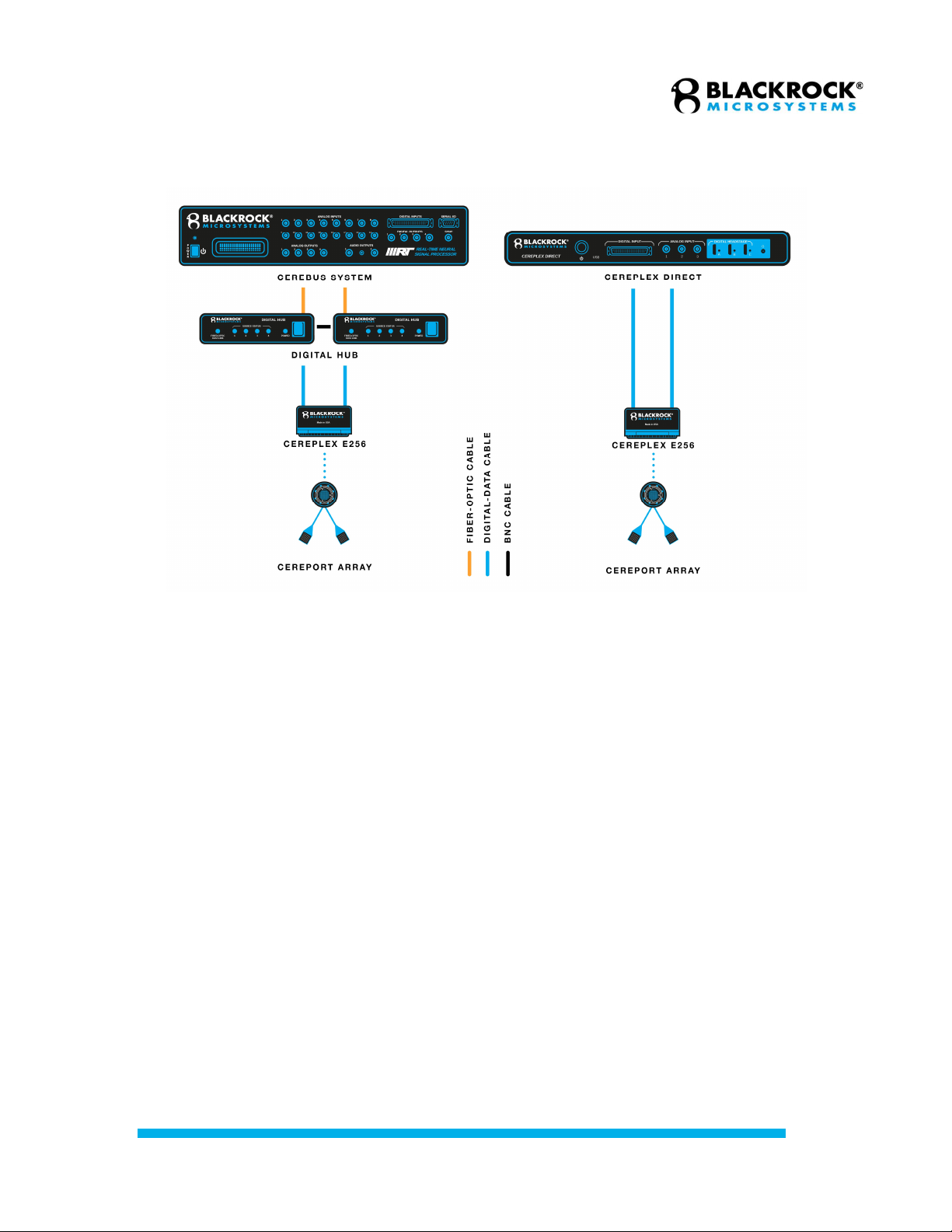
Figure 1 demonstrates how the CerePlex E96/128 connects with the Digital
Cerebus System or the CerePlex Direct in a lower channel configuration.
Figure 1–System Diagram of CerePlex E96/128 Connected to the Cerebus System or the CerePlex Direct.
Revision 4.00 / LB-0545 – CerePlex E IFU
© 2020 Blackrock Microsystems, LLC
8
Figure 2 demonstrates how the CerePlex E 256 connects with a 256-channel
Digital Cerebus System or the CerePlex Direct in a 256-channel configuration.
Figure 2–System diagram of CerePlex E256 connected to the Cerebus System or the CerePlex Direct.

Revision 4.00 / LB-0545 – CerePlex E IFU
© 2020 Blackrock Microsystems, LLC
9
Instructions for Assembly
Note: In order to use the CerePlex E 256 with a Cerebus system, two modified
Digital Hubs will be needed. If you are unsure if you have the necessary modified
equipment, contact Blackrock Support by emailing support@blackrockmicro.com.
The CerePlex E is designed to mate with the CerePort pedestal attached to
Blackrock or third-party electrodes. The CerePlex E is equipped with three guide
posts. These guide posts must be aligned with the three available notches
around the edge of the CerePort pedestal to facilitate a correct connection
between the CerePlex E and the implanted electrodes. For a detailed procedure
on how to connect the CerePlex E headstage to CerePort pedestal please refer
to the following instructions:
1. Connect the CerePlex E to either a CerePlex Direct or Digital Hub
through an HDMI A-D cable (see Figure 3).
For the E 256, HDMI Connector A is associated with banks A, B, C, and
D of the LGA connector and HDMI Connector B is associated with banks
E, F, G, and H of the LGA connector. To maintain proper channel
numbering on an E 256, the HDMI A-D cable going to HDMI Connector A
should be plugged into a lower numbered HDMI port on the Direct or Hub
than the HDMI A-D cable going to HDMI Connector B.
2. Power on the connected host device.
3. The LED on the CerePlex E should light up as blue.
Figure
3
–
HDMI connection to the CerePlex E (E96/128 shown)
Revision 4.00 / LB-0545 – CerePlex E IFU
© 2020 Blackrock Microsystems, LLC
10
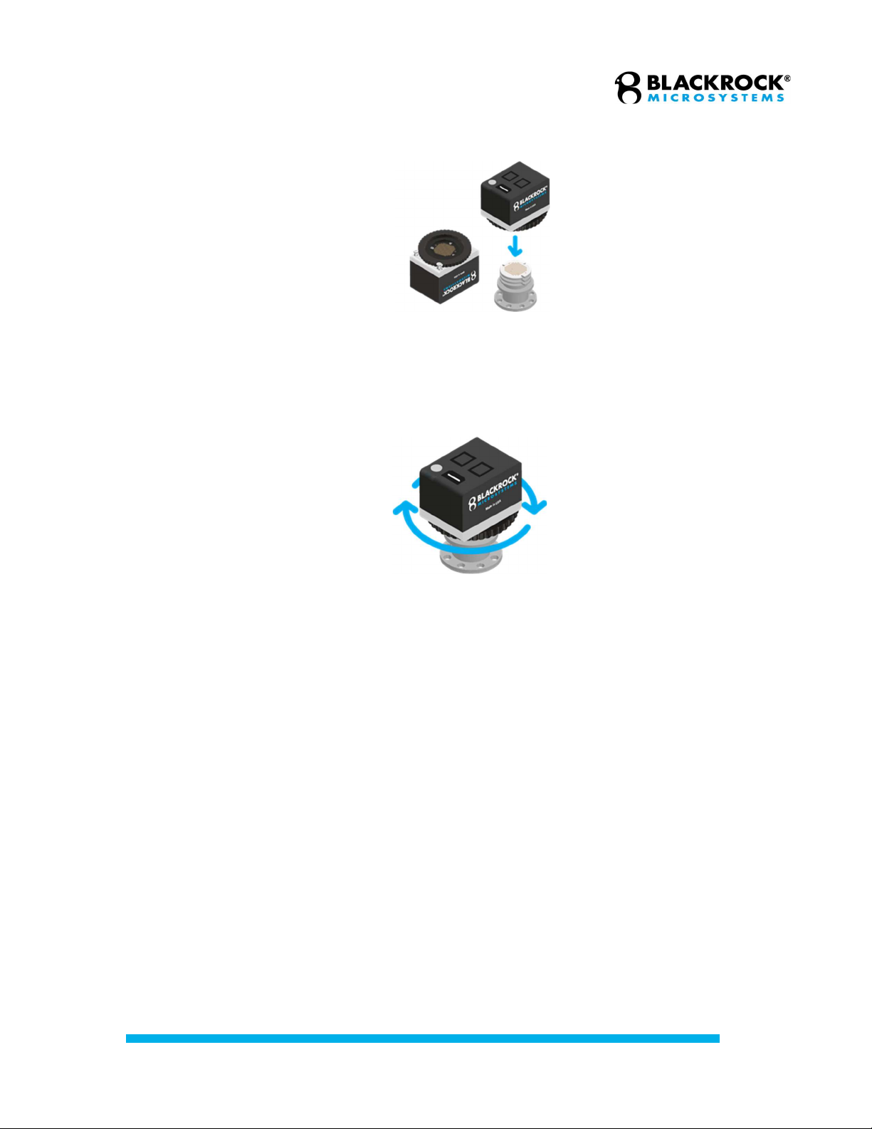
4. Roughly align the guide pins with the pedestal before attaching to the
pedestal (see Figure 4).
5. Hold the CerePlex E housing with one hand and gently rotate the wheel
clockwise with another hand (see Figure 5).
6. While screwing down, slightly rotate the housing left or right until you feel
the guide posts slide into the notches.
7. Once the CerePlex E is aligned with the pedestal, rotate the wheel
clockwise until the device is secured to the pedestal (see Figure 5).
Precaution: Avoid overtightening the CerePlex E when attaching to the
CerePort Electrode. Device damage may result.
8. The blue LED will turn green when the device is firmly mated with the
CerePort Electrode and data should be visible in the Central software.
The instructions above are also detailed in one of the Blackrock training videos which
can be accessed online from the Blackrock Microsystems website under How-to Videos.
Figure 4–Proper orientation of the CerePlex E relative to the CerePort Pedestal. Note
how the notches in the Pedestal align with the guide pins in the CerePlex E when
oriented correctly before mating
Figure 5–Rotate the wheel clockwise to secure the CerePlex E to the CerePort Pedestal

Revision 4.00 / LB-0545 – CerePlex E IFU
© 2020 Blackrock Microsystems, LLC
11
CerePlex E Channel Mapping
The high channel density of the CerePort pedestal can cause some channels to
have crosstalk or difficulty mating with the CerePlex E. You can refer to the
mapfile delivered with your Blackrock-manufactured implant assembly to the
mapping of LGA and Central channels, as well as complete electrode mapping to
Central channels. If this file is not available to you, contact Blackrock Support by
emailing support@blackrockmicro.com.
Description of Switches on the CerePlex
Impedance and Recording Selector Switch
When the selector is positioned on “Imp” the CerePlex E enters
impedance measurement mode. This mode enables users to measure
impedance of electrodes via Blackrock’s Central Suite. For information
regarding impedance measurement, please refer to the document titled
“LB 0574 Central IFU,” which is available for download from the Blackrock
Microsystems website. To revert the CerePlex E headstage into the
recording mode, simply toggle the switch to “Rec” position (recording).
Frequency Range Selector Wide & Norm
This switch toggles between two different hardware-based filter input
settings. The “Wide” filter setting corresponds to an input frequency range
from 0.02 Hz to 10 kHz. “Norm” (Normal) filter setting is between 0.3 Hz
to 7.5 kHz.
Reference and Ground Selector
This switch allows the user to select between different sources to use as
the input reference. If the switch is toggled to “Gnd” mode, subject ground
will be used as the input reference to the amplifier. Setting the switch
position on “Ref” (Reference), will use one of the implanted reference
wires (R1 or R2) as input reference. R1 and R2 can be selected by
another switch adjacent to reference and ground selector (see below).
Figure 6–Image showing all switches on the CerePlex E96/128 (left) and on the E256 (right)

Revision 4.00 / LB-0545 – CerePlex E IFU
© 2020 Blackrock Microsystems, LLC
12
R1 and R2 Reference Selector
Use this switch to select which of the two available reference wires to use
as the input reference. This selection is only relevant when the Reference
and Ground selector switch is in the “Ref” position. A switch position to
R1 selects reference wire number 1 as the input reference. The R2 switch
selects the reference wire number 2 as shown in Figure 5. The Ref/Gnd
switch must be in Ref mode for this switch to be effective. For the
CerePlex E 256, the switches closest to HDMI Connector A affect Banks
A-D (Channel 1-128) and the switches closest to HDMI Connector B
affect Banks E-H (Channel 129-256). Depending on how reference wires
are connected to the 256-ch CerePort pedestal that is mated with the
CerePlex E 256, selecting R1 or R2 for both switches may result in
different references being used for channels 1-128 and 129-256.

Revision 4.00 / LB-0545 – CerePlex E IFU
© 2020 Blackrock Microsystems, LLC
13
Cleaning & Maintenance Instructions
Sterilization
While not generally required, the device may be sterilized by both Vaporized
Hydrogen Peroxide and Ethylene Oxide Gas. Note that Vaporized Hydrogen
Peroxide may significantly discolor the case of the device. Newer models (PNs
10510, 10511, and 10757) have a new case that should not discolor.
Cleaning and Maintenance
The CerePlex E case may be wiped down with standard hospital-grade sanitizing
wipes, isopropyl alcohol (70%), ethanol (96%) or CaviWipes. If necessary, the
surfaces and connection ports may be wiped with enzymatic detergent. Dust and
debris on the exterior connectors/ports may be removed with compressed air.
The collar assembly underneath the CerePlex E should be inspected before each
use and cleaned every time after use. To clean the collar and filament film, follow
the instructions below:
1. Visually inspect the connector; remove any particles if present.
2. Visually inspect the film. If the film is swollen or degraded, follow the
section titled “Filament Film Replacement” (see below) to replace the film.
3. If necessary, clean the connector with a cotton swab and 70% isopropyl
alcohol. Do not let the cleaning solution pool. Allow the solution to dry
before use.
4. The connector and the film must also be cleaned after use with a cotton
swab and 70% isopropyl alcohol. Do not allow the solution to pool. Allow
the solution to dry before storage.
Filament Film Disassembly and
Replacement
The filament film which is visible from under the CerePlex E (See , bottom panel)
provides a conductive and uniform medium in between the input pins of the
CerePlex E and the connectors on top of the CerePort pedestal. The filament film
is conductive in the vertical direction with respect to the film surface, connecting
the contacts on the CerePlex E input and the pins on the CerePort pedestal
connector, while being insulative horizontally, eliminating cross talk. After
repeated usage, dust or biological matter can accumulate on the filament film
which can affect the signal quality on the CerePlex E.
It is recommended to regularly check the condition of the filament film before use
and replace it at least once a year or whenever there is a degradation in signal
quality. Follow the procedures below to replace the filament film.

Revision 4.00 / LB-0545 – CerePlex E IFU
© 2020 Blackrock Microsystems, LLC
14
1. Loosen the four screws on the CerePlex E by turning them
counterclockwise with a flathead screwdriver.
2. Hold the bottom three plates together and lift them away from the cover.
3. Remove the old filament film and clean the nearby area on the plate and
the PCB with cotton swab and 70% isopropyl alcohol.
4. Place a new filament film onto the plate. Make sure the holes on the film
are aligned with the pins on the plate. You may use a pair of flat-mating or
rubber-tipped tweezers to manipulate the film.
5. Replace the assembly.
6. Hold the three plates together as you lower them onto the CerePlex E
body.
7. Fasten the four corner screws clockwise.
8. Visually inspect the film placement and cleanliness. Confirm that the four
corner screws are fastened securely.
Disposal
The CerePlex E may have incidental contact with bodily fluids. Follow institutional
procedures for disposing potentially infectious or biohazardous devices when
disposing of the CerePlex E.

Revision 4.00 / LB-0545 – CerePlex E IFU
© 2020 Blackrock Microsystems, LLC
15
Magnetic Resonance
The CerePlex E has not been evaluated for safety and compatibility in the MR
environment. The CerePlex E has not been tested for heating, migration, or image
artifact in the MR environment.
Troubleshooting
Some common error states and their respective resolutions are listed below. For further
information please contact Blackrock Support at support@blackrockmicro.com.
Problem Symptom Failure Potential fix
Non-green
indicator light
on CerePlex E
Blue light will not
turn green after
mating with
pedestal
Bad mating
technique
Lack of power
Only 1 or 2
HMDI cables
connected
Make sure Hub or Direct is
powered on
Apply more force to wheel of E
to tighten the E-pedestal mate
Verify guide pins are aligned
with notches on pedestal
Verify the filament film is clean
and free of debris
For E256, make sure both
HDMI cables are connected
Poor signal to
noise ratio or
signal quality
No spikes appear
High-passed
noise band is
greater than ± 30
µv
Bad reference
configuration
Poor contact
between E and
pedestal
Incorrect
recording band
is being used
Poor
patient/subject
grounding
Excessive
noise in
operating
environment
Use of
unsynced
Digital Hubs
Try using different references,
or using ground as reference,
by toggling the E’s reference
switches (see Figure 6)
Apply more force to wheel of E
to tighten the E-pedestal mate
Add ground connections from
the patient/subject to the
Patient Ground connection on
the Direct/Digital Hub
Turn off unnecessary lab
equipment
If you are using and E256 with
Digital Hubs, make sure the
Hubs are synced by
contacting Blackrock Support

Revision 4.00 / LB-0545 – CerePlex E IFU
© 2020 Blackrock Microsystems, LLC
16
Problem Symptom Failure Potential fix
Non-green light
on Direct/Digital
Hub
HDMI indicator
lights on
Direct/Digital Hub
are either dark,
red, or orange
Incompatible
Direct/Digital
Hub
Bad cables
Bad
Direct/Digital
Hub HDMI port
Try another Blackrock-
supplied HDMI cable
Try plugging in the HDMI
cable into a different
Direct/Digital Hub HDMI port
Contact Blackrock Support for
compatibility check
Return Merchandise Authorization
In the unlikely event that your device needs to be returned to Blackrock for repair or
maintenance, do not send any equipment back without a Return Merchandise
Authorization Number (RMA). An RMA number will be issued to you by a Blackrock
representative. If you need to obtain an RMA number, you may contact a product
support representative at +1 (801) 582 5533 or by emailing
support@blackrockmicro.com.
Once an RMA number has been issued, it is important to safely pack the returned item
for shipping back to Blackrock. It is preferred that you save the original boxes and
packing materials that your system arrived in for return shipment. Please address the
package as follows:
Blackrock Microsystems, LLC
ATTN: RMA#
630 S. Komas Dr., Suite 200
Salt Lake City, UT 84108 USA
Tel: +1 (801) 582-5533

Revision 4.00 / LB-0545 – CerePlex E IFU
© 2020 Blackrock Microsystems, LLC
17
Warranty
Blackrock Microsystems (“Blackrock”) warrants that its products are free from defects in
materials and manufacturing for a period of one year from the date of shipment. At its
option, Blackrock will repair or replace any product that does not comply with this
warranty. This warranty is voided by: (1) any modification or attempted modification to
the product performed by anyone other than an authorized Blackrock employee; (2) any
abuse, negligent handling or misapplication of the product; or (3) any sale or other
transfer of the product by the original purchaser.
Except for the warranty set forth in the preceding paragraph, Blackrock provides no
warranties of any kind, either express or implied, by fact or law, and hereby disclaims all
other warranties, including without limitation the implied warranties of merchantability,
fitness for a particular purpose, and non-infringement of third-party patent or other
intellectual property rights.
Blackrock shall not be liable for special, indirect, incidental, punitive, exemplary or
consequential damages (including without limitation, damages resulting from loss of use,
loss of profits, interruption or loss of business or other economic loss) arising out of non-
compliance with any warranty. Blackrock’s entire liability shall be limited to providing the
remedy set forth in the previous paragraph.
Support
Blackrock prides itself in its customer support. For additional information on this product
or any of our products, you can contact our Support team through the contact
information below:
Manuals, Software Downloads, and Application Notes
www.blackrockmicro.com/technical-support
Complaints
When filing a complaint, please provide the product description, product number,
software version, lot number, complainant's name and address, and the nature of
the complaint.
Issues or Questions
www.blackrockmicro.com/technical-support
support@blackrockmicro.com
U.S.: +1 (801) 582-5533
The CerePlex E is not intended for use on human subjects.
Other manuals for CerePlex E Series
1
This manual suits for next models
8
Table of contents
Other Blackrock Microsystems Media Converter manuals

Popular Media Converter manuals by other brands


Intellisystem
Intellisystem IT-SDS-3016-T-16D Series user manual

Anthem
Anthem MDX-8 operating manual

Space Television
Space Television SDI-HDM user manual

Absolute Process Instruments
Absolute Process Instruments DuoPak APD 2000 Series quick start guide

Honeywell
Honeywell SiX Series installation guide

Colorado Video
Colorado Video 641 series instruction manual


