Cimarron C25 User manual

C25
APCO P25 DISPATCH DISPLAY AND COMPUTER
DATA INTERFACE UNIT
Service and Installation Manual
Manual Revision 100702
© 2010 Cimarron Technologies Corp., Escondido, CA, USA.
All rights reserved. No part of this manual may be reproduced in any way without the express written permission of Cimarron
Technologies Corporation.


C25 APCO P25 Dispatch Display and Computer Data Interface Manual
© 2010 Cimarron Technologies Corporation
All rights reserved
Cimarron Technologies Inc.
934 S. Andreasen Drive
Suite G
Escondido, CA 92029 USA
Voice : 760-738-3282
FAX : 760-480-0233
Web : www.cimtechcorp.com
Cimarron Technologies Corporation is a licensee of the Motorola MDC-1200 Protocol technology
as well as the Kenwood FleetSync Protocol.
MDC-1200 is a registered trademark of Motorola Inc.
FleetSync is a trademark of Kenwood Corporation
Not all described features are included with all systems. Contact Cimarron Technologies for
instant access to particular features.
Manual revision C25 100702

ii
Contents
C H A P T E R 1 FEATURES ..........................................................6
What Is the C25...........................................................................................................................6
Capabilities ..................................................................................................................................6
Specifications ...............................................................................................................................9
Data Formats .................................................................................................... 9
Modulation Type .............................................................................................. 9
Display Memory............................................................................................... 9
Display Type .................................................................................................... 9
Data Input......................................................................................................... 9
Interface............................................................................................................ 9
Dimensions..................................................................................................... 10
Power Requirements ...................................................................................... 10
Sounder........................................................................................................... 10
Enhancements............................................................................................................................10
C H A P T E R 2 INSTALLATION.................................................12
Jumper Information..................................................................................................................12
Radio Connections.....................................................................................................................14
Data Output .................................................................................................... 15
Channel Busy ................................................................................................. 16
Channel Acquired........................................................................................... 17
Not used in the C25........................................................................................ 17
PTT Input ....................................................................................................... 17
Transmit Control ............................................................................................ 17
Key Output ..................................................................................................... 17
OUT1, OUT2 ................................................................................................. 17
Data Input....................................................................................................... 18
RX Mute Output............................................................................................. 19
Remote Clear.................................................................................................. 20
RX Inhibit....................................................................................................... 20
Aux In............................................................................................................. 20
Ground............................................................................................................ 20
Inverting P25 Data ....................................................................................................................21
RS-232 Port................................................................................................................................21
Serial Input as a data source ....................................................................................................21
Daisy Chaining multiple C25’s in a MCC ...............................................................................22

iii
Interfacing to a Computer or Printer......................................................................................22
USB Port (Factory use only).....................................................................................................22
Resource Mapping.....................................................................................................................22
Outputs ........................................................................................................... 22
Inputs.............................................................................................................. 22
Resource Status .............................................................................................. 23
Translator Decode Installations...............................................................................................23
C H A P T E R 3 PROGRAMMING ............................................26
Programming.............................................................................................................................26
Building the Alias Table............................................................................................................27
Programming the C25 Personality...........................................................................................29
Designating Multiple Signaling Formats.................................................................................30
Setting the Date and Time ........................................................................................................31
Editing the Message Table........................................................................................................31
Access the NAC or TGID Tables .............................................................................................33
Enable "AUTHORIZE" Mode ................................................................................................34
NAC Permission Mode..............................................................................................................34
TGID Permission Mode............................................................................................................34
Programming New Flash ..........................................................................................................34
Using the $$FORMAT Command ...........................................................................................35
Radio Interface Parameters......................................................................................................38
C H A P T E R 4 OPERATION.....................................................40
Decoding Capabilities................................................................................................................40
Front Panel Displays and Controls..........................................................................................40
C25 I............................................................................................................... 40
C25 II.............................................................................................................. 41
C25 III ............................................................................................................ 42
Alarms and Alerts, Critical Message Designation..................................................................43
Alarms ............................................................................................................ 43
Alerts .............................................................................................................. 43

iv
Critical Message Designation......................................................................... 44
ID Sensitive Alerts ......................................................................................... 44
Targeting the C25 with Field Generated Alerts......................................................................45
Authorize Mode.........................................................................................................................45
NAC Permission Mode..............................................................................................................45
TGID Permission Mode............................................................................................................46
Decode Qualification by NAC and/or TGID...........................................................................46
Translator ..................................................................................................................................46
C H A P T E R 5 TECHNICAL INFORMATION............................48
RJ-11 Serial Communications Port .........................................................................................48
Fabricating a Programming Cable.................................................................. 48
Fabricating a Printer Cable............................................................................. 49
Fabricating a Daisy-chain cable ..................................................................... 49
USB Port Description..................................................................................... 49
Serial Output Formats..............................................................................................................50
Cimarron Standard ......................................................................................... 50
MODAT ......................................................................................................... 52
BED-31/1207 Output Format......................................................................... 52
Extended BED-31/1207 Output Format......................................................... 53
Cimarron Translated Output Format.............................................................. 54
CML Output Format....................................................................................... 54
Cimarron MultiChannel ANI Format............................................................. 55
Cimarron Standard Classic............................................................................. 57
Display ........................................................................................................... 58
APCO P25..................................................................................................................................58
Source ID (SRC) ............................................................................................ 58
Destination ID (DEST)................................................................................... 58
Talk Group (TGID) ........................................................................................ 58
Mfgr ID (MFID)............................................................................................. 59
Emergency flag (EM)..................................................................................... 60
Low speed data (LSD).................................................................................... 60
Network Access Code (NAC)........................................................................ 60
Data (DATA).................................................................................................. 60
Status Symbol (SS) ........................................................................................ 60
Trunking Sig Block (TSBK) .......................................................................... 61
FleetSync ID and Message Description................................................................................61
MDC-1200®ID and Message Description ...............................................................................61

v
MDC Repeater control messages ................................................................... 61
Dynamically definable MDC message definitions ..................................................................62
C H A P T E R 6 TROUBLESHOOTING .......................................63
Performing Self Tests................................................................................................................63
Installation Hints.......................................................................................................................64
Inverting P25 Data ....................................................................................................................64
Audio Data Input.......................................................................................................................65
Power Supply Schematic...........................................................................................................66
Line Input/Output Schematic...................................................................................................67
Radio Interface Schematic........................................................................................................68
C H A P T E R 7 PRODUCT SUPPORT .........................................69
A P P E N D I X A –DEFAULT HARDWARE AND
PERSONALITY CONDITIONS ....................................................................70
Default hardware conditions for the C25................................................................................70
Default personality conditions for the C25 I...........................................................................70
Default personality conditions for the C25 II and III.............................................................70
A P P E N D I X B –DISPATCH DISPLAY DIRECTIVES ........72
INDEX .......................................................................................................73

6 Chapter 1 Features
C H A P T E R 1
Features
What Is the C25
The C25 is a data decoder capable of decoding any of the
following formats: APCO P25, MDC-1200®, and/or
FleetSync . It is built to help fleet dispatchers/controllers to
communicate with and manage their fleets. The C25 family
consists of a C25 I (no alphanumeric display), a C25 II (Single
window alphanumeric display) and a C25 III (multiple window
alphanumeric display).
The C25 was developed to be:
Friendly with current technology
Real-Time
Interactive and Flexible
Powerful and Easy to Use
Flash programmable to allow for future features and
systems
Industrial-strength
Capabilities
The C25 family provides these capabilities:
User programmable to decode any of the following formats:
APCO P25, MDC-1200®, and FleetSync .
Dual format decode is standard. One C25 can monitor for
and decode two selected signaling formats.
Triple format decode, allowing one C25 to decode three
selected signaling formats. (Optional Feature. Contact Cimarron for pricing
details)
Capable of reacting to MDC-1200®Repeater Access, Setup
and Knockdown signaling.
Programmable to decode and display MDC-1200® statuses
and messages.
Large, highly visible main display.
Multiple window displays are available, capable of
simultaneously displaying up to six of the last received ID’s.
Alias programmable, relating ID’s to alphanumeric aliases of
up to eight characters long. (Requires the Alias Optional Feature. Contact
Cimarron for pricing details)
Extended aliasing (Assignment field) provides an additional
28 characters for each ID. (Requires the Alias Optional Feature. Contact
Cimarron for pricing details)

Chapter 1 Features 7
In MDC-1200 signaling, decodes and displays the entire
allowable HEX ID set.
Reacts to directed call alerts targeting the C25 programmed
ID.
P25 ID’s and MDC-1200 ID’s can be displayed in
Hexadecimal or Decimal format.
Serial communications ports can be daisy-chained from one
C25 channel card to the next channel card, eliminating the
need for serial port combiners and buffers.
Decodes and displays both the FleetSync fleet number
and unit ID.
Message types can be renamed to permit customized
systems.
Allows the review display of the last twenty received
messages.
Data Mute relay output provides N.O. and N.C. relay
contacts to be used to mute associated receiver during
MDC-1200 data reception.
COS qualified muting. Keeps the associated radio audio
muted until after a valid decode and remutes the audio
when signal reception ends for MDC-1200 and FleetSync.
P25 NAC and/or TGID Permission Mode flags valid users
by changing output states. Can be used to enable
repeaters and other communications equipment for those
users with permission.
Two programmable open-collector outputs can be related to
the reception of types of messages. Outputs can be used
to trigger external alarms, auto dialers, counters, etc.
Internal sounder can be programmed to create different
audible alerts depending on message type received.
"Authorize" permits the C25 to be used to allow only
authorized users access to repeater systems. (Requires the Alias
Optional Feature. Contact Cimarron for pricing details)
"Enunciate" feature allows unique tones to be sounded
when specific ID’s are received. (Requires the Alias Optional Feature.
Contact Cimarron for pricing details)
User programmable for a selection of many serial output
formats.
Unique user definable display personality and serial output

8 Chapter 1 Features
strings.
Programmable display type permits "Taxi Bid", "Scrolling",
and "Message and Assignment" presentations.
Incorporates a real time clock so all received data can be
time stamped.
P25 decode qualification by NAC and/or TGID.
External display clear connection can be attached to a
footswitch to clear the display by a dispatcher without
reaching for the decoder.
AGC conditioning reduces the need for adjustments on the
receive side.
Rack mountable

Chapter 1 Features 9
Specifications
Data Formats
APCO P25, MDC-1200®, FleetSync™
Modulation Type
APCO P25 C4FM 9600 BPS
MDC-1200®FSK 1200 BPS at 1200/1800Hz
FleetSync™ MSK 1200 BPS at 1200/1800Hz
Display Memory
Review twenty previous messages by
pressing "REVIEW" button on C25 II
and C25 III
Display Type
C25 I Ten LED’s indicating: Mute, Decode,
Transmit Busy, Key, Modulation,
System Error, Transmit I/O, Receive I/O
and Power
C25 II Eight large (0.7") 5x7 pixel LED display
matrixes capable of displaying up to
eight digit number or alphanumeric
alias. Can be user defined to meet
unique customer requirements.
C25 III Eight large (0.7") 5x7 pixel LED display
matrixes capable of displaying up to
eight digit number or alphanumeric
alias. Twenty Eight 0.3" 5x7 pixel LED
display matrixes capable of displaying
programmed message and assignment
fields or up to six of the previously
received ID’s or aliases. Can be user
defined to meet unique customer
requirements.
Data Input
Single ended 30mv to 12Vpp (singled ended input is
required for P-25 decode)
Balanced 600 :-30 to +10dBm; Hi Z: -36 to
+4dBm
Interface
Serial RS-232C, ASCII via RJ-11 connection,
programmable

10 Chapter 1 Features
Baud Rate: 1200, 2400, 4800, 9600,
19.2k
Data Bits: 7 or 8
Parity: Odd, Even or None
Handshake: None
Power: +5VDC on pin 1 jumper
controlled.
Data Mute Form C Relay, 1A, N.C., N.O. and
Armature.
Key Output Open collector transistor, sinks up to
500mA
External Alarms Two open collector transistors, sink up
to 500mA each. Software
programmable to respond to any
number of selected message types.
Dimensions
C25 I 7.87" x 6.25" x 2.5"
C25 II 7.87" x 6.25" x 2.5"
C25 III 7.87" x 6.25" x 4.75"
Power Requirements
5 VDC 5% at 2 A (12V option available at
additional cost)
Sounder
Audible 3400 Hz 80db(A) @ 2’.
Programmable
Enhancements
Cimarron’s C25 is modularized to allow you to enhance your
capabilities without returning the unit for upgrade. After
purchasing, these features can be activated over the
telephone. (Contact Cimarron for pricing details)
Optional features include:
Aliasing
The Alias feature is an extra option that allows the
user to create a table that is used by the C25 to
display an alphanumeric "Alias" instead of the actual
received numeric ID. The created Alias Table is
stored in the C25 and has a maximum of 9102
individual entries. The alias table also is used to

Chapter 1 Features 11
define unique "Enunciate" beeps and a twenty eight
character extended alias referred to as the
assignment field.
Triple format decode
The standard C25 is capable of decoding two
signaling formats at the same time. The triple format
decode feature can be added to permit decoding of
three different signaling types on the same audio
input line.
Translator
This feature translates incoming FleetSync™or
APCO P25 ANI into MDC-1200®format enabling
legacy dispatch systems to work in a mixed fleet
environment.

12 Chapter 2 Installation
C H A P T E R 2
Installation
The C25 may need to be programmed with your requirements
before it will work in your system. See Appendix A for the
personality that is programmed in the equipment as it is
shipped from the factory. Before installation, verify the type of
receive audio to which you are interfacing (must be flat
discriminator audio for P25 signaling) and adjust the C25
jumpers to match the level. The C25 permits you to match
system requirements with minimal loading. Proper grounding is
extremely important. Ensure that station ground is attached to
the C25 ground connections at P1 pin 8 or P2 pin 10.
Jumper Information
Jumper
Default
Purpose
JP-1
Out
For factory use.
JP-2
Out
Applies 5VDC to the RJ-11 serial connector to
power an external CDT.
JP-3
In
Attaches RxMute Output to the normally open
contacts of the mute relay.
JP-4
Out
Attaches RxMute Output to the normally closed
contacts of the mute relay.
JP-5
8-7 In
6-5 Out
4-3 Out
2-1 Out
Provides 0dB of gain.
Provides 12dB of gain.
Provides 24dB of gain.
Provides 36dB of gain.
JP-6
In
Applies a ground to RxMute Common.
JP-7
In
Internally references the data in common line to
ground.
JP-8
Out
Adds 6 dB of attenuation to the data in signal.
For use only in balanced systems.
JP-9
Out
Adds 12 dB of attenuation to the data in signal.
For use only in balanced systems.
JP-10
Out
Adds 18 dB of attenuation to the data in signal.
For use only in balanced systems.
JP-11
In
Adds 6 dB of attenuation to the data in signal.
For use only in unbalanced systems.
JP-12
Out
Adds 12 dB of attenuation to the data in signal.
For use only in unbalanced systems.
JP-13
Out
Adds 18db of attenuation to the data in signal.
For use only in unbalanced systems.
JP-14
Out
Internally applies a 600-ohm termination to the
data input lines. For use in balanced systems

Chapter 2 Installation 13
requiring termination.
JP-15
In
Grounds the microprocessor side of channel
busy. If channel busy is programmed for active
low and JP-15 is intact, the C25 will always
believe that the associated radio channel is
available (not-busy).
JP-16
In
Adds a pull-up resistor to the PTT input line.
JP-17
Out
For factory use.
JP-18
Out
For factory use.
JP-19
Out
Connects PTT in with KEY out.
JP-20
In
In conjunction with JP-21, selects NPN
transistor for PTT input circuit. This provides a
crossover point of 0.5VDC 0.3vdc for the
detection of PTT.
JP-21
In
In conjunction with JP-20, selects NPN
transistor for PTT input circuit. This provides a
crossover point of 0.5VDC 0.3vdc for the
detection of PTT.
JP-22
Out
In conjunction with JP-23, selects PNP transistor
for PTT input circuit. This provides a crossover
point of 2.8VDC 0.3vdc for the detection of
PTT.
JP-23
Out
In conjunction with JP-21, selects PNP transistor
for PTT input circuit. This provides a crossover
point of 2.8VDC 0.3 vdc for the detection of
PTT.
JP-24
Out
Add for 600 Ohm balanced configuration only
JP-25
In
Internally references the Data Out common line
to ground.
JP-26
Out
For future use
JP-27
Out
Add for 600 Ohm balanced configuration only
JP-28
Out
For factory use.
JP-29
Out
For factory use.
The C25 is shipped configured for a High Z ground referenced
system.
Jumpers JP-13, 12, 11, 10, 9 and 8 set up attenuation circuits.
Only one of these jumpers should be installed. JP-13, 12 and
11 are for unbalanced systems and JP-10, 9 and 8 are for
balanced systems.
The C25 runs on regulated 5 VDC. Use only
the factory supplied power block.

14 Chapter 2 Installation
Radio Connections
Conn
Signal
Use
P2-1
DATA OUT +
Signal output (high side) from the C Plus.
Jumper selectable for high impedance single
ended (to 14Vpp) or 600 ohm balanced (to
+10dBm). Relay switched, connected only
during data generation. Capacitively coupled.
P2-2
DATA OUT -
Signal output (low side) from the C Plus. In
high impedance single ended, this line is
referenced to ground. In balanced, it is signal
return. Relay switched, connected only during
data generation.
P2-3
CHBSY IN
High impedance input. Connect to a point that
changes state when radio is receiving (busy).
Used in COS qualified mute feature. To enable
this line, jumper JP-15 must be removed.
P2-4
CHAQR IN
Not used in the C25.
P2-5
PTT IN
Not used in the C25.
P2-6
TXCTL OUT
Used when in the Translator mode to inhibit
recovered receive audio so that it does not affect
the generated MDC-1200 translation.
P2-7
KEY OUT
Open collector output active during attack delay
and data generation in the Translator
configuration.
P2-8
OUT 1
Programmable to be active with received
message types. When the associated message
type is received, this open collector output
becomes active (low) for two seconds. Capable
of sinking up to 500 mA.
P2-9
OUT 2
Programmable to be active with received
message types. When the associated message
type is received, this open collector output
becomes active (low) for two seconds. Capable
of sinking up to 500 mA.
P2-10
GROUND
Ground
P3-1
DATA IN +
Signal input (high side) to the C25. AGC
conditioned. Jumper selectable for high
impedance single ended (30mV to 12Vpp), high
impedance balanced or 600 ohm balanced (-
30dBm to +10dBm).
P3-2
DATA IN -
Signal input (low side) to the C25. In high
impedance single ended, this line is referenced to
ground. In balanced, it is signal return.
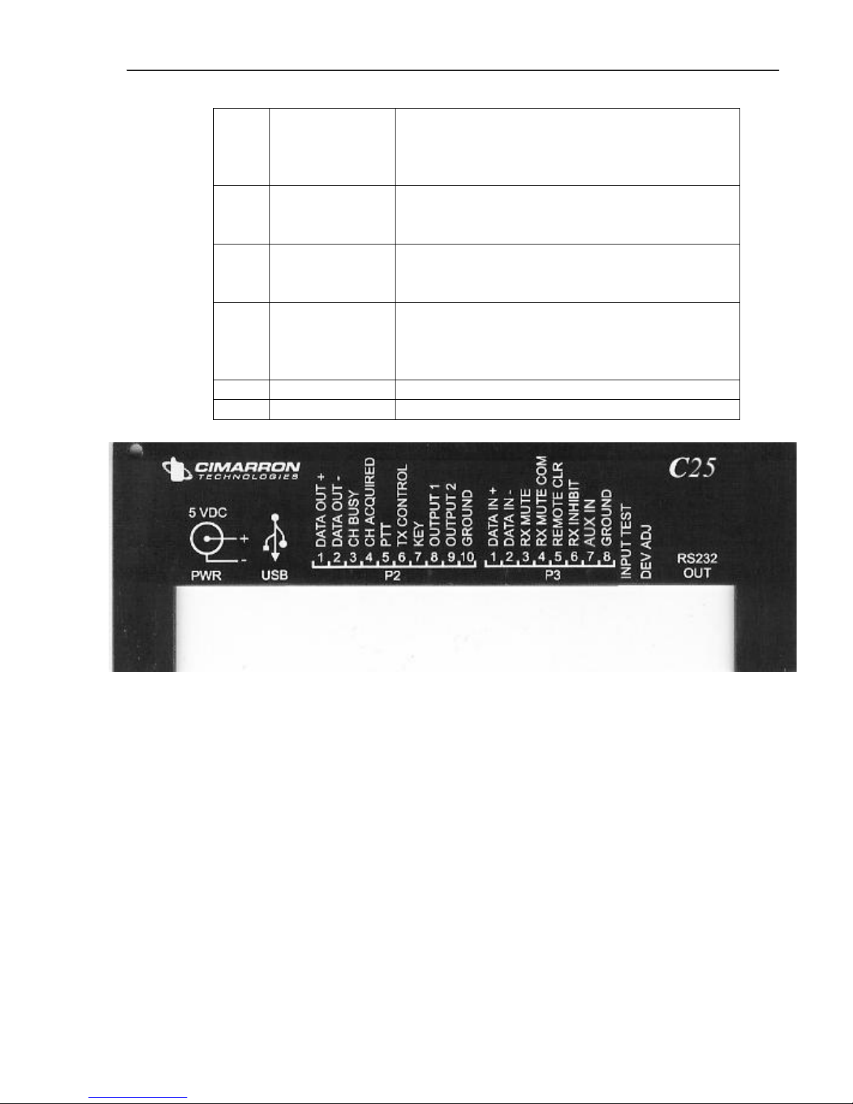
Chapter 2 Installation 15
P3-3
RXMUTE OUT
Relay output, jumper selectable for N/O or N/C
configuration. Used to momentarily interrupt
radio speaker audio to prevent the data burst
from being heard.
P3-4
RXMUTE OUT
COM
Relay output used in conjunction with RXMUTE
OUT. Jumper selectable for either "isolated
armature" or ground.
P3-5
REM CLR
Isolated input used to clear the display.
Performs the same function as the front panel
push button "Clear". Ground to activate.
P3-6
RX INHIB
Prevents decoding from taking place if signal is
active. Used in shared trunking systems to
prevent decoding of all signals present on
discriminator.
P3-7
AUX IN
Unused
P3-8
GROUND
Ground
Data Output
Data output is the signal out of the C25 when used in the
Translator configuration. Data Out + is the high side and
Data Out - is the low side. Data output is jumper
selectable for single ended or balanced configurations.
In non-balanced configurations, Data Out - is referenced
to ground. However, note that it is not directly shorted to
ground. In balanced systems, it is signal return. Always
attach an independent station ground to the rear panel
P3 pin 8 or P2 pin 10.
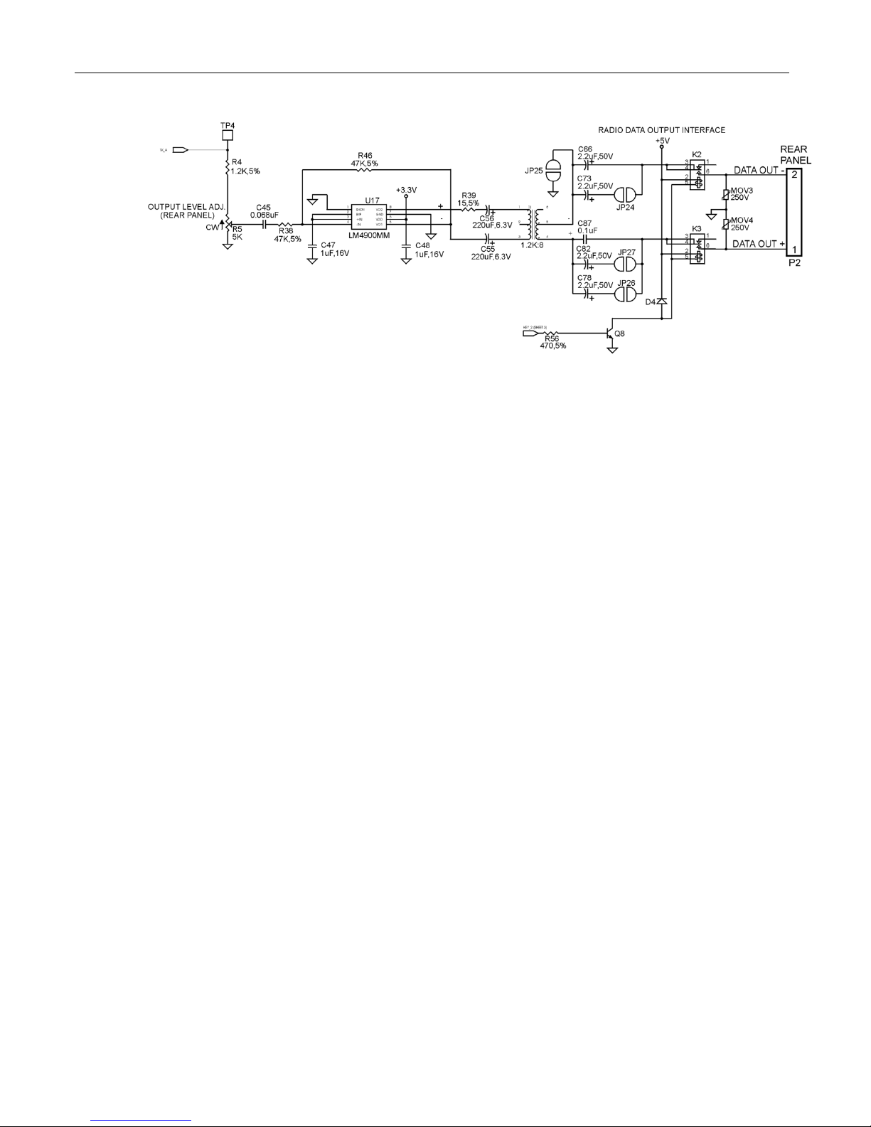
16 Chapter 2 Installation
The output is capacitively coupled for DC blocking, is
MOV protected and is completely isolated by relays
when not actively encoding.
If connected to a balanced line, remove ground jumper
JP-25. For 600 ohm operation, add jumpers JP-24 and
JP-27.
Data output must be adjusted to match the requirements
of the attached system. Rear panel potentiometer R5 is
available to adjust amplitude.
The Self-Test command $$KEYT is used for setting
outbound data level for Translator applications. This
command activates the C25 Key output and sends
MDC-1200 data for 10 seconds.
Channel Busy
Channel busy input is used to determine if the radio is in
the process of receiving (and therefore, the frequency is
occupied). Typically, channel busy would be attached to
a squelch or CTCSS circuit that changes state when
receiving. Channel Busy input sense can be
programmed to be active when high or when low.
Channel busy can be used to qualify data mute. In COS
Qualified muting, the associated radio is muted by the
C25 until a valid MDC-1200 or FleetSync data decode.
Once the data has passed, the radio is unmuted and
remains unmuted until the Channel Busy line changes
state. At that time, the radio is again muted. Note that
JP-15, which is inserted at the factory, holds channel
busy to a known state. This jumper must be removed
for the channel busy input to function.

Chapter 2 Installation 17
Channel Acquired
Not used in the C25.
PTT Input
Not used in the C25.
Transmit Control
This Line can be used when in the Translator mode to
inhibit recovered receive audio so that it does not affect
the generated MDC-1200®translation. Transmit control
function can be mapped using the $$MAP feature so
that it engages and disengages the relay typically
assigned to the mute function. This, then can be used to
break open the recovered audio path before the MDC-
1200 injection point for the duration of the MDC data.
Key Output
Key output is an open collector output that becomes
active during attack delay and data generation in the
Translator configuration.
OUT1, OUT2
OUT 1 and OUT 2 are open collector outputs capable of
sinking up to 500 mA to within 0.7v of signal ground.
These outputs are programmable to be associated with
received message types. When the associated
message type is received, the output goes low for two
seconds. This is useful for activating external alert
systems or auto-dialers. They can also be used to
remotely control devices via external relays.
If the C25 is placed in the "Authorize mode" or
NAC/TGID Permission mode from the programming
main menu, previously programmed functions of OUT1
and OUT2 are superseded and they perform as follows:
1. Open collector OUT1 becomes active goes to within
0.7v of signal ground (capable of sinking up to 500mA),
while OUT2 remains inactive, providing a high
impedance.
2. The C25 begins monitoring channel busy for activity.
3. If activity is detected on channel busy, the C25 listens
for ANI.
4. If ANI data is detected, and the decoded ANI ID is
present in the ALIAS table, OUT1 and OUT2 reverse
states, bringing OUT1 to high impedance and OUT2 to
18 Chapter 2 Installation
within 0.7V of signal ground.
5. This reversal remains in effect until channel busy
becomes inactive, then OUT1 and OUT2 reverse to their
original states.
6. If no ANI data is detected or the decoded ANI ID is
not present in the ALIAS table, OUT1 and OUT2 remain
in their original states.
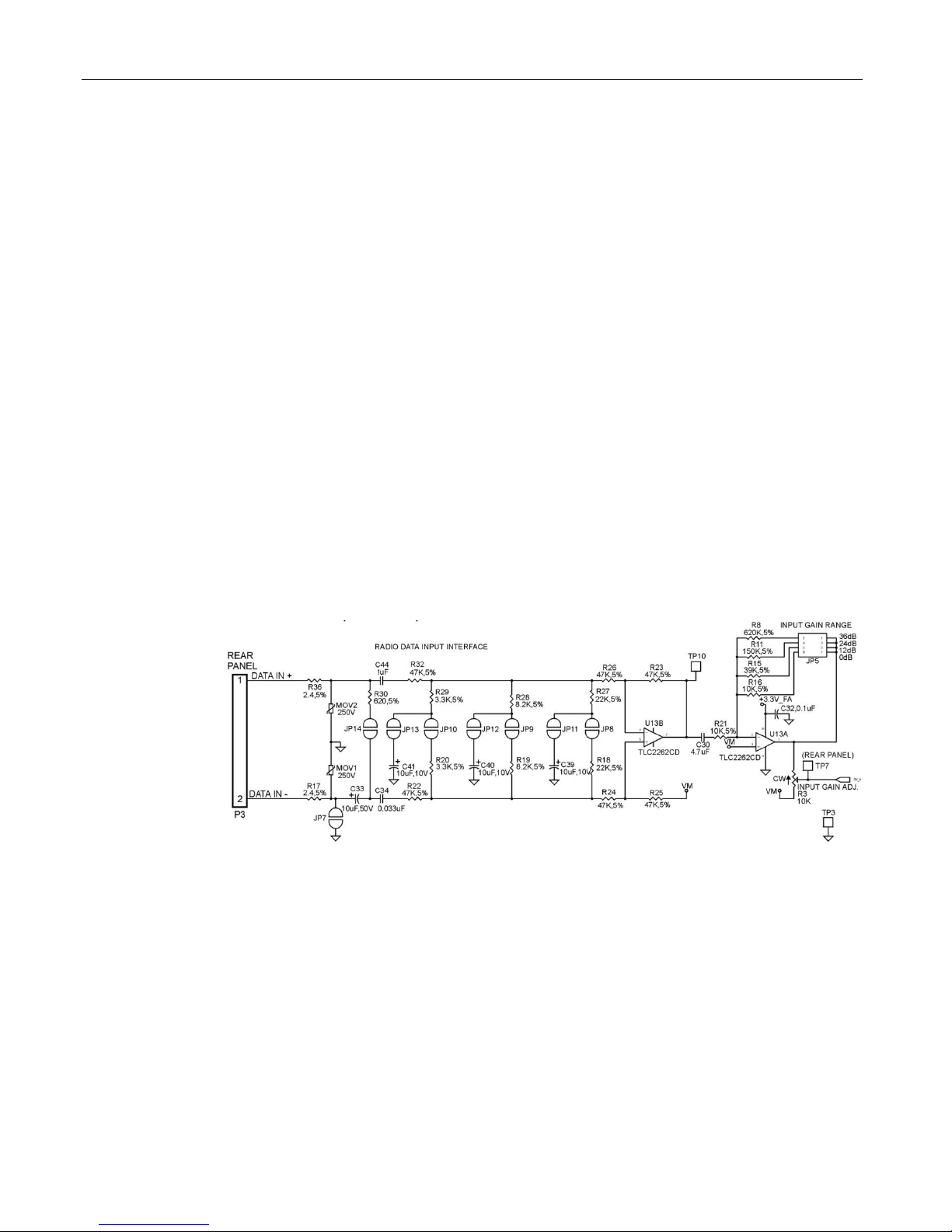
Data Input
Data input is the signal input to the C25. Data In + is the
high side and Data In - is the low side. Data input is
jumper selectable for high impedance single ended, high
impedance balanced and 600 ohm balanced. In non-
balanced configurations, Data In - is referenced to
ground. However, note that it is not directly shorted to
ground. In balanced systems, it is signal return. Always
attach an independent station ground to the rear panel
P3 pin 8 or P2 pin 10. P25 decode is not supported in
balanced line input systems. To decode P25 signaling,
the C25 input must be attached directly to the
discriminator output of the receiver and JP7 and JP11
must be installed with JP8, 9, 10, 12, 13 and 14
removed.
The input is capacitively coupled for DC blocking and is
MOV protected. When interfacing to a radio, connection
should be discriminator audio, before de-emphasis (flat
audio). Data input + should be jumpered for high
impedance and data input –should be jumpered to
ground.
APCO P25 decoding requires discriminator audio input
and does not support balanced phone line input. If not
decoding P25 data and if connected to a balanced line,
remove ground jumper JP-7 and install the 600 ohm
Table of contents
Other Cimarron Media Converter manuals

Popular Media Converter manuals by other brands

Connection Technology Systems
Connection Technology Systems HET-3012 SERIES user guide

Moxa Technologies
Moxa Technologies VPort D351 Quick installation guide

Black Box
Black Box PI125A manual

Honeywell
Honeywell TWM 9000 Supplementary instructions

ICP DAS USA
ICP DAS USA I-7530 user manual

Gomax
Gomax MX-2000A user manual


