BLASTONE Mist Blaster Instruction manual

Mist Blaster™
www.BlastOne.com
INSTALLATION, OPERATION &
MAINTENANCE MANUAL

2
MANUAL CONTENTS
Fill in your model and serial number in the blank spaces below. These can be used for reference whenever service
or maintenance is required.
Unit Serial Number
Date Of Issue
3 Safety Warnings
5 Rules For Safe Operationa
8 Description
10 How the System Works
9 How It Works
11 System Set Up
13 Operating Procedure
15 Maintenance
16 Fault Finding
18 Diagrams
21 Spare Parts & Accessories

3
SAFETY WARNINGS
Read all recommended safe procedures before attempting to use this equipment.
WARNING
• Depressurize unit before loading media or before any maintenance is performed.
• Do not use abrasives containing silica, lead, arsenic, copper, zinc or sharp glass particles - use
of abrasives containing these elements could result in serious injury or death.
• Furnish all personnel in the work area with hearing protection and approved respiratory
equipment.
• Do not modify or alter any equipment or controls without written consent from Blast One.
• Wear suitable eye protection when lling unit. There is a possibility that some abrasive may be
blown back as the pop-up valve seats.
• Always keep ngers well clear of the working area of the pop-up valve.
• Periodically check all hoses to see that they are in good condition. Repair any valves or hoses
that show any signs of wear or leakage.
• All blast operators must use approved respiratory protective equipment.
• The interior condition of the vessel should be inspected regularly for corrosion.
• All blast hose couplings and air hose couplings are provided with holes which must be safety
pinned or wired to prevent accidental disconnections.
• Any blast equipment without remote controls must have remote controls installed before
operating. Failure to do so is a violation of safety regulations and can cause serious injury
or death to personnel in the blasting area. The use of A-BEC, Clemco or a similar bleeder
type deadman can cause unintentional start-up without warning, which can result in serious
personal injury.
• Unrestricted air ow through a compressed air hose end will result in a whipping action which
can cause severe injury or death. Always attach a ball valve to each hose "at the source of supply
or branch line". Whip check hose restraints should be installed.
• Before operating any abrasive blasting equipment, READ ALL operating and maintenance
instructions. Personal protective equipment is REQUIRED when using this type of equipment.
Blasters MUST be equipped with heavy canvas or leather gloves, and blast overalls. Safety
shoes and hearing protection MUST be worn when required.
• Many coatings contain lead and other heavy metals that are toxic to humans and other life
forms. It is imperative when removing lead based coatings, that the operator be aware of the
standard industrial hygiene program as referenced in Australian Standard 4361.1. A thorough
understanding of all applicable regulations are necessary before operating this equipment.

4
SAFETY WARNINGS
When the unit is operating:
• DO NOT attempt to perform maintenance while the unit is under pressure or is even
capable of being pressurized. This means, at a minimum, the inlet valve should be closed
and ideally the air source be shut off or disconnected. Anytime the manual blow-down
valve (if tted) is closed it should be assumed the unit is under pressure.
• DO NOT aim the blast nozzle at any person or object indiscriminately;
• DO NOT remove, repair, or replace any parts while equipment is operating;
• DO NOT use worn or inferior quality hoses;
• DO NOT OVERFILL THE UNIT;
• DO NOT operate this machine without thorough knowledge of the machines’ operation;
• DO NOT exceed the recommended air pressure;
• DO NOT operate without safety locking clips and whip checks on the air hoses.
WARNING
The products described and illustrated in this manual are intended for experienced and
knowledgeable users of similar equipment used in the blasting industry. The important
safety instructions appearing in this manual cover normal conditions and situations.
Unusual, unforeseeable use may occur and in these situations, it must be understood that
common sense, caution and care are to be followed. These factors are not built into the
machine, but are supplied by the person(s) maintaining and operating it.
No representations are made or intended as to the useful life, maintenance cycles,
efciency or performance of this product or combination of products. It is the responsibility
of the user to ensure that proper and comprehensive training of operators has been
performed and all environmental and safety precautions observed.
CAUTION
WARNING LABELS
Listed below are the warning labels & the corresponding hazards encountered with the equipment.
7031-054 7031-007A

5
RULES FOR SAFE OPERATION
• Know your equipment. Do not operate this equipment in a manner other than its intended
application. Do not operate this equipment or any other equipment without following these
“Rules For Safer Operation” and all operating procedures and instructions. Learn the
applications and limitations as well as the specic potential hazards related to this machine.
Failure to do so could result in serious injury or death.
• Receive proper training. Do not operate this equipment unless you have received operational
maintenance training. Begin by thoroughly reading and understanding this operation and
maintenance manual and all included operation.
• Protect your feet. Do not operate this equipment without wearing approved foot protection.
Observe all local, state and federal safety regulations.
• Protect your eyes. Do not operate this equipment without wearing approved safety glasses.
Observe all local, state and federal safety regulations. When lling the abrasive blaster, there is
a possibility for some abrasive to be blown back.
• Protect your lungs. Do not operate this equipment without wearing approved respiratory
protection. Breathable silica may be generated by the use of this product. Silica can cause
severe and permanent lung damage, cancer and other serious diseases. Do not breathe the
dust. Do not rely on your sight or smell to determine if dust is in the air. Silica may be in the air
without a visible dust cloud. If air monitoring equipment for silica is not provided at the worksite,
then all personnel must wear appropriate respiratory protection when using or servicing this
equipment. Breathing air supplied to respirators must be of an acceptable quality.
• Protect bystanders. All blast equipment operators and personnel entering the vicinity of the
blast operation must use respiratory protective equipment that meets regulations.
• Protect your hearing. Do not operate this equipment without wearing approved hearing
protection. Observe all local, state and federal safety regulations. Loud noise is generated by
the blast nozzle and the blowdown operation of this equipment.
• Stay alert. Do not operate this equipment when you are tired or fatigued. Use caution and
common sense while operating and/or performing maintenance on this equipment.
• Do not use drugs, alcohol or medication. Do not operate this equipment while under the
inuence of drugs, alcohol or any medication.
• Keep children & visitors away. Do not let children or visitors contact this equipment or the
connecting hoses and cords. Keep children and visitors away from the work area.
• Avoid dangerous environments. Do not expose this equipment to rain. Do not use this
equipment in wet conditions. Keep work areas well lit. when working at an elevated location,
pay attention to equipment and personnel below.
• Fire damage notice. Do not operate if the vessel has been damaged by re. If damaged, take out
of service immediately and have it inspected and/or repaired at a qualied facility.

6
RULES FOR SAFE OPERATION
• Depressurize vessel before performing maintenance. Do not remove, repair, or replace any
item on this equipment while it is pressurized. Do not attempt to perform maintenance or load
media while this equipment is pressurized or even capable of being pressurized. This means
at a minimum the inlet ball valve should be closed and ideally the air source be shut off or
disconnected. Any time the manual blowdown valve is closed it should be assumed that the
abrasive blast vessel is pressurized.
• Do not modify vessel. Do not modify or alter any abrasive blaster, blast equipment, or controls
thereof without the written consent of BlastOne. Do not weld, grind or sand the pressure vessel.
It will not be safe to operate. Non-authorized modications could lead to serious injury or death.
Non-authorized modications will void your warranty and the vessel’s pressure certication.
• Inspect vessel regularly. Do not operate if the vessel has been damaged. It is not safe. Inspect
the outside and inside of the pressure vessel regularly for corrosion and damage (i.e. dents,
gouges or bulges). If damaged, take out of service immediately and have it inspected and/or
repaired by a qualied facility.
• Check for leaks in vessel. Do not operate this equipment if there is a leak. If leaking, take out of
service immediately have it inspected and/or repaired by a qualied facility.
• Never operate over maximum working pressure. Do not operate this equipment above the
maximum allowable working pressure at the maximum operating temperature as marked on
the nameplate attached to the trailer.
• Never modify discharge. Do not connect the air discharge on this unit onto a common header
with any other unit of any description, or any other source of compressed air, without rst
making sure a check valve is used between the header and this unit. If this unit is used in
parallel with another unit of higher discharge and capacity, a safety hazard could occur in a back
ow condition.
• Always use remote controls. Do not sell, rent or operate abrasive blasters without remote
controls. Regulations require remote controls on all blast machine. All blast systems must be
equipped with automatic deadman type remote controls, either pneumatic or electric. Failure to
use remote controls can cause serious injury or death to the operator(s) or other personnel in
the blasting area.
• Check for damaged parts. Do not use this equipment with damaged components. Periodically
check all valves, hoses and ttings to see that they are in good condition. Repair any component
that shows any sign of wear or leakage.
• Always use safety pins on hose couplings. Do not use this equipment without safety pins in
place. All blast hose couplings and air hose couplings are provided with holes that must be
safety pinned to prevent accidental disconnections. Accidental hose disconnection can cause
serious injury or death.
• Always use correct replacement parts. Do not use replacement parts or accessories that
are not rated for pressures equal or higher than your abrasive blaster’s operating pressure.
Improper hoses and/or ttings used on, or connected to your abrasive blaster can rupture and
cause serious injury or death.

7
RULES FOR SAFE OPERATION
• Never aim nozzle towards any person. Do not aim the blast nozzle towards yourself or any
person. System malfunction can cause accidental start-up and result in injury to personnel.
• Never use media not intended for blast equipment. Do not use blast media containing free
silica. Silica can cause silicosis or other related respiratory damage. You must wear personal
protective equipment for all abrasive blasting operations.
• Check abrasive for foreign objects. Do not use blast media that contains trash or other foreign
objects. Trash or foreign objects can create a blockage and cause equipment malfunction.
Screen recycled media to remove trash.
• Use the provided kickstand when unit is stationary. Ensure that the kickstand is down and
locked in place using provided pin whenever the Mist Blaster™ is not being moved. The
kickstand can be locked in the up position using the same pin when the unit is to be moved.
• Stop operation immediately if any abnormality is detected. Do not operate this equipment if
any abnormalities are observed during operation. Stop operation immediately for inspection.
• Inspect pop-up valve assembly. Inspect the assembly and all other associated parts for proper
working condition.
• Maintain warning labels. Do not remove, cover, obstruct, deface or paint over any warnings,
cautions or instructional material attached. Warning labels (decals) must be provided,
maintained and conspicuously located with enough light for legibility.
• Save this operation and maintenance manual. Refer to this operation and maintenance manual
as well as any additional information included from other manufacturers as needed. Never
permit anyone to operate this equipment without having him/her rst read this manual and
receiving proper training. Provisions should be made to have this manual readily available
to the operating and maintenance personnel. If for any reason the manual becomes lost or
illegible, have it replaced immediately. This operation and maintenance manual should be read
periodically to maintain the highest skill level; it may prevent a serious accident.
WARNING
Keep ngers away from the pop up valve.
Whenever compressed air is applied to the unit,
there is the possibility that the valve may energize.
Severe personal injury can result
8
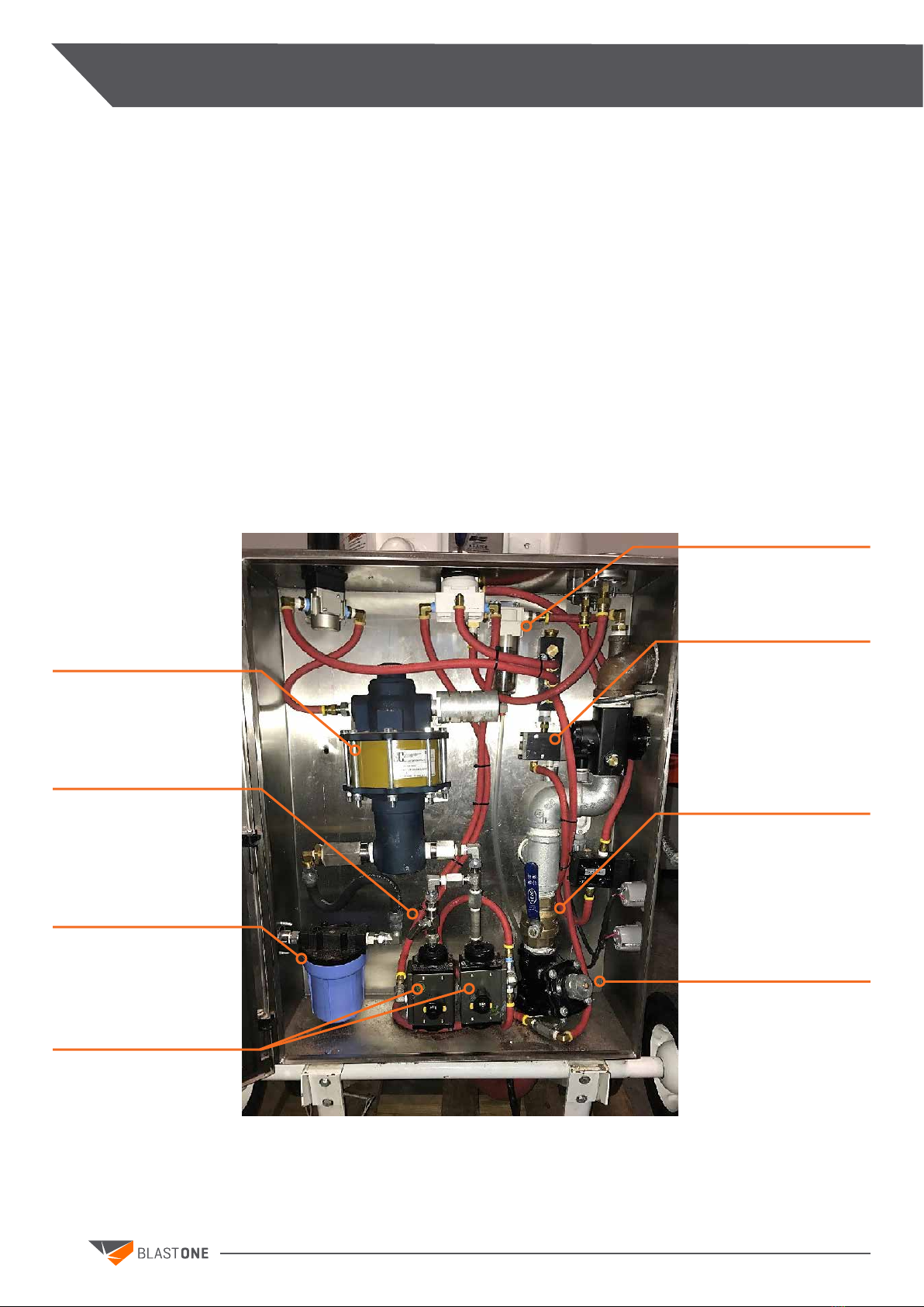
DESCRIPTION
The Mist Blaster™ is a blast machine with a cabinet mounted on a standard blast pot to allow
for mist blast, dry blast, and wash down functionality, consisting of the blast pot, an additional
mounting frame, injection block, and associated connecting hose.
The standard blast pot comprises a certied pressure vessel with internal pop-up valve, separate
electric pilot operated automatic air valve and Thompson abrasive metering valve, manually
operated exhaust valve, manually operated “choke” ball valve and associated pipe work
A three-way switch, pump regulator, blast air regulator, needle valve, and injection block are used
to allow for multifunctionality and to control each function. Both the water pressure and blast air
pressure may be adjusted using their dedicated regulators. The needle valve may be adjusted to
meter the amount of water introduced during the mist blasting.
Precautionary safety mechanisms are provided: a dead-man control and an emergency stop button.
If either the dead-man handle is released or the emergency stop is pressed, the entire system will
cease operation.
Air lter/
Moisture Separator
Deadman
control valve
Water pump
Needle valve
Water lter
Air actuated
valves
Manual
choke valve
Automatic
air valve
9
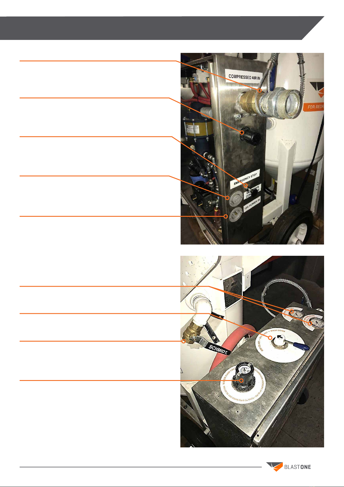
DESCRIPTION
Air inlet connection
Blast air pressure regulator
Emergency Stop Button
Deadman connection 3 pin twist lock plug
12 volt power in
Blasting pressure and supply pressure
3 way switch
Manual blow down exhaust valve
Water pump pressure regulator

10
HOW THE SYSTEM WORKS
With air supplied and with the manual exhaust (blow down) ball valve closed, the pot will be
pressurized as soon as the inlet ball valve is opened.
When the three-way switch is set to the dry blasting position, the dead-man handle is pressed, and
the emergency stop has not been actuated, the auto air valve and Thompson valve are energized.
Air pressure will then pass to the automatic air valve, which will open, allowing air to pass down
through the choke valve, through the ‘pusher’ line to the Thompson valve, and through the blast
hose to the nozzle.
When the three-way switch is set to the mist blasting position, the dead-man handle is pressed,
and the emergency stop has not been actuated, the air actuated valve corresponding to mist
blasting will open and metered water will be introduced into the system at the water injection
block. This metered water will join the abrasive from the Thompson valve and both will be propelled
through the blast hose to the nozzle.
When the three-way switch is set to wash down position, the dead-man handle is pressed, and the
emergency stop has not been actuated, the air actuated valve corresponding to wash down will
open and unmetered water will be introduced into the system at the water injection block. In this
setting, the normally open Humphrey valve is actuated which in turn deenergizes the Thompson
valve, so no abrasive is added to the stream.
When the deadman is released or the emergency stop is actuated, the entire system is de-energized,
the air, water, and abrasive supply to the blast nozzle is stopped.
The pot is still pressurized, however. To release the pressure in the blast pot, close off the inlet
ball valve, then open the blow down ball valve. When the air is released, the pop-up valve will drop,
allowing abrasive to be added if required.
Depressurization is a noisy operation, so hearing protection for operators and persons in the
vicinity is mandatory.
This control system operates on 12 volts D.C. ONLY. Do not attempt to use any other power
supply or damage will result.
FAILURE TO HEED THIS WARNING COULD RESULT IN SERIOUS PERSONAL INJURY
AND DAMAGE TO THIS EQUIPMENT
WARNING

11
SYSTEM SET UP
Connect the blasting hose to the outlet coupling
on the water injection valve. A large whip check
and safety clips MUST be used, as shown
Connect air supply hose (minimum 2” I.D.)
to the inlet connection (using a large whip
check) and connect the 12 volt power supply
and deadman cable
Connect a water supply to the water inlet

12
SYSTEM SET UP
TO FILL
The inlet air supply MUST be turned off prior to lling. Close the inlet ball valve and open the blow
down ball valve. Allow any residual air pressure to be relieved, or the pop up valve may not drop to
allow abrasive to enter.
Dump abrasive into the screen (if supplied), where it will be sieved through into the top head dish.
Pieces of the bag, etc. will be prevented from entering the pot. The abrasive will ow into the pot
until full. An excessive amount of material piled on top of the pop-up valve after the unit is full may
prevent the pop-up valve from closing properly. If the lid is moved for any reason, be sure to keep
ngers clear of the pop-up valve.
OPERATION CHECK LIST
1. The alligator clips are connected to a fully charged automotive battery.
2. The deadman cable is connected to the plug.
3. The provided kickstand is down and locked in place with provided pin.
4. The blast hose is connected to the injection connection AND has a whip check and safety locking
pin inserted.
5. Ensure adequate c.f.m. for chosen nozzle is suppled; refer to air consumption chart on page 15.
6. Ensure system is connected to a dry air supply, as moisture inside the blast pot leads to
abrasive clumping; please consult a BlastOne sales representative for a moisture control
solution.
7. The supply air hose (minimum 2” I.D.) is connected to the inlet tting AND has a whip check a
safety locking pin inserted.
8. Abrasive has been added to the pot.
9. A water supply (either tap water or gravity feed tank, not siphon) is available and turned on;
for long distances, a transfer can be used. The transfer pump should be turned off when in dry
blast mode.
10. The manual needle valve is open at least one eighth of a turn and increase/decrease as needed.
11. CLOSE the exhaust air ball valve.
12. OPEN the supply air ball valve, and allow air to enter the system. Listen for any leaks on
connections and ttings.
Failure to install safety pins on all blast hose couplings could result in serious injury or
death.
WARNING

13
OPERATING PROCEDURE
DRY BLAST
To operate in dry blast mode, turn the three-way switch to dry blast and ensure that the pump
regulator is set to 0 PSI. If using a transfer pump with a water tank, ensure that the transfer pump
is off when dry blasting. With the nozzle pointed at the work, push the deadman handle. Air and
abrasive will ow into the blast hose, and blasting will commence.
The abrasive ow can be adjusted with the control knob on the abrasive metering valve. Turn
clockwise for less abrasive and counter clockwise for more abrasive. Due to the length of the blast
hose there will be a slight delay in control of the abrasive at the nozzle, so allow a few seconds
before adjusting further.
To stop the process, release the deadman handle. Note that the pot will not depressurize; only the
blasting process will stop. The pot is still under pressure.
MIST BLAST
To operate in mist blast mode, turn the three-way switch to mist blast and ensure that the pump
regulator is set to 50 PSI. With the nozzle pointed at the work, push the deadman handle. Air and
abrasive will ow into the blast hose, and blasting will commence. Water will also be introduced,
providing dust suppression. The amount of water may be adjusted using the needle valve. Turn
clockwise for less water and counter clockwise for more water. It is not recommended to adjust the
water ow by using the pump’s air regulator, as a minimum pressure is required to inject into the
blast hose.
The abrasive ow can be adjusted with the control knob on the abrasive metering valve. Turn
clockwise for less abrasive and counter clockwise for more abrasive. Due to the length of the blast
hose there will be a slight delay in control of the abrasive at the nozzle, so allow a few seconds
before adjusting further.
To stop the process, release the deadman handle. Note that the pot will not depressurize; only the
blasting process will stop. The pot is still under pressure.
WASH DOWN
To operate in wash down mode, turn the three-way switch to wash down and ensure that the pump
regulator is set to 50 PSI. With the nozzle pointed at the work, push the deadman handle. Air and
water will ow into the blast hose, and wash down will commence.
IMPORTANT: When switching from dry or mist blast to wash down, there will still be abrasive
in the blast line for a brief period of time. Always adhere to all safety protocol when operating
the Mist Blaster™.
To stop the process, release the deadman handle. Note that the pot will not depressurize; only the
blasting process will stop. The pot is still under pressure.

14
OPERATING PROCEDURE
PROPER SHUT DOWN PROCEDURE
It is recommended that when blasting has nished, the blast hose should be ushed free of all
abrasive and water. Shut the union ball valve and set the system to dry blast and activate the
deadman. This will only take 20 to 30 seconds, depending on the length of the blast hose. When the
white haze is not observed at the nozzle, the hose is clear.
This is an important procedure, especially when working at heights. This blow through
prevents any residual water in the hose running backwards and accumulating at the Thompson
valve, resulting in a clogged valve.
DEPRESSURIZING THE POT
To release the pressure in the blast pot, close off the inlet ball valve, then open the blow down
ball valve. When all the air is released, the pop-up valve will drop, allowing abrasive to be added if
required.
WATER SUPPLY
Water supply with a positive head is required for the Mist Blaster™. You can achieve this by
positioning the uid level of the reservoir above the water inlet of the pump or by providing a
pressurized uid supply.
One way to achieve a pressurized uid supply is with a water tank and 12V transfer pump. The
transfer pump should be connected to a fully charged 12V automotive or marine battery. When
operating in dry blast mode, ensure that the transfer pump is off. In addition, ensure that the
transfer pump is off when the Mist Blaster™ is not in use. Consult a BlastOne sales representative
about suitable water supply options.
WINTERIZING THE UNIT
When operating in near-freezing to freezing temperatures, it is vital that the necessary precautions
are taken to prevent any water freezing in the pipes of the Mist Blaster™. To prevent such freezing,
run windshield wiper uid through the unit in place of water until only the windshield wiper uid
exits the unit.
Airborne particles and loud noise hazard from exhaust air can cause serious injury and loss
of hearing. Stay clear of the blow down path. DO NOT place hands or other body parts in the
blow down air path. Make sure no personnel are in the blow down air path. Wear approved
eye and ear protection.
WARNING

15
MAINTENANCE
AIR CONSUMPTION (C.F.M.) PER BLAST NOZZLE
ABRASIVE CONSUMPTION (LBS PER HOUR) PER BLAST NOZZLE
NOZZLE SIZE 60 p.s.i. 70 p.s.i. i. 80 p.s.i. 90 p.s.i. 100 psi 120 p.s.i.
No. 2 1/8” 17 19 21 24 26 30
No. 3 3/16” 37 42 47 52 57 67
No. 4 ¼” 66 75 84 93 103 119
No. 5 5/16” 103 117 131 145 158 186
No. 6 3/8” 149 169 189 209 229 269
No. 7 7/16” 203 230 258 285 312 367
No. 8 ½” 265 300 336 371 407 478
No. 10 5/8” 412 468 524 580 632 744
No. 12 ¾” 596 676 756 836 916 1076
Efciency 55% 64% 74% 86% 100% 130%
NOZZLE SIZE 60 p.s.i. 70 p.s.i. i. 80 p.s.i. 90 p.s.i. 100 psi 120 p.s.i.
No. 2 1/8” 90 105 115 130 140 165
No. 3 3/16” 205 230 260 290 320 375
No. 4 ¼” 365 420 460 500 560 660
No. 5 5/16” 575 650 725 825 900 1050
No. 6 3/8” 840 945 1050 1155 1260 1475
No. 7 7/16” 1150 1300 1450 1600 1750 2050
No. 8 ½” 1460 1660 1850 2000 2250 2650
No. 10 5/8” 2290 2600 2900 3125 3520 4100
No. 12 ¾” 3300 3750 4180 4500 5060 5950

16
FAULT FINDING
SYMPTOM POSSIBLE PROBLEM REMEDY
Air Blast but No Abrasive
(with water ow)
The pot is empty Rell
Thompson valve isolation ball valve is
closed
Open
The abrasive in the pot is wet
(Moisture can enter in vapor form
with the compressed air - this is not
uncommon depending on air quality) *
Try closing the choke valve until some
abrasive is pumped out. Operating
the unit in the "choked" condition
will allow the use of media that
is too damp to ow properly, but
it greatly accelerates wear in the
metering valve. Continuous running
in the “choked" position also reduces
productivity and therefore should be
avoided
The remote abrasive control valve is
faulty
Inspect for dirt jamming the internal
shuttle valve
Foreign matter is plugging the
abrasive metering valve
Try closing the choke valve &
opening the abrasive metering valve
momentarily to see if that will blow
the obstruction out. If this does not
work then it will be necessary to
depressurize the pot & remove the
obstruction by hand
Pop up valve/handway leak - worn or
out of alignment with seal
Check and rectify
Air control line leak Ensure all ttings are tight and there
are no holes, cuts, kinks, or abrasions
in air lines
Worn out exhaust ball valve Check and rectify
Unit turns on
accidentally
The deadman is faulty Repair or replace
Deadman control valve is faulty Repair or replace
Air Blast with
Abrasive but no
Water
Water not turned on Turn on
Needle valve closed Open
Pump pressure regulator set too low Raise to 50 p.s.i. on gauge
Air actuated valve failure Check and rectify
Needle valve blocked Remove and clean
Water lter blocked Remove and replace
Pump failure Repair or replace

17
FAULT FINDING
SYMPTOM POSSIBLE PROBLEM REMEDY
Reduced Pressure
at the Nozzle
(with or without
abrasive ow)
Undersized air compressor (see air
requirements chart)
Use a larger compressor or a smaller
nozzle
Air hose is too small The air hose diameter should be at
least 3 times the nozzle diameter.
Abrasive adjustment open too far Start off with no abrasive (fully closed)
then open slowly, whilst observing
air stream existing the nozzle, until a
slight color change can be seen
Pop-up not seating properly Check valve and “O”-ring seat
Choke valve partially closed Open fully
Nozzle is worn Inspect and replace
Unit is Slow to
Turn On or Will
Not Turn On
The control valve is faulty Inspect for dirt jamming the internal
shuttle valve
Control hoses are leaking Check and repair
Control hoses are plugged or kinked Repair as necessary
Breather vents clogged Inspect and replace

18
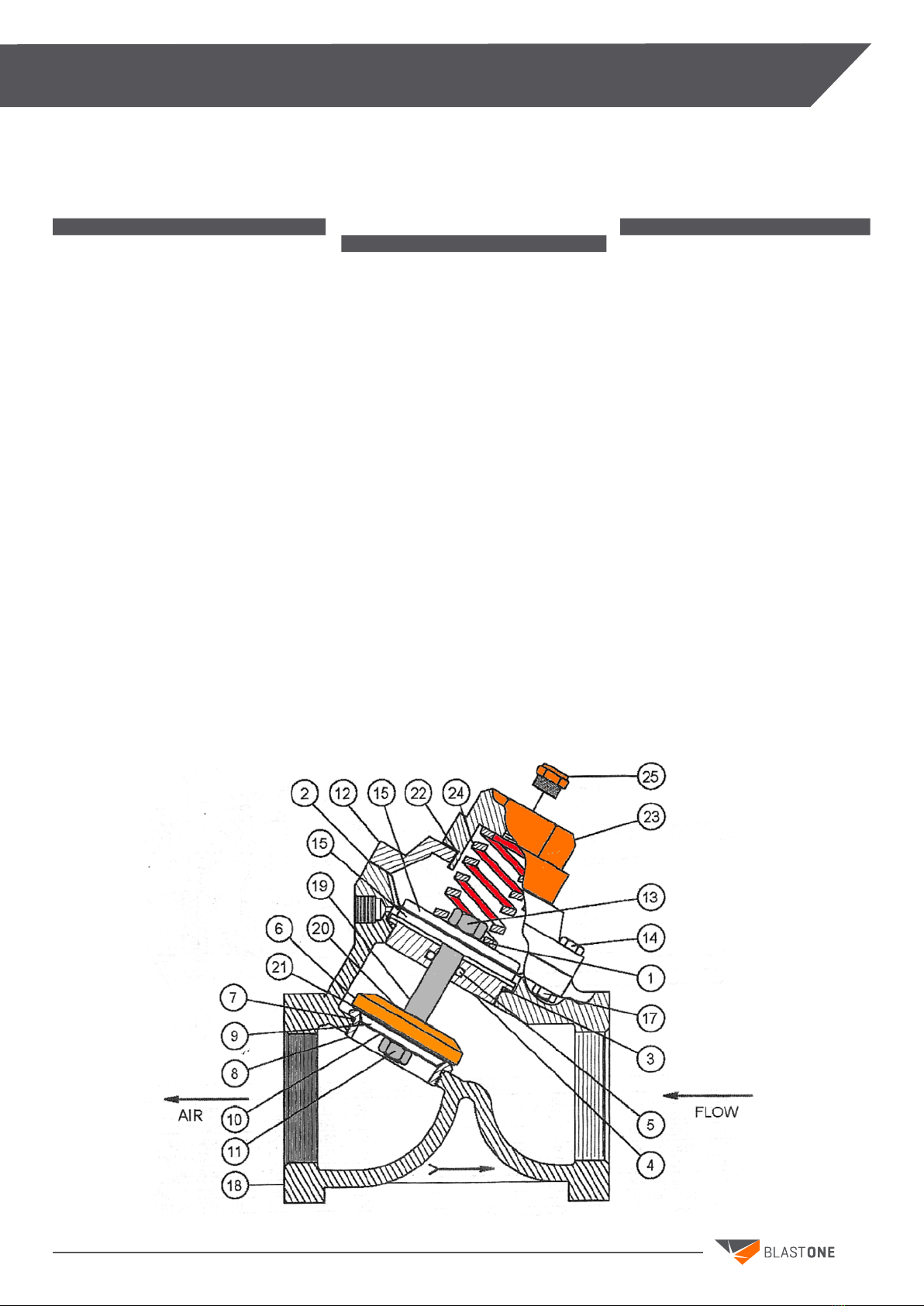
DIAGRAMS
NOTE: With spring closed valve air ow is in opposite direction from arrow on valve body.
2152-006 1" Valve With Tungsten Carbide Sleeve
2152-106 1" Valve With Urethane Sleeve
2152-007 1 1/4" Valve With Tungsten Carbide Sleeve
2152-107 1 1/4" Valve With Urethane Sleeve
2152-008 1 1/2" Valve With Tungsten Carbide Sleeve
2152-108 1 1/2" Valve With Urethan Sleeve
NO. PART NO. DESCRIPTION
2152-000-99 Repair Kit With Tungsten Carbide Sleeve
2152-100-99 Repair Kit With Urethan Sleeve
12152-000-01 Knob
22152-000-17 Breather Vent
32152-000-12 Spring Retainer
4*+ 2152-000-18 O-Ring
57027-503-02 Washer
67010-507-07 Hex Bolt, 3/8" UNC x 1-1/4" Lg.
72152-000-02 Cap Plate
8*+ 2152-000-16 Cap Gasket
92149-000-19 Bump Ring
10 2152-000-25 Vibration Disc
11 2152-000-03 Spring
12 2149-000-08 Nut
13*+ 2149-000-04 Piston Seal
14 2152-000-05 Piston
15*+ 2152-000-07 Tungsten Carbide Plunger
16 2152-000-09 Cylinder
17*+ 2149-500-06 Plunger Seal (Molythane)
18*+ 2152-000-06 Plunger Seal (Urethane)
19 2152-000-14 Body
20+ 2152-100-13 Urethane Sleeve
21 2152-000-19
2152-000-15
2152-000-11
Base, 1" NPT
Base, 1 1/4" NPT
Base, 1 1/2" NPT
22 7010-507-95 Hex Bolt, 3/8" UNC x 4 3/4" Lg.
23 3014-106 Plug
24* 2152-000-21 O-Ring
25* 2152-000-13 Tungsten Carbide Sleeve
26* 2152-000-10 Seat
27 8403-000-54 Cleanout Ball Valve Adder
28 3006-106 Street Elbow 90°, 1" Galv.
29 3029-106-09 Nipple TBE, 1" x 2" Lg. Galv.
30 2401-506 Ball Valve, 1" Full Port
* Included in Repair Kit for Tungsten Carbide Sleeve
+ Included in Repair Kit for Urethane Sleeve
THOMPSON VALVE®II
19
DIAGRAMS
AUTOMATIC AIR VALVE (NORMALLY CLOSED)
2123-106 1" Valve
NO. PART NO. DESCRIPTION
2123-006-99 Repair Kit
1* 2123-006-01 Gasket
2* 2123-006-02 Diaphragm
3* 2123-006-03 O-ring
42123-006-04 Retainer Bushing
5* 2123-006-05 O-ring
62123-006-06 Disk Retainer
7* 2123-006-07 O-ring
82123-006-08 Seat
92123-006-09 Disc Plate
10 "Deleted" Lock Washer, Internal
11* 2123-006-11 Lock Nut
12 2123-106-12 Cap
13* 2123-006-13 Hex Nut (w/Locktite)
14 2123-006-14 Cap Screw
15 2123-006-15 Diaphragm Plate
17 2123-006-17 Lock Nut
18 2123-006-18 Body, 1"
19 2123-006-19 Shaft
20* 2123-006-20 Gasket
21* 2123-006-21 Disc
22 2123-106-22 O-ring
23 2123-106-23 Spring Retainer
24 2123-106-24 Spring
25 2014-300 Vent, 1/8"
(not included)
* Included in Repair Kit
2123-109 2" valve
NO. PART NO. DESCRIPTION
2123-009-99 Repair Kit
1* 2123-009-01 Gasket
2* 2123-009-02 Diaphragm
3* 2123-009-03 O-ring
42123-009-04 Retainer Bushing
5* 2123-009-05 O-ring
62123-009-06 Disk Retainer
7* 2123-009-07 O-ring
82123-009-08 Seat
92123-009-09 Disc Plate
10 "Deleted" Lock Washer,
Internal
11* 2123-009-11 Lock Nut
12 2123-109-12 Cap
13* 2123-009-13 Hex Nut
(w/Locktite)
14 2123-009-14 Cap Screw
15 2123-009-15 Diaphragm Plate
17 2123-009-17 lock Nut
18 2123-009-18 Body, 2"
19 2123-009-19 Shaft
20* 2123-009-20 Gasket
21* 2123-009-21 Disc
22 Not Needed
23 2123-109-23 Spring Retainer
24 2123-109-24 Spring
25 2014-300 Vent, 1/8"
(not included)
* Included in Repair Kit
2123-107 1 1/4" Valve
2123-108 1 1/2" Valve
NO. PART NO. DESCRIPTION
2123-007-99 Repair Kit
1* 2123-007-01 Gasket
2* 2123-007-02 Diaphragm
3* 2123-007-03 O-ring
42123-007-04 Retainer Bushing
5* 2123-007-05 O-ring
62123-007-06 Disk Retainer
7* 2123-007-07 O-ring
82123-007-08 Seat
92123-007-09 Disc Plate
10 "Deleted" Lock Washer, Internal
11* 2123-007-11 Lock Nut
12 2123-107-12 Cap
13* 2123-007-13 Hex Nut (w/Locktite)
14 2123-007-14 Cap Screw
15 2123-007-15 Diaphragm Plate
17 2123-007-17 Lock Nut
18 2123-007-18 Body, 1 1/4"
2123-008-18 Body, 1 1/2"
19 2123-007-19 Shaft
20* 2123-007-20 Gasket
21* 2123-007-21 Disc
22 2123-107-22 O-ring
23 2123-107-23 Spring Retainer
24 2123-107-24 Spring
25 2014-300 Vent, 1/8"
(not included)
* Included in Repair Kit

20
DIAGRAMS
CONTROL VALVE
2229-100 Electric Control Valve, 12 Volt D.C.
2229-101 Electric Control Valve, 12 Volt A.C.
2229-102 Electric Control Valve, 24 Volt D.C.
NO. PART NO. DESCRIPTION
2229-100-99 Replacement Parts Kit (Electric)
1Not Available Air Operator Cap
2*+ 2229-000-02 Plunger w/O-Rings
3Not Available Valve Body
4*+ 2229-000-04 Spring
5Not Available Spring Retainer
6*+ 2229-000-06 Filter Disk
8Not available Screw (8)
92229-000-09 Air Operator Assembly
10*+ 2229-000-10 O-Ring (2 ea)
11 Not Available Electric Operator Cap
12 Not Available Coil Cover Bottom
13 2229-100-03 Coil 12 Volt D.C.
2229-101-03 Coil 12 Volt A.C.
2229-102-03 Coil 24 Volt D.C.
2229-100-03 Coil 24 Volt A.C.
14 Not Available Coil Cover
15 Not Available Nut
16 2229-100-06 Solenoid Pilot Assembly, 12 Volt D.C.
2229-101-06 Solenoid Pilot Assembly, 12 Volt A.C.
2229-102-06 Solenoid pilot Assembly, 24 Volt D.C.
17+ 2229-100-07 Gasket (Electric Only)
+ Included in Replacement Parts Kit-Electric
Table of contents
Other BLASTONE Shot Blasting Machine manuals


