Blata Origami B1 User manual

MINIBIKE – ORIGAMI B1
SERVICE MANUAL FOR USE AND MAINTENANCE AND SPARE PARTS LIST
For your own safety and the safety of others Follow these recommendations in order to use
your MINIBIKE safely and correctly. Read the instructions CAREFULLY, failure to do so may
place yourself and others in extreme and or ultimate DANGER. If you do not understand the
instructions and Data then, you are not to attempt to operate this Minibike under any
circumstances. It may be used for show purposes only!
CONTENTS
PAGE
INTRODUCTION .............................................................................................................. 2
TECHNICAL DATA .......................................................................................................... 2
UNPACKING AND SETTING UP BEFORE RIDING ....................................................... 3
SAFETY............................................................................................................................ 3
BEFORE STARTING........................................................................................................ 3
STARTING THE ENGINE - FIG. 2 ................................................................................... 4
CARBURETOR - FIG. 3 ................................................................................................... 4
RIDING ............................................................................................................................ 4
PERIODIC MAINTENANCE............................................................................................. 5
CHAIN SETTING AND MAINTENANCE ......................................................................... 5
CENTRIFUGAL CLUTCH REPAIR OR REPLACEMENT…............................................ 5
BRAKES ADJUSTING - FIG. 4........................................................................................ 6
FRONT BRAKES PADS REPLACEMENT - FIG. 7 ......................................................... 6
REAR BRAKES PADS REPLACEMENT - FIG. 7. ......................................................... 6
REMOVE AND REFIT THE FRONT WHEEL – FIG. 5 ……………................................... 7
REMOVE AND REFIT THE REAR WHEEL - FIG. 5 ................................................ ....... 7
REPLACEMENT OF SPROCKET - FIG. 9 ..................................................................... 7
MINIBIKE ORIGAMI B1 - FIG. 5 …………………………………………………....................8,9
PARTS LIST ……………………………………………………………………....................... 10,11
ENGINE - BLATA …………………………………………………………………................ 12
CLUTCH COMPLETE - FIG. 6…………………………………………………..................... 13
FRONT AND REAR BRAKES - FIG. 7 …………………………………………................. 14
REPLACEMENT OF TIRE – FIG. 5 ................................................................................. 15
REMOVE AND REFIT AIR FILTER .................................................................................. 15
CLUTCH ADJUSTMENT – FIG. 8 ………………………………………………................... 15
MAINTENANCE OF COOLING SYSTEM ………………………………………................. 16
TORQUE SETTINGS ......................................................................................................... 17
STORAGE PROCEEDURES …………………………………………………………............. 18

INTRODUCTION
The Minibike Origami B1 is designed and built for use on a paved closed circuit
track. The track should be clean and without obstacles of any kind. Qualified
adults and younger persons can drive the minibike. Children can drive the
minibike only under the supervision of a responsible adult person. The
minibike is constructed especially for racing competitions on special racing
tracks.
The minibike uses a single-cylinder two-stroke, Gasoline combustion engine,
and has an air filter and exhaust silencer. Transfer of power to the rear wheel is
through a drive chain. The the overall drive ratio to the rear wheel can be
changed by the replacement of chain sprockets. The front and rear wheel is
equipped with disk brakes. The rear brake is controlled with the left lever and
the front brake is controlled with the right lever on the handlebars.
BASIC TECHNICAL DATA
ENGINE: BLATA…………………………….………………………TWO-STROKE
NUMBER OF CYLINDERS.................................................................1
CYLINDER CAPACITY …………………………….. .........39,8 cc
ENGINE COOLING SYSTEM………………………..LIQUID COOLED
POWER OUTPUT........................................... 10,5 kW at 12 300 rpm
TORQUE ………………………………................8,1 Nm at 12 000 rpm
CARBURETOR...........................................PHVA 17,5 DELL’ ORTO
FUEL ADMISION …………REED VALVE DIRECT TO CRANKCASE
IGNITION...................................................................CONTACT-LESS
SPARK PLUG……………………..................................... NGK B9ES
STARTING...........................................HAND PULL TYPE, MANUAL
CLUTCH............................................... CENTRIFUGAL AUTOMATIC
FRAME: ENHANCED TRELLIS…………….. SUPPORTING STRUCTURES
MADE OF LIGHT ALLOYS
BRAKES: FRONT WHEEL... DISC BRAKE – DISC DIAMETER 162mm ( 6,3”)
REAR WHEEL ........DISC BRAKE-DISC DIAMETER 119 mm ( 4,7”)
WHEELS: FRONT ............................................OF LIGHT ALLOY 2,1”x 6,5”- 99
REAR ............................................OF LIGHT ALLOY 2,1”x 6,5”- 130
TIRE: FRONT ......................................................................SIZE 90/65 - 6,5”
REAR ..........................................................110/50 - 6,5”, 90/65 - 6,5”
FUEL: .........MIXTURE OF PETROL 92 OR HIGHER OCTANE +2 STROKE
SYNTHETIC OIL
MIXING RATIO (after break in period).......................................50: 1
TANK CAPACITY............................................1,7 Liter 0,44 US gal. )
UNLOADED WEIGHT: ..................................................................... 25 kg ( 55 lb. )
CARRYING CAPACITY: ...............................................................110 kg ( 242 lb. )
BASIC DIMENSIONS:
LENGTH....................................................................1 100 mm ( 41” )
WIDTH......................................................................... 560 mm ( 22 “ )
HEIGHT.....................................................................550 mm ( 21,6” )
UNPACKING AND SETTING UP BEFORE RIDING
The minibike is delivered in a cardboard carton and packed with folded
handlebars and brake levers. After unpacking, set up the handlebars into the
position, that suits the best for driving. The maximum pulled brake lever
position should not touch on the handlebar grip. After setting up, tighten the
handlebar sleeve (clip-on) nuts 1; tighten the brake lever bolts and the throttle
assembly 3. See, Fig.1. By loosening the nut M8 (P/N 920.010.01) on the foot
peg bracket, the rider can adjust the foot peg position in a forward or rear
direction. The foot rest can be moved to the front or back position. It is
recommended to try and check the position of handlebars and foot rests
individually. While tightening the bolts and nuts, do not use an excessive force
as to not damage the threads, or distort the tubes and other parts. Verify the
smooth and perfect function of the Bowden cables to throttle and both brakes.
Fill the cooling system with coolant and vent the system (follow the
instructions in chapter MAINTENANCE OF COOLER SYSTEM). Fill the fuel
tank with fuel mixture. Failure to use the proper oil mix ratio will result in
Engine damage for which you will be responsible.
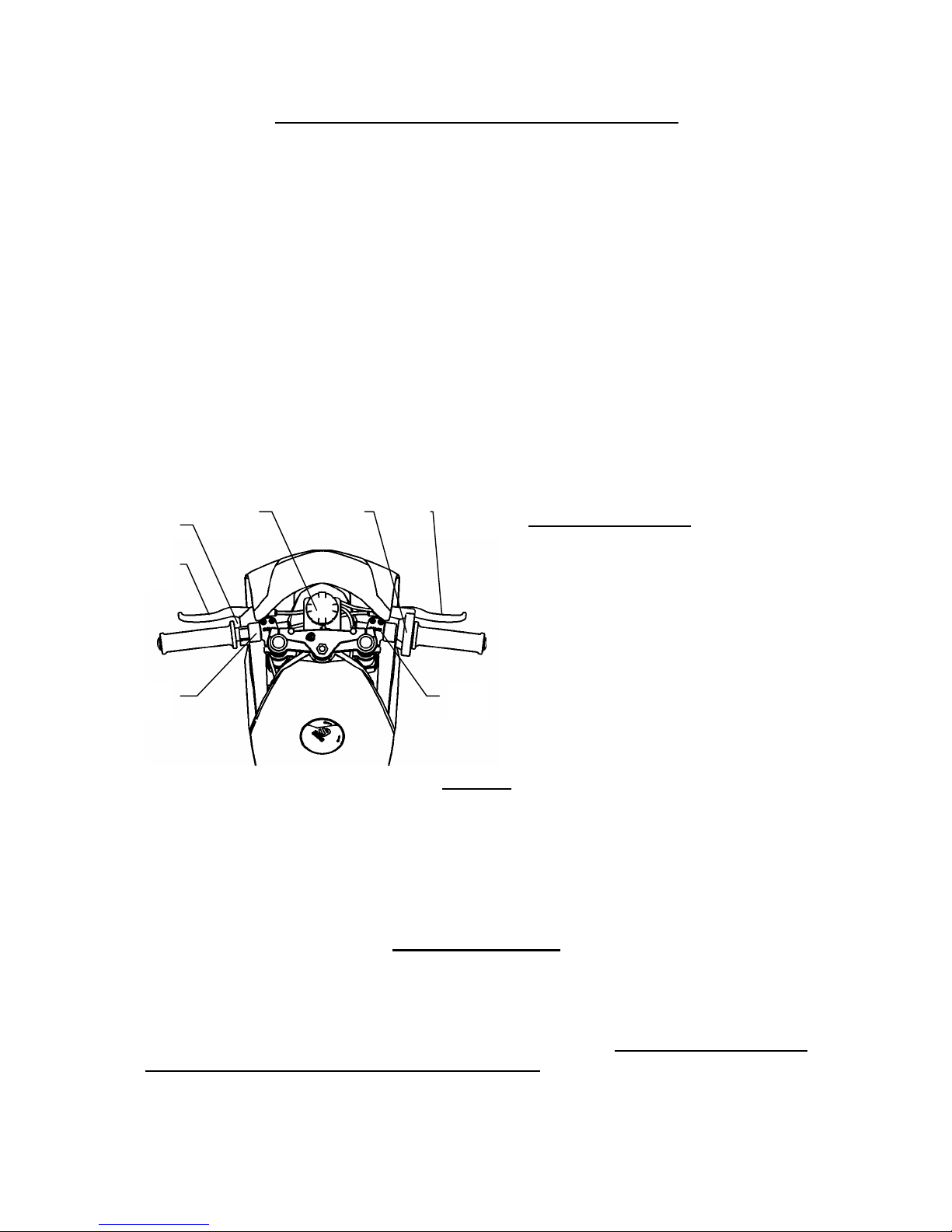
Fig. 1
Operating controls:
1. Handlebar bolts
2. Brake lever bolts
3. Throttle Assy. bolts
4. Stop switch
5. Front brake lever
6. Rear brake lever
7. Balance tank for coolant
Range of adjusting handlebars
function position
SAFETY
The minibike is unsuitable for public road use. It does not comply with valid
Safety Standards. Unsafe and careless use of a minibike can result in serious
injuries. The driver can minimize the potential risks by wearing the Safety
Equipment. The driver must wear safety helmet, goggles, gloves, elbow pads,
kneepads, and firm footwear. The minibike cannot be used on wet, icy or oily
surfaces. Avoid uneven surfaces and obstacles. Drive with two hands on the
handlebars. BEFORE STARTING
It is strongly recommended to follow all the instructions about the break-in
period to promote engine reliability and long life. Break-in period of the
minibike is complete after the consumption of five full fuel tanks. It is important
to use mixture of petrol 92 or higher Octane with 2-stroke synthetic oil in the
ratio 30:1 and after break-in period a ratio of 50:1. Mix the petrol and oil
completely before putting it into the fuel tank. During the break-in period do
not run the engine at maximum RPM and do not allow the engine to overheat.
1
6
4
2 7 3 5

Check the tire inflation – 200 kPa (2 bars) or (28 to 30psi) to be commensurate
with the driver’s weight. The Tyre pressure should never exceed 2,5 bars,
(38psi) in either the front or rear wheel.
IMPORTANT NOTICE: If the coolant level rises in the balance tank, switch off
the engine immediately! Check the drive of the coolant pump and sealing of the
cooling system. After these steps, execute the ventilation of the Radiator. The
raised level of coolant is an indicator of a overheated engine, which can result
in seizing the piston in the cylinder.
STARTING THE ENGINE
Engine starting should be done only on the stand - Fig. 2. Fill the fuel tank and
close it with the filler cap. Open the Gas petcock. Set the petrol supply cock.
Set the choke lever into position “C”, Fig. 3. Without turning the accelerating
handle, pull gently twice the starting wire and by next guick pull start the
engine. It is not allowed to pull the starting wire up to full winding off. The
choke lever will turn back to the position “A” automaticaly by turning the
accelerating lever after a short engine run . Let the engine run about 1 min.
Leave the minibike on the stand with running engine and if necessary adjust
the revolutions so the rear wheel is not turning. For adjustment use the
adjustment screw No. 3 on the carburetor Fig. 3.
Fig. 2
CARBURETOR
1. Air filter
2. Carburetor body
3. Idle speed adjusting screw
4. Float chamber
A – Cock position for riding
C – Cock position for cold starting
Fig. 3 RIDING
Remove the minibike from the stand to sit on the seat. When seated, then
slowly rotate the throttle grip to start riding. Before braking, rotate the Throttle
grip to the off or idle position and lightly depress the rear brake lever with left
hand and then the front brake lever with right hand. Beware to not skid the
wheels. The minibike engine is switched off by pushing the red button (Engine
stop switch) on the handlebars. It is necessary to check the tightness of bolts
and nuts, especially of the engine, and the brake settings after the first ride and
often during the break in period.
1 2
4
3
C
A
Other manuals for Origami B1
1
Table of contents
Other Blata Motorcycle manuals

Blata
Blata Minibike Elite 13 Junior User manual

Blata
Blata Elite 13 W User manual

Blata
Blata Origami B1 User manual

Blata
Blata Ultima User manual

Blata
Blata Elite 14 - 4 User manual

Blata
Blata ELITE 14-WRS User manual

Blata
Blata minimocard 2.6 Instruction manual

Blata
Blata MOTARD 125 BXM User manual

Blata
Blata Minibike Elite 14 WRS User manual
Popular Motorcycle manuals by other brands

MV Agusta
MV Agusta Brutale 675 Workshop manual

APRILIA
APRILIA RSV MILLE - PART 1 1999 User manual content

Royal Enfield
Royal Enfield Himalayan 2018 owner's manual

SSR Motorsports
SSR Motorsports Lazer5 owner's manual

MOTO GUZZI
MOTO GUZZI 2005 Griso 1100 Use and maintenance book

KTM
KTM 85 SX 19/16 owner's manual


