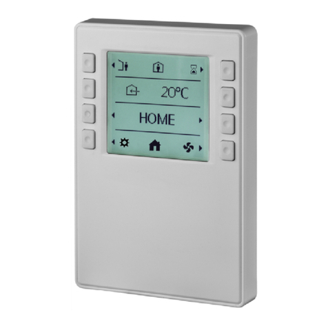
BleBox Thermobox User manual

WIRELESS SMART THERMOSTAT
control with μWiFi technology
from any place in the World
SAFETY RULES
Do not connect the device to loads exceeding the permitted
values.
Connect only in accordance with the diagram presented in the
manual. Improper connections may be dangerous, it can damage
the controller, and loss of the warranty.
DANGER! Risk of electric shock! Even with the device turned o,
the outputs may be live. All assembly work should be ALWAYS
performed with the disconnected power circuit.
The installation of the device to a power mains that does not
meet the quality requirements dened by PN-EN 50160, will
result in the loss of the warranty.
To ensure protection against electric shock, the protective
terminal of a I class devices must always be connected to the
protective earth (PE) therminal in the TN-S network or to the
neutral-protective (PEN) therminal in the TN-C network. At the
instalation of electrical devices, special attention must be paid to
the protection against electric shock described in PN-HD
60364-4-41.
Protect the power circuit with overcurrent protection in B
characteristic and rated current up to 16A.
Connection of the controller must be carried out only by persons
with the corresponding electrician license.
1INSTALLATION - BASICS
Disconnect the installation supply voltage before installing the controller.
Remember that any mounting works should be carried out when the mains
voltage is disconnected (switch o the mains fuse or disconnect the power
cord from the mains socket).
The controller should be installed in a place protected against adverse
environmental conditions, protected from third party access - in the ush box
or inside the enclosure of the controlled device. Remember that metallic
elements (wires, housing parts) have a negative inuence on the range of the
device, and consequently the comfort of use. It is recommended that the
device be mounted in a stable and xed position. Due to the operating
voltage of the device it is necessary that the connectors of the controller be
protected against accidental contacts or short circuits, which could cause
electric shock or damage to the device.
A digital probe was used to measure the temperature, which should be
placed inside the heated / cooled room according to the recommendations in
the diagrams. The nal decision on the choice of probe location is made by
the installer. It is not recommended to extend the original temperature probe
cable excessively since the induced interference can cause the controller
malfunction or even damage it.
The controller is designed to work with an additional safety sensor whose
task is to limit the heating of the surface contiguous to the heaters (e.g.
wooden oor) during heating or freezing (e.g. evaporator) during cooling.
The maximum (minimum) safe temperature is selected in the controller
settings during conguration. The controller will regulate heating / cooling
so as not to exceed the safe surface temperature (measured with the safety
probe) while reaching the set temperature. The main probe provides readout
of the current room temperature for regulation.
After making sure that the device is connected in accordance with the
diagram and that there are no metal components near the controllerwhich
may accidentally cause short-circuit, start the device by turning on the power
(turning on the mains fuse or connecting the power cord to the power
outlet).
Read the diagram and then proceed to install the controller. Pay particular
attention to the designation of the controller connectors. Start with power
wires - phase L (usuallybrown) and neutral N (blue). Then, connect the load.
Remember to connect the protective wire PE (yellow-green). If you only want
a local control with a wall switch, connect the wall push-button according to
the diagram. To control using only your phone or Tablet, it is not necessary to
install the wall push-button.
Connect the external temperature probe to the blue connector in the order of
colors (from top): black, red and yellow or white, brown and green. If an
additional safety probe is also installed, it must be connected in parallel to the
main probe.
User manual

Connection diagram
for 230V electric heaters
Connection diagram
for 230V heating mats
SCHEMAT PODŁĄCZENIACONNECTION DIAGRAMS
16A
230V AC
1,2 m
OPTIMUM
MIN 0,5m
MIN 0,5m
<5mm
230V AC
MIN 0,5m
MIN 1m
1,2 m
OPTIMUM
MIN 0,5m
230V AC
16A
230V AC

Potential-free (dry-contacts)
connection diagram for max 0..230V AC /
0..24V DC (solenoid valves, thermal
actuators for heat distributor manifold,
thermoelectric heads)
Potential-free (dry-contacts)
connection diagram for max 0..230V AC
/ 0..24V DC (central heating stove,
central heating controllers)
CONNECTION DIAGRAMS
16A
230V AC
1,2 m
OPTIMUM
MIN 0,5m
MIN 0,5m
230V AC
POTENCIAL
FREE INPUTS
16A
230V AC
1,2 m
OPTIMUM
MIN 0,5m
MIN 0,5m
230V AC
SOLENOID
VALVE
POWER
SUPPLY
M

2FIRST START
Download the free wBox application. If you have an Android mobile device,
you will nd the application in the Play Store. For iOS devices the application
is in the App Store.
By using your mobile phone or tablet, connect it to the device wireless
network. To do this, enter to your smartphone or tablet settings, then go to
setting of the WiFi network and nd the network name „thermoBox-
-xxxxxxxxxx” where xxxxxxxxxx is the serial number of the device. Connect to
this network.
Turn on the wBox application. A device will appear at the top of the screen. To
add it to the application, click on "+" on the right side of the name. To pre-
congure the controller, click on the default device name.
You can also set the conguration using the web browser of your phone /
tablet. After connecting to the wireless network of the controller, turn on the
browser and go website www.blebox.eu
Go to settings ("Settings" icon in the upper right corner of the screen) to the
"Thermo settings" section. Select the device operating mode - "Heating" or
"Cooling". In the elds "Minimum temperature" and "Maximum temperatu-
re", it is possible to change the operating range of the temperature controller.
Limiting the operating range helps with the precise adjustment of the
temperature using the setting scroll bar.
If you have connected two probes select from the table below which probe is
a safety probe and enter "Maximum safe temperature" to which the controller
can heat / cool. To recognize the probes heat one of them e.g. by holding it in
your hand. Refresh the temperature readings by pressing the button with
two arrows. Conrm the settings by clicking the "Save" button just below.
The further description of the controller behavior will be based on the
operating mode as a heating controller. In the case of the "Cooling" mode the
settings will be analogous but the logic will be reversed.
Return to the control screen. Wait a while for sensors initialization.Test the
work of the controller by moving the ON / OFF button to the ON position in
which it is possible to adjust the desired temperature. Move the temperature
control scroll bar upwards. When the desired temperature exceed current
temperature the controller will turn on the relay and heating will start.
Observe the readings of measured temperature: the readings should increase
at the same time as the room heats up.
The controller operational status is visible below the temperature setting
slider. The regulation system is completely turned o (power-down) when
the ON / OFF slider is in the OFF position.
If you have connected a push button, check its operation - the next short
pressing of the button turns the regulator o and on to the last setting which
will be visible on the device control screen in the application. A long button
press activates the Boost mode.
After a power failure the controller returns to the last state - when it was
turned on it starts working with the last temperature set while when it was
turned o it remains in the o state.
3OTHER DEVICE SETTINGS
4MEASUREMENT DATA
5ACCESS POINT AND WIFI NETWORK SETTINGS
Go to the conguration ("Settings" icon in the upper right corner of the
screen). In the "Main conguration" section, you can change the name of the
device that is displayed in the wBox application. The "Status LED enabled"
option allows you to turn o the built-in LED on the device.
To communicate with the device from outside the local Wi-Fi network, from
anyplace in the world, through the wBox application, the option "Enable
remote access" must be set to "Yes". Selecting the option "Yes" also means
accepting to send measurement data to the BleBox server in order to process
and archive them. Setting this option to "No", will cause no access to the
controller from outside the internal network or access to the historical data; it
will only be possible to obtain a visualization of the current values.
In the "Thermo settings" section after clicking the "show advanced" button
additional settings for the controller adjustment parameters will be
displayed. Remember that incorrect selection of settings may cause system
overshoots and even damage the connected heating / cooling system.
The main screen of the controller shows the reading of the current tempera-
ture.
Historical measurement data are available by clicking on the diagram icon in
the upper right corner of the screen. Measurement data are stored only on
the BleBox server and are available only when the "Remote access" option is
set to "Yes".
Once you turn on the controller for the rst time, you can proceed to its
further conguration. Being connected to the WiFi network emitted by the
device, in the control panel of the wBox application select the device, then go
to “Settings” (icon at the top-right corner of the screen).
You can change the name of the device that is displayed in the wBox
application. In addition, you can change the name and password of its
generated WiFi network. Remember that changing the network name or
password will disconnect the device immediately after you click the "Save"
button, so re-connect to the device using the newly assigned network name
and password.
You can add the controller to your home WiFi network to control it through
this home network or from anywhere in the World. To do this, in the
"Connect" settings section, select a network name from the list and press
"Connect". If is required, enter the WiFi network password. During the
connection of the controller to your home network, the phone / tablet may
disconnected from the network. In this case, you will need to reconnect your
phone / tablet to the controller network.
Please remember that in order to control the device outside the local WiFi
network, from anyplace in the World by using the wBox application, the
option "Remote access enabled" in the controller settings must be set to
"Yes".
Once you've nished conguring the WiFi network, you can disconnect your
phone/tablet from the controller network and connect your mobile device
directly to your home WiFi network. The control from the wBox application
will work the same way as when the phone / tablet is connected to the
controller network. If the user leaves the local network, for example, leaving
home or using the mobile data, the wBox application will signal this state as
"Remote mode". In this case, the devices can be controlled, but for security
reasons settings are not available.
In the "Boost time" eld you can change the heating time with the "Maximum
temperature" setting (quick heating function).
Default: 1h.
The "Control time" is the minimum time interval between switching on / o of
the output relay. It is independent of the set hysteresis. Setting the value too
low will signicantly shorten the life of the relay and may damage the
switched load (e.g. solenoid valve).
Default: 5sec.
The "Hysteresis window" is the range of allowed temperature uctuations
around the set (target) temperature that the controller should maintain. The
settings can be made with a slider or by lling values in the elds. The width
of the hysteresis window depends on the heated object, its cubature, heating
eciency and the expected precision of the system. The window can be
centered in relation to the set value or moved when it is important, for
example, not to overheat the room. Too narrow hysteresis window will result
in intensive operation of the regulator (and thus also frequent switching of
the relay and the equipment connected to it).
Default: -0.2°C - 0.2°C.
The "Temperature value shift" option allows to correct the temperature
reading from the probe by a constant value. Settings can be made with a
slider or by lling a value in the eld. This option is useful in case of unusual
probe installation when it turns out that the probe lowers or increases the
real temperature. The setting is made separately for each probe.
Default: 0°C.
You can also turn on the "Boost" mode which will start heating to the
"Maximum temperature" for the time specied in the settings - so you can
quickly heat the room. Then the controller will return to regulation according
to the primary temperature set.

TECHNICAL SPECIFICATIONS
yes
2pcs (main probe and optional safety probe)
llogical, pushbutton, short circuited to N,
congurable
monostable (push-button), not-illuminated
blinking blue diagnostic diode (option to
switch o in the controller settings)
230 V AC
maximum load 16A / 230V AC, 16A / 24V DC
measurement range from -55°C to 125°C
± 0,5°C in the range of -10°C to 85°Cmeasurement accuracy
number of pushbutton inputs 1
maximum power
inputs type
3680VA for 230V AC (for resistive load
e.g. heater)
temperature probe
inputs type
energy consumption
supply voltage
type of outputs
galvanic isolation
<1W
2.4 GHz
open
Apple iPhone, Apple iPad, iPad Mini,
Android, computers and mobile
devices supporting HTML5
number of outputs 1
IP20
μWiFi, compatible with WiFi, 802.11g
bi-directional, encrypted
made of polyurethane composition not
containing halogens, self-extinguishing
for thermal class B (130 °C)
supported switches
controller signaling
in a ush-mounted box (deepened
or double), in the receiver housing
- e.g. a heater, air conditioner
from -20°C to 50°C
controller operating
temperature
communication standard
transmission type
radio frequency
API
encryption
compatible devices
and systems
dimensions
housing
protection level
mounting method
41,5 x 47 x 12 mm
number of supported probes
mode
direct connection (as Access Point), Wi-Fi
connection via a stan- dard router,
connection with access from any location in
the world (requires only access to the
Internet)
WPA2-PSK and authenticated encryption
with associated data (AEAD)
for more information visit our website
www.blebox.eu
ADDITIONAL INFORMATION
SOFTWARE UPDATE
LOCATION AND TIME OF THE DEVICE,
SCHEDULE
To update the software in the controller, connect it to your home WiFi network
(see "Access Point and WiFi settings" section) which is connected to the
Internet. Go to “Settings” (icon at the top-right corner of the screen) and click
the "Get new rmware" button in the nal section on settings. Wait about 1
minute, do not close the interface and don’t perform other actions. The device
will download the latest software. The software version number, hardware
version and device identier can be read at the bottom of the settings screen.
The controller has the ability to work according to a given schedule. To make
this possible, set the device's time. Go to settings in the "Device time" section,
click "Change timezone". Then select your region and location from the list,
conrm your selection clicking the "Save" button. The device will synchronize
its time with the server time (if the controller is in a WiFi network with access
to Internet) or it will download time from the phone / tablet. It is recommen-
ded that the controller is always connected to a WiFi network with Internet
access so that it can automatically synchronize its clock.
To be able to control devices using the local sunrise and sunset, you must also
select the location of the controller. You can specify the location of the device
using a smartphone or tablet. In the section "Device location", click "Set
locations". Browser will ask whether to share locations - allow. In the "Coordi-
nates" eld, should appear the approximate coordinates of your location. If
the "Set locations" button blinks red with the word "Error", or the "Coordina-
tes" eld did not change the value from "Not set" to numeric data, a failurehas
occurred during the location download. You should make sure that the phone
/ tablet has a GPS module and that the sharinglocation service is enabled on
the phone.
Adding schedule entries can be performed by clicking the "Add item" button
in the "Schedule" section of settings. You can select the days in which the task
will be performed, the type of entry (at a specic time, or relative to sunrise /
sunset - only having a correctly set location) and set the parameters of the
task. The set tasks will be visible as a list, individual entries can be edited or
deleted.
relay, galvanic isolation
Table of contents
