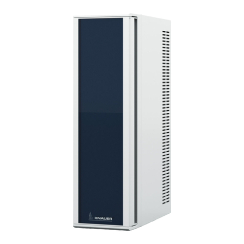
Knauer Azura CT 2.1 User manual

Column Thermostat CT 2.1
Instructions
Document no. V6811
HPLCHPLC

Note: For your own safety, read the instructions and follow the warnings
and safety information on the device and in the instructions.
Keep the instructions for future reference.
Note: In case you require this instruction in another language, please
submit your request including the corresponding document number via
e-mail or fax to KNAUER.
Do you have questions about the installation or the operation of your
instrument or software?
International Support:
Contact your local KNAUER partner for support:
www.knauer.net/en/Support/Distributors-worldwide
Support in Germany
(Austria & Switzerland on case-to-case basis):
Phone: +49 30 809727-111 (workdays 9-17h CET)
Fax: +49 30 8015010
E-mail: support@knauer.net
KNAUER Wissenschaftliche Geräte GmbH
Hegauer Weg 38
14163 Berlin
Germany
Phone: +49 30 809727-0
Fax: +49 30 8015010
Internet: www.knauer.net
E-mail: info@knauer.net
Document number: V6811
Version number: 1.5
Release date: June 26, 2023
Translation of the original edition
These instructions apply to products with the product number:
ATCXXYYZZ
The information in this document is subject to change
without prior notice. For the latest version of the instructions,
visit our website: www.knauer.net/library.
These instructions are printed on recycled paper that has been awarded
the Blue Angel.
This document contains confidential information and may not be
reproduced without written consent of KNAUER Wissenschaftliche
Geräte GmbH.
© KNAUER Wissenschaftliche Geräte GmbH 2023
All rights reserved.
AZURA® is a registered trademark of
KNAUER Wissenschaftliche Geräte GmbH.
Support:
Publisher:
Version information:
Sustainability:
Copyright:

i
AZURA® Column Thermostat 2.1 Instructions, V6811
Table of contents
1. General ...........................................................................1
1.1 About these instructions..................................................1
1.2 Signal words ............................................................1
1.3 Additional typographical conventions ......................................1
1.4 Legal information ........................................................2
1.4.1 Liability limitation.................................................2
1.4.2 Transport damage ................................................2
1.4.3 Warranty conditions ..............................................2
1.4.4 Declaration of conformity..........................................2
2. Basic safety instructions . . . . . . . . . . . . . . . . . . . . . . . . . . . . . . . . . . . . . . . . . . . . . . . . . . . . . . . . . . . . . 3
2.1 Intended use ............................................................3
2.1.1 Operating ranges ................................................3
2.1.2 Foreseeable misuse...............................................3
2.2 User qualification ........................................................3
2.3 Operator responsibility ...................................................4
2.4 Personal safety equipment . . . . . . . . . . . . . . . . . . . . . . . . . . . . . . . . . . . . . . . . . . . . . . . . 4
2.5 Safety features on the device ..............................................4
2.6 Working with solvents ....................................................5
2.6.1 General requirements.............................................5
2.6.2 Contamination by health-threatening solvents ........................5
2.6.3 Avoiding leakage.................................................5
2.7 Specific environments ....................................................5
2.7.1 Earthquake-endangered areas .....................................5
2.7.2 Explosive environment ............................................6
2.7.3 Cooling room ....................................................6
2.7.4 Wet room .......................................................6
2.8 Maintenance, care, and repair .............................................6
2.9 Service request form .....................................................6
3. Product information.................................................................7
3.1 General ................................................................7
3.1.1 Optional accessories..............................................7
3.1.2 GLP data ........................................................7
3.2 Scope of delivery ........................................................7
3.3 Views ..................................................................8
3.4 Symbols and signs .......................................................9
4. Installation and initial startup .......................................................11
4.1 Unpacking .............................................................11
4.2 Ambient conditions .....................................................11
4.2.1 Operation site ..................................................11
4.2.2 Ambient temperature ............................................11
4.2.3 Space requirements .............................................12

ii Table of contents
AZURA® Column Thermostat 2.1 Instructions, V6811
4.3 Power supply...........................................................12
4.4 Computer control.......................................................13
4.4.1 Setting up LAN..................................................13
4.4.2 Configuring LAN settings.........................................13
4.4.3 Connecting devices with LAN .....................................14
4.4.4 Configuring the router ...........................................14
4.4.5 Integrating LAN into the company network .........................15
4.4.6 Controlling several systems separately in LAN .......................15
4.5 Setting IP addresses via software .........................................16
4.5.1 Mobile Control: Setting a static IP address ..........................16
4.5.2 Mobile Control: Setting a dynamic IP address via device name.........17
4.5.3 Mobile Control: Setting a dynamic IP address via device serial number..17
4.5.4 Firmware Wizard: Setting a static IP address.........................18
4.5.5 Firmware Wizard: Setting a dynamic IP address ......................19
4.6 Installing cartridge for eluent pre-tempering ...............................20
4.6.1 Mounting column to precolumn tempering..........................20
4.7 Capillary guide .........................................................21
5. Operation ........................................................................22
5.1 Initial start-up ..........................................................22
5.2 Switching on ...........................................................22
5.3 Control with chromatography software ....................................22
6. Functionality tests .................................................................23
6.1 Installation Qualification (IQ) .............................................23
6.2 Operation Qualification (OQ).............................................23
7. Troubleshooting ...................................................................24
7.1 L AN...................................................................24
7.2 Possible problems and solutions ..........................................25
7.3 Error messages.........................................................25
7.4 Replacing fuses.........................................................26
8. Maintenance and care..............................................................27
8.1 Maintenance contract ...................................................27
8.2 Cleaning and caring for the device ........................................27
8.3 Removing a leak ........................................................27
8.4 Testing the leak sensor ..................................................28
9. Transport and storage..............................................................29
9.1 Taking the device out of operation ........................................29
9.2 Packing the device ......................................................29
9.3 Transporting the device .................................................29
9.4 Storing the device ......................................................29

Table of contents iii
AZURA® Column Thermostat 2.1 Instructions, V6811
10. Disposal ..........................................................................30
10.1 AVV-Marking Germany ..................................................30
10.2 WEEE registration number ...............................................30
10.3 Eluents and other operating materials .....................................30
11. Technical data.....................................................................31
11.1 Main features...........................................................31
11.2 Communication ........................................................31
11.3 General ...............................................................31
12. Repeat orders .....................................................................32
12.1 Device ................................................................32
12.2 Accessories and spare parts..............................................32
13. Index.............................................................................33

AZURA® Column Thermostat 2.1 Instructions, V6811

1
AZURA® Column Thermostat 2.1 Instructions, V6811
1. General
1.1 About these instructions
These operating instructions enable the safe and efficient operation of
the device. The user must have carefully read and understood these ope-
rating instructions before starting any work.
The basic prerequisite for safe operation is compliance with all safety
instructions (see “2 Basic safety instructions“, p. 3). In addition to the
safety and warning instructions in these operating instructions, the local
accident prevention regulations and the national industrial safety regulati-
ons apply.
These operating instructions are an integral part of the device. It must be
kept in the immediate vicinity of the device and accessible to the user at
all times.
You can download these and other instructions from the KNAUER web-
site: www.knauer.net/library
1.2 Signal words
Possible dangers related to the device are distinguished in personal and
material damages.
Symbol Meaning
DANGER (red) indicates a highly hazardous situation.
If not avoided, it will result in death or serious injury.
WARNING (orange) indicates a hazardous situation.
If not avoided, it could result in death or serious
injury.
CAUTION (yellow) indicates a moderate hazardous
situation. If not avoided, it could result in minor or
moderate injury.
NOTICE (blue) is used to address issues which are
not related to physical injury.
1.3 Additional typographical conventions
General equal treatment: When persons are described, this document
uses the male grammar form to keep the text easy to read. The form
has a neutral sense and speaks to people of any gender in the same
way.
Note: Specific information are prefixed with the word “Note” and an
information icon.
Note: This is an example.

AZURA® Column Thermostat 2.1 Instructions, V6811
2 General
1.4 Legal information
1.4.1 Liability limitation
The manufacturer is not liable for the following issues:
Non-compliance of these instructions
Non-observance of necessary safety precautions
Improper use
Operation of the device by unqualified personnel
(see “2.2 User qualification“, p. 3)
Use of non-approved spare parts
Technical changes by the user such as opening the device and
unauthorized modifications
Violations of General Terms and Conditions (GTC)
1.4.2 Transport damage
The packaging of our devices provides the best possible protection
against transport damage. However, check the packaging for transport
damage. In case you notice any damage, inform the Technical Support
and the shipping company within three workdays.
1.4.3 Warranty conditions
For information on warranty please refer to our general terms and condi-
tions on the website: www.knauer.net/terms
1.4.4 Declaration of conformity
The declaration of conformity is enclosed as a separate document with
the product and can be obtained online:
www.knauer.net/en/Support/Declarations-of-conformity

3
AZURA® Column Thermostat 2.1 Instructions, V6811
2. Basic safety instructions
The device has been developed and constructed in such a way that ha-
zards arising from its intended use are largely excluded. Nevertheless, the
following safety instructions must be observed in order to exclude residu-
al hazards.
2.1 Intended use
Only use the device for applications that fall within the range of the inten-
ded use. Otherwise, the protective and safety equipment of the device
could fail.
2.1.1 Operating ranges
The device is intended to be used for chromatographic applications in
the laboratory.
2.1.2 Foreseeable misuse
Refrain from the use of the device for the following purposes or
conditions:
Medical purposes. The device is not approved as a medical product.
Operating outside of a laboratory or measurement room. Otherwise,
the manufacturer does not guarantee the functionality and safety of
the device.
Operation in potentially explosive areas without special and additio-
nal explosion protection. Contact the KNAUER Customer Support for
more information.
2.2 User qualification
The user is qualified to handle the device if all of the following points
apply:
The user has at least a basic knowledge of liquid chromatography.
The user has knowledge about the properties of the used solvents and
their health risks.
The user is trained for the special tasks and activities in the laboratory
and knows the relevant standards and regulations.
Due to technical training and experience, the user can understand and
carry out all the work described in the operating instructions on the
instrument and recognize and avoid possible dangers independently.
The users ability to react is not impaired by the consumption of drugs,
alcohol or medication.
Participation in the installation of a device or a training by the company
KNAUER or an authorized company.
If the user does not meet these qualifications, the supervisor has to be
informed.

AZURA® Column Thermostat 2.1 Instructions, V6811
4 Basic safety instructions
2.3 Operator responsibility
The operator is any person who operates the device himself/herself or
leaves it to a third party for use and who bears the legal product responsi-
bility for the protection of the user or third parties during operation.
The obligations of the operator are listed below:
Know and follow the applicable work safety regulations.
Identify hazards arising from the working conditions at the place of use
in a risk assessment.
Set up operating instructions for the operation of the device.
Regularly check whether the operating instructions correspond to the
current status of the regulations.
Clearly regulate and specify responsibilities for installation, operation,
troubleshooting, maintenance and cleaning and set clear rules.
Ensure that all personnel who work with the device have read and
understood these operating instructions.
Train the personnel who work with the device at regular intervals and
inform them about the dangers.
Provide the necessary safety equipment to the employees working
with the unit (see section below).
2.4 Personal safety equipment
The protective measures required in the laboratory must be observed
and the following protective clothing worn during all work on the device:
Safety glasses with side protection.
Protective gloves in accordance with the prevailing ambient conditions
and used solvents (e.g. heat, cold, protection against chemicals).
Lab coat.
Personalised protective safety equipment which is specified in the
particular laboratory.
2.5 Safety features on the device
Power switch: Devices of the AZURA® L series may be switched off
using the power switch (toggle switch on the back side of housing) at
any time, this causes no damage to the device. To switch off devices of
the AZURA® S series, remove the plug from the power socket.
Front cover as a splash protection for the user.
Leak tray: Devices of the AZURA® L series have a leak tray on the front
side. The leak tray collects leaking solvents and protects components
from potential damage caused by discharging liquid.
For the detectors AZURA DAD 2.1L, DAD 6.1L und MWD 2.1L, the
lamp switches off automatically when the cover is opened.

AZURA® Column Thermostat 2.1 Instructions, V6811
Basic safety instructions 5
2.6 Working with solvents
2.6.1 General requirements
The user is trained for handling different solvents.
Note that organic solvents are toxic above a certain concentration. For
handling hazardous solvents see the following section.
Mobile phases and samples may contain volatile or combustible sol-
vents. Avoid the accumulation of these substances. Ensure good ven-
tilation of the installation site. Avoid open flames and sparks. Do not
operate the instrument in the presence of flammable gases or vapors.
Only use solvents which do not self-ignite under given conditions. This
applies especially to the use of a thermostat where liquids could get
onto hot surfaces in the interior.
Certain chemicals can cause PEEK capillaries to swell or burst. Please
read the technical literature on chemical compatibility of PEEK before
use.
2.6.2 Contamination by health-threatening solvents
Contamination with toxic, infectious or radioactive substances poses
a hazard for all persons involved during operation, repair, sale, and dis-
posal of a device.
All contaminated devices must be properly decontaminated by a spe-
cialist company or the operating company before they can be recom-
missioned, repaired, sold, or disposed (see “10 Disposal“, p. 29).
2.6.3 Avoiding leakage
Risk of electrical shock or short circuit if solvents or other liquids leak into
the interior of the device. You can avoid a leakage through the following
measures:
Tightness: Visually check the device or system regularly for leaks.
Solvent tray: The use of a solvent tray prevents liquids get from the
bottles into the inside of the device.
Eluent lines: Install capillaries and hoses in such a way that, in case of a
leak, liquids cannot get into the interior of the devices underneath.
In case of leakage: Switch off the system. Only take the device into
operation if the cause of the leak has been resolved (see “8 Mainte-
nance and care“, p. 27).
2.7 Specific environments
2 .7.1 Earthquake-endangered areas
In earthquake-endangered areas, do not stack more than 3 devices on
top of each other. Otherwise there is risk of injury due to falling devices
or loose parts.

AZURA® Column Thermostat 2.1 Instructions, V6811
6 Basic safety instructions
2 .7. 2 Explosive environment
Never use the system in potentially explosive environments without
appropriate protective equipment. For more information, contact the
KNAUER Customer Support.
2 .7. 3 Cooling room
Note: When the AZURA® CT 2.1 is operated in a cooling room, devia-
tions from the specifications of the heating/cooling rate, temperature
accuracy and temperature stability are possible (see “11 Technical data“,
p. 31).
You may operate the device in a cooling room. To prevent condensation,
note the following instructions:
Allow the device to acclimatize for min. 3 hours before taking it into
operation.
After taking into operation, the device should stay switched on.
Avoid temperature fluctuations.
2 .7. 4 Wet room
The device must not be operated in wet rooms.
2.8 Maintenance, care, and repair
Avoiding electric shock: Before performing any maintenance and ser-
vice work, disconnect the device from the power supply.
Tools: Use only tools recommended or prescribed by the
manufacturer.
Spare parts and accessories: Only use original parts and accessories
made by KNAUER or a company authorized by KNAUER.
PEEK fittings: Use PEEK fittings only for a single port or brand-new
PEEK fittings in order to avoid dead volume or not exactly fitting
connections.
Column care: Follow KNAUER or other manufacturer's instructions on
caring for the columns (see www.knauer.net/columncare)
Used capillaries: Do not use any used capillaries elsewhere in the
system in order to avoid dead volumes, not exactly fitting connections
and spreading contamination.
Safety features: The device may only be opened by the KNAUER Cus-
tomer Support of KNAUER or any company authorized by KNAUER
(see “1.4.1 Liability limitation“, p. 2).
For more information visit the KNAUER website:
www.knauer.net/hplc-troubleshooting.
2.9 Service request form
Devices which are shipped without the completed document “Service
request form and decontamination report” will not be repaired. If you
would like to return a device to KNAUER, make sure to enclose the com-
pleted document: www.knauer.net/servicerequest.

7
AZURA® Column Thermostat 2.1 Instructions, V6811
3. Product information
3.1 General
The AZURA® Column Thermostat CT 2.1 can be used in the following
configurations:
Up to 8 columns of dimensions 125 mm x 4.6 mm ID with precolumn
Up to 4columns of dimensions 300 x 4.6 mm ID
1 column of dimensions 300 mm x 16 mm ID.
A constant temperature between 5-85°C can be selected.
3.1.1 Optional accessories
The following optional accessory is available:
Element for eluent pre-tempering to ensure that the mobile phase is
on the set temperature before entry into the column.
3.1.2 GLP data
With the help of various software packages (e.g. ClarityChrom®or
OpenLAB®), it is possible to display or read the GLP data of the thermo-
stat. You find a detailed description on how to read out GLP data in the
respective user instructions.
3.2 Scope of delivery
In the scope of supply of the device should these items be included:
Device AZURA® Column Thermostat CT 2.1
Power supply cable
Network cable
Valid documents:
Operating Instructions
Installation Qualification (“IQ”)
Declaration of Conformity

AZURA® Column Thermostat 2.1 Instructions, V6811
8 Product information
3.3 Views
Front view
Legend
1
Cartridge for eluent
pre-tempering
(optional)
2
Door
3
Housing
4
Column holder
5
Fan
6
Temperature sensor
7
Column
(not included in the
scope of delivery)
8
Leak sensor
Fig. 1: Front view
Rear view
Note: Please note that the RS-232 interface (“service interface”) is solely
used for repair and maintenance tasks performed by service technicians.
Legend
1
Service interface
2
LAN connector
3
Serial number and
symbols (see chap. 3.4
on p. 9)
4
Fan
5
Power switch
6
Fuse holder
7
Power supply
connection socket
Fig. 2: Rear view
1
4
2
3
5
6
7
8
1
4
2
3
5
6
7

AZURA® Column Thermostat 2.1 Instructions, V6811
Product information 9
3.4 Symbols and signs
The following symbols and signs can be found on the device:
Symbol Meaning
Electric shock hazard. Failure to observe this
warning may result in loss of life, serious injury or
damage or destruction of the device.
Electrostatic discharge hazard. Damages to system,
device, or sensitive electronic components can
occur.
Danger from hot surface. If not observed, burns
may result.
A warranty seal is affixed to some devices.
The device is covered by the Waste Electrical and
Electronic Equipment Directive (WEEE Directive).
It may not be disposed of as unsorted municipal
waste and must be collected separately
(see chap. 10 on p. 30).
The device fulfills the product specific requirements
of European directives.
The device complies with the product-specific
requirements of the United Kingdom.
The device has successfully passed the TÜV tests
for quality and safety. The TÜV Germany is a natio-
nally recognized testing agency (NRTL) in Canada
and the USA.
The electromagnetic interference from the device
is below the limits approved by the Federal Com-
munications Commission (FCC).
The device complies with the Australian EMV
regulations.
CAN ICES-3 (B) The device complies with Industry Canada license-
exempt RSS standards.

AZURA® Column Thermostat 2.1 Instructions, V6811
10 Product information
Symbol Meaning
The device can be used for 15 years according to
its intended use before there is a risk that the con-
tained substances may escape and thereby pose a
risk to the environment and health.

11
AZURA® Column Thermostat 2.1 Instructions, V6811
4. Installation and initial startup
Before you determine the operation site, read the chapter “Technical
Data” (see chapter 11 on page 30). There you will find all device-speci-
fic information on power supply, ambient conditions and humidity.
Note: The intended use be ensured only if the requirements for ambient
conditions of the operating environment are met.
4.1 Unpacking
Process
1. Place the packaging in such a way that the lettering on the label is
in the correct position.
2. Check the packaging, the device and the accessories for transport
damage.
3. Check the scope of delivery. In the event of incomplete delivery,
contact Technical Support immediately.
Keep the included packing list for repeat orders.
Keep the original packaging for safe storage or transportation.
4.2 Ambient conditions
4.2.1 Operation site
Observe the following requirements for the operation site so that the
measurement results are not influenced:
Place on a firm, level and straight surface.
Protect against direct sunlight.
Do not expose to air drafts such as air conditioning systems.
Do not set up the to other machines that cause floor vibrations.
Keep from high frequency sources.
Ensure adequate ventilation (see 4.2.3 on page12 ).
Avoid temperature fluctuations. (see 4.2.2 on page11 )
4.2.2 Ambient temperature
If the ambient temperature of the device is abruptly changed (e.g. when
it is installed in a cooling chamber), condensation will form inside the
device and may cause damage to the device. Allow the device to accli-
mate for 3 h, before it is connected to the power supply and taken into
operation.
Procedure
Next steps

AZURA® Column Thermostat 2.1 Instructions, V6811
12 Installation and initial startup
4.2.3 Space requirements
Make sure that the power plug on the power supply (wall socket or
power strip) is always accessible, so that the device can be disconnec-
ted from the power supply.
Ensure adequate ventilation around the device, otherwise it may over-
heat and malfunction:
- Min. 5 cm distance if another device is set on one side.
- Min. 10 cm distance if further devices are set on both sides.
- At least 15 cm to the cooler fan on the rear.
4.3 Power supply
Power supply requirements
Failure-free power supply: For failure-free operation, the electrical
voltage must be free of fluctuations, residual currents, voltage peaks
and electromagnetic interference. The device must receive sufficient
voltage and reserve capacity.
Check voltage: Only connect devices to a power supply whose voltage
corresponds to the permissible voltage of the device.
Power consumption: The nominal power of the connected devices
must not exceed 50 % of the highest connected power capacity, since
higher currents can flow briefly when the device is switched on.
Main connection: The electrical power supply at the operation site
must be connected directly to the nearest main power connection.
Grounding: The connectors for the voltage must be grounded
accordingly.
Power supply cables and plugs
Original parts: For power supply, use the supplied power cable and
plug to meet the specifications which are described in the chapter
“Technical Data” (see chapter 11 on page 30). Detachable power
cable cables are not allowed to be replaced with other cable types.
Country-specific plugs: Before switching on the device, check whether
the supplied plug is approved for your country. Overview of the de-
vice- and country-specific plug types from KNAUER:
www.knauer.net/plugs
Power strips: If several devices are connected to one power strip,
always consider the maximum power consumption of each device.
Access to power supply: Make sure that the power plug on the power
supply (wall socket or power strip) is always accessible, so that the
device can be disconnected easily from the power supply.
Damaged power supply cables and plugs: For safety reasons, dama-
ged or faulty cables and plugs must not be used to connect the device
to the power supply. Replace defective cables and plugs only with
KNAUER accessories.

AZURA® Column Thermostat 2.1 Instructions, V6811
13Installation and initial startup
4.4 Computer control
Note: HPLC devices from KNAUER only work with IP addresses, which
have been assigned by IPv4. IPv6 is not supported.
This chapter describes how to set up a chromatography system in a local
area network (LAN) and how a network administrator can integrate this
LAN into your company network. The description applies to the operating
system Windows® and all conventional routers.
Note: When using PurityChrom®, static IP addresses are needed
(see chapter 4.4 on page 13).
4.4.1 Setting up LAN
To set up a LAN, we recommend to use a router. That means the following
steps are required:
Process
1. On the computer, go to the control panel and check the LAN
properties.
2. Hook up the router to the devices and the computer.
3. Set up the router for the computer network.
4. Install the chromatography software.
5. Switch on the device and run the chromatography software.
Configure LAN properties (see section 4.4.2).
4.4.2 Configuring LAN settings
The LAN uses only one server (which is normally the router) from that the
devices automatically receive their IP address.
In Windows, power saving, hibernation, standby, and screen saver
must be deactivated.
Applies to all LAN devices: Disable the setting for the network adapter
in Device Manager ”Allow the computer to turn off this device to save
power”.
Process
1. In Windows, open <Network and Sharing Center>.
2. Double-click on <LAN connection>.
3. Click on the button <Properties>.
4. Select <Internet Protocol version4 (TCP/IPv4)>.
5. Click on the button <Properties>.
Procedure
Next steps
Prerequisites
Procedure

AZURA® Column Thermostat 2.1 Instructions, V6811
14 Installation and initial startup
Process
6. Check the settings in the tab <General>. The correct settings for
the DHCP client are:
a) Obtain an IP address automatically
b) Obtain DNS server address automatically
7. Click on the button <OK>.
Connect devices (see section 4.4.3).
4.4.3 Connecting devices with LAN
A router 2has several LAN ports 3and one WAN port 4that can be
used to integrate the LAN into a wide area network (WAN), e.g. a com-
pany network or the Internet. In contrast, the LAN ports serve to set up a
network from devices 1and a computer 5. To avoid interference, we
recommend operating the chromatography system separately from the
company network.
Note: You will find patch cables for each device and the router in the
accessories kit. To connect the router to a LAN, an additional patch cable
is required, which is not supplied within the scope of delivery.
Legend
1 Devices
2 Router
3 LAN ports
4 WAN/Internet
connection
5 Computer
1 2 3 4 5
Fig. 3: Connecting the devices to the LAN
The computer is switched off.
There is a patch cable for each device and the computer.
Process
1. Use the patch cable to connect the router and the computer.
Repeat this step to connect all devices.
2. With additional patch cables, connect all devices individually with
the router.
3. Use the power supply to connect the router to the mains power
system.
Set the router properties (see section 4.4.4).
4.4.4 Configuring the router
The router is preset at the factory. Information about address, user na-
me and password is noted in the router manual: www.knauer.net/en/
Support/Library/PC-hardware
Next steps
Prerequisites
Procedure
Next steps
Other manuals for Azura CT 2.1
2
Table of contents
Other Knauer Thermostat manuals
Popular Thermostat manuals by other brands

MasterStat
MasterStat 110423-2 installation instructions

Selmo Electronics
Selmo Electronics MUSA Plus Eco manual

Blaufoss
Blaufoss Smartbox Luxe 38407 installation guide

T&D
T&D TR-7wf Introductory manual

suntouch
suntouch 500750-BB Installation & operation manual

Siemens
Siemens Free Energy Band TH 193 HC Technical instructions

Skytech
Skytech 5320 Installation and operating instructions

Prostat
Prostat OEM Series User& installer's manual

MCOHome
MCOHome MCOEMH7H-WH2 quick start guide

Skytech
Skytech TS/R-2A Installation and operating instructions

Lily Tech
Lily Tech ZL-330A instruction manual

ECOheat
ECOheat Connect+ instruction manual