BLO-BLADES OM-KQ-7E User manual
"Open" Large Fans Assembly drawing
………………2-3
1.
Introduction ……………………………………4-7
2. Safety Issues ………………………………7-8
3. Pre-Installation ………………………9-12
4. Installation Procedure & Sequence......................13-19
5.
Electrical installation ……………………19-21
6.Guy Cabling BloBlades ………………………22-23
7.Start-up procedure
…………………23-24
8. Cleaning And User Maintenance ………………24-25
9.General trouble shooting
……………………………26
10.
Letter of Warranty ………………………………27
11. Limitation of warranty and liability
………………28-29
Blo-BladesContents
大型风扇行业的领航者
3
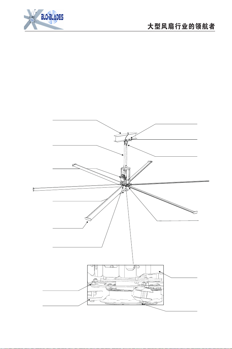
BloBlades Large Fans Components
6ea
Fan
T
ail
Caps
1ea R
oof
Fastening
A
ssembly
6ea
Fan
B
lade
C
onnector
Airfoil Safety
R
etainer
Plug In
B
ottom
C
over
Main
M
otor
1ea
Universal
J
oint
A
ssembly
Structural Support
of the building
- Typical
I Beam 4ea
M16
Nut/Bolt
1ea
Extension
B
ar
- Other
Lengths Available
1ea
Ho
i
st
A
ssembly
6ea
Fan
B
lade
I
nterconnection
Safety
Assemblies
1ea Fan
C
over
-
6ea Fan Blades
Introduction
1.1.Thank you and congratulations on your BloBlades Fan purchase, Younow have
an
efficient and cost effective way to stay cool in summer and warm in the winter. The
sleek revolutionary design of our fans will look great in any commercial or industrial setting.
More importantly, you can rest assured that you have a product that is backed by
extensive research, thorough testing, and quality manufacturing.
If you have any questions or comments, contact us at 833-BLO-FANS or visit our web site
at www.BloBlades.com
1.2 BloBlades represents the number one and leading manufacturer of HVLS Fans,
for
large industrial fans with large coverage and in all directions. For
many decades, there
has been focus on only one thing: HVLS Big Fans development and
innovation,which
are widely use in large warehouses & distribution centers, manufacturing
facilities and
commercial buildings with high ceilings to deliver maximum airflow,Our fans
are not
only the most reliable and efficient ever built, but have also been proven to be the
professional's choice for ventilation needs in large space.
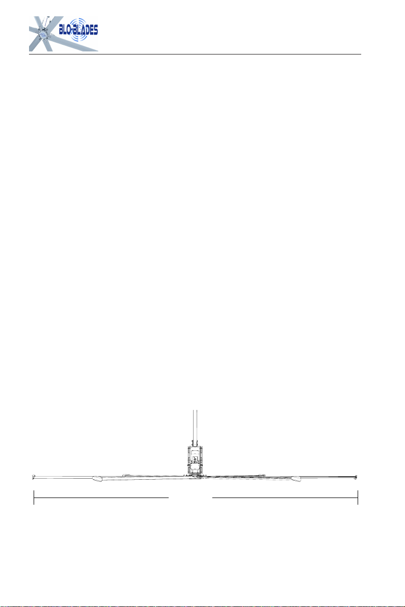
1.3 About this Fan
1.3.1
Fans Diameter: 12FT-24 FT/3.7-7.3 Meters
1.3.2 Each fan has six airfoil fan blades; Aluminum alloy, anodized treatment after the
sand blasting and chemical polishing.
4
12' - 24'

大型风扇行业的领航者
1.3.3 Fans Hub:American AA7075 extremely
hard
aluminum alloy,
with high
pressure
precision
forging
forming, dynamic
balancing
test
after
CNC
precision
machining.
1.3.4
Reduction Gear
Germany - NORD SK32F-VL90L/4 coaxial helical gear reducer.
Output shaft uses the SKF VL taped roller bearing, Shell Omala VG680 synthetic gear oil
has 20,000 hours of free maintenance; The output shaft uses Freudenberg Simrithigh
temperature double lipped output oil seal; Gear Box automatic exhaust valve;New
generation
energy-efficient
level
4
motor
with
NEMA
IE2
Standards,
220V/480V/60HZ IP55/F,IM:M4/4/I; Power: 1.5kw;50/60 HZ;480/220V
5

6
1.3.5 Motor Control Panel
(MCP)Danfoss FC51 Built-in RF line filters and brake chopper, with radio functionality
interference suppression and brake
- The functions of ground fault protection、
higher temperature protection, short-circuit
protection and etc.
- Stepless
speed
regulation,
The
peripheral
speed and switch gear
- NEMA
standards
control
box,
PVDF
paint surface treatment.
- IP65 protection class, CAKU cooling fan forced ventilation
- The operation instructions and warning labels are printed in control box.
3Ph/480V/60Hz or 1Ph/220V/60hz are available for power supply.
1.3.6 Safety System Components
BloBlades "Open" fans are engineered with key safety features to prevent pieces of the
fan from
falling in the unlikely event of a catastrophic failure. Used together, these
systems and
devices provide comprehensive protection of people, equipment, and
property. Follow the
detailed instructions precisely when installing fans, including the
following: You must install safety cable for warranty to be in effect.
It completely eliminates
the
riskof
falling
down
due to failure
ofthe hub
or drive shaft connection
of the six extension
blades.
大型风扇行业的领航者
7
Safety issues
IMPORTANT SAFETY INSTRUCTIONS, READ AND SAVE THESE INSTRUCTIONS
警告:
WARNING—TO
REDUCE
THE
RISK
OF
FIRE,
ELECTRIC
SHOCK,
OR
INJURY
TO
PERSONS, OBSERVE THE FOLLOWING:
2.1 Installation work and electrical wiring must be done by qualified person(s) in
accordance with all applicable codes and standards.
CAUTION:
The installation of a BloBlades "Open" fan must be in accordance with the
requirements
specified in this User manual and with any additional requirements set forth
by the national electric code. Code compliance is ultimately YOUR responsibility!
WARNING:
The fan controllers contain high voltage capacitors which take time to
discharge after removal of mains supply.
Before working on the fan controller, ensure isolation of main supply from line inputs at
Safety links should be connected each blade and to the adjacent blades and reinforce the
area between the mounting holes, this precautionary measure will help prevent a blade
from falling should one break off at the hub for any reason.
The four guy wires will keep the fan stable in case of earthquake or in "outdoor"
installations where high wind conditions may occur or indoor situations that may have
drafts that affect the balance of the fan.
6mm (approx 1/4") safety cable will prevent the fan from falling in the unlikely event the
mounting system
should fail.
Hanging Weight (average) :207lbs---276lbs

8
the fan controller's disconnect (L1,L2/N, L3). Wait 3 minutes for capacitors to discharge
to safe voltage levels (note: darkened display LEDs are not an indication of safe voltage
levels). Failure to do so may result in personal injury or death.
CAUTION:Exercise caution and common sense when powering the fan. Do not connect
the fan to a damaged or hazardous power source. Do not attempt to resolve
electrical malfunctions or failures on your own. Contact BloBlades at
833-Blo-Fans
if you have any questions regarding the electrical
installation
of
this fan.
2.2 A scissor lift or movable scaffolds for lifting weight of the fan and at least two
installation personnel will be required, please check and confirm its safety &
reliability,
and each person installing the fans on the site must use a helmet and safety
harness at all
times.
BloBlades Fans must be installed with the BloBlades supplied controllers which are
suitable with this model. Other parts or controllers cannot be substituted.
CAUTION:
When service or replacement of a component in the fan requires the removal
or disconnection of a safety device, the safety device is to be reinstalled or
remounted as previously installed.
2.3 WARNING—TO
REDUCE
THE
RISK
OF
FIRE,
ELECTRIC
SHOCK,
OR
INJURY
TO PERSONS, OBSERVE THE FOLLOWING:
a) Use this unit only in the manner intended by the manufacturer. If you have
questions, contact the manufacturer.
b)
Before servicing or cleaning unit, switch power off at service panel and lock the
service disconnect to prevent power from being switched on accidentally. When
the
service disconnect cannot be locked, securely fasten a prominent warning
device, such as a tag, to the service panel.
CAUTION:
Do not bend the blades when installing, adjusting, or cleaning the fan. Do not
insert foreign objects in between rotating fan blades.
CAUTION:
The Bloblades Fans product warranty will not cover equipment damage or
failure that is caused by improper installation.

大型风扇行业的领航者
Pre-Installation
3.1 3.1
Check lists before installation
Installation Tools
Level; Pliers; Cable Cutters; M8-M10 (2 sets outer hexagonal wrench); Scissor Lift or
Scaffold; Wrench 4 sets; Phillips Screwdriver; Electric Drill; M4.2 bit;
Torque Wrench; M8-M30 Socket Wrench
Typical mounting methods
Each type of building structure requires a specific mounting bracket, BloBlades
Fans can
only be hung from standard mount with an I-beam or concrete beam. For
buildings with
glulam beams (laminated wood), an additional set of brackets is required
and can be purchased separately. Consult a structural engineer for installation methods.
1)
Verify with the contractor, building owner, or structural engineer to ensure the building
structure is sound and adequate to support the load prior to fan installation.
2)
Take measurements of the height of the bottom of I-beam and blade level.
3)
Check if you have the correct power circuit for the fan.
3.2 General Mounting Considerations
CAUTION:
Bloblades Fans product warranty will not cover equipment damage
or
failure that is caused by improper installation.
3.2.1 Weight
A standard six blade 24' fan which is the biggest fan is about 276lbs. In applications
where the
Motor is inverted to below upward (very unusual) there is an additional down
force of 110lbs. Due to fan thrust. If there is any doubt of this, a professional structural
engineer should perform a thorough evaluation of the building prior to purchasing fans
BloBlades Fans can only be hung from an I-beam or concrete beam and angle irons on
main structure of building. Do not mount the fan to single purlins, trusses, or bar
joists. Consult a structural engineer for installation methods not covered in the manual.
9
3.2.2 Torque
The maximum torque (twisting force) that must be handled by the mounting systems
occurs at start up. For a 24' BloBlades Fan the starting torque is potentially 220 N.m.
Maximum. We say "potentially" because with the standard electrical controls supplied,
the
maximum
is
never
even
approached
because
the
controls
employ
soft
start
technology. This prevents full torque from being applied at startup. But there is always the
possibility of failure of the soft start technology. It is important that the mount is
adequate to withstand 220 N.m.
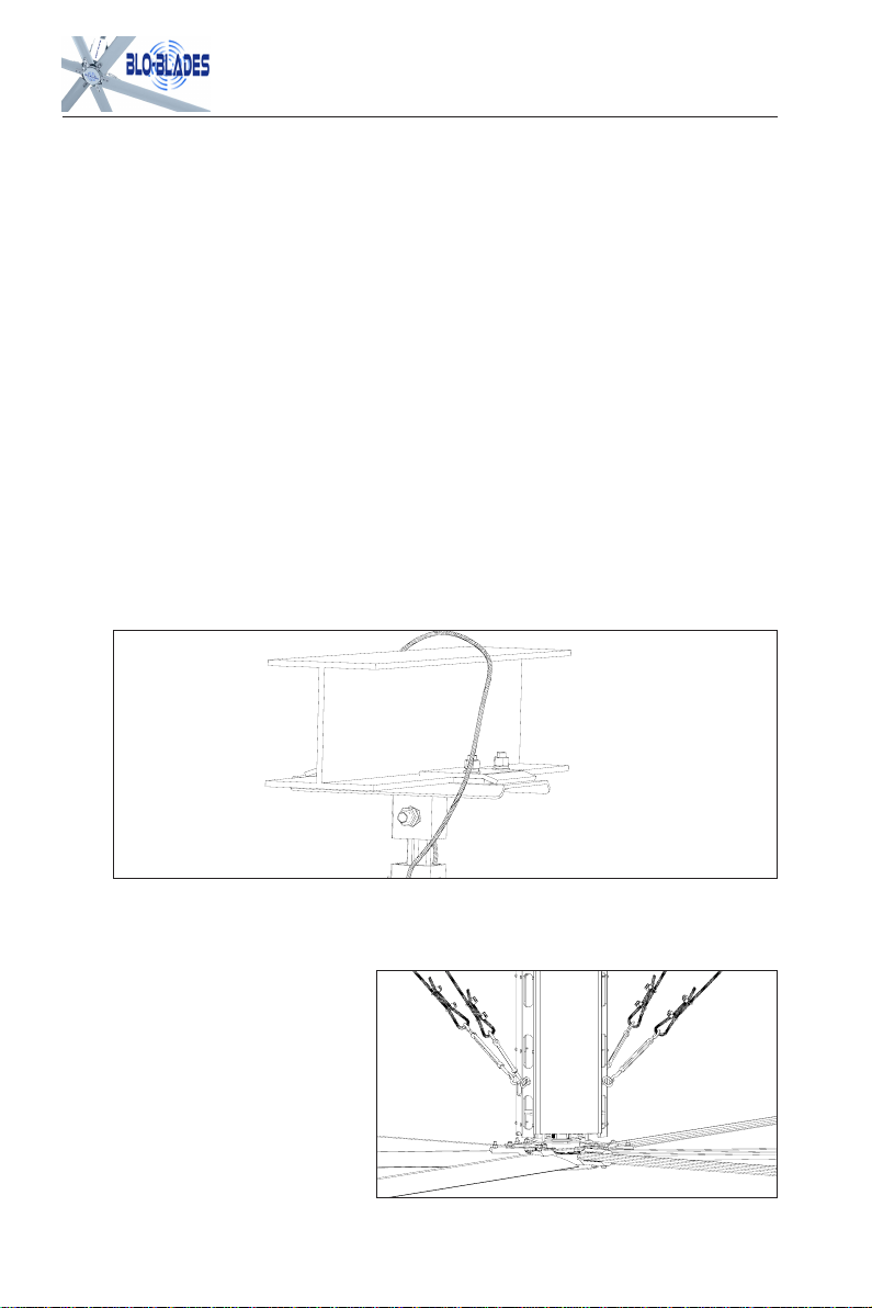
3.2.3 Safety Cable
Because of the obvious risk of a falling fan, whatever mounting method is used to suspend
the fan, it should always be backed up with a safety cable.
Safety cable, along with all required hardware, is supplied with every fan. An HVLS fan
should never be run without a properly installed safety cable. Refer to fig. 3.1 for
proper installation of safety cable.
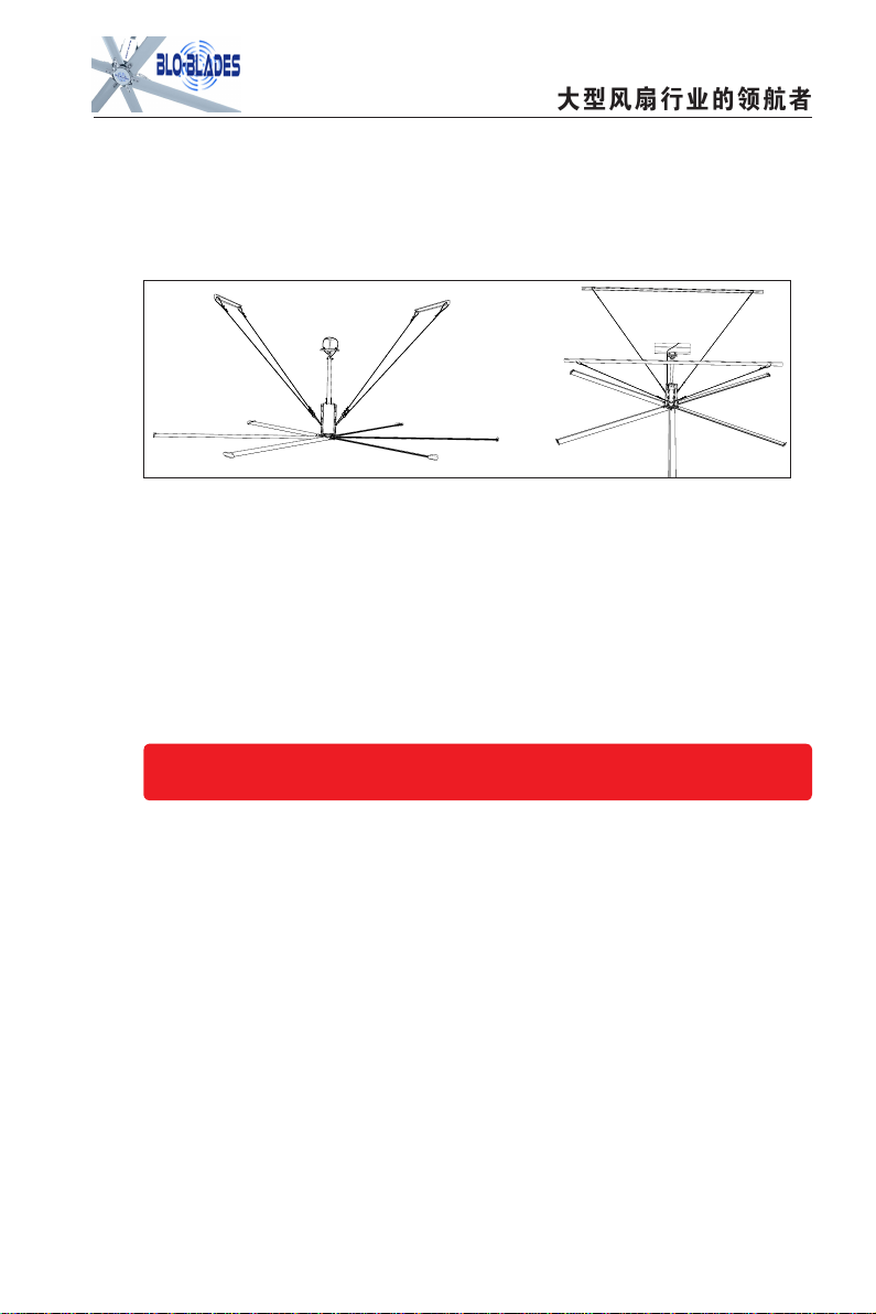
3.2.4
Clearance and Guy Cables
In some cases space
considerations dictate that
blades swing
close
to
beams,
column, lights, etc. Anything less
than 12" can be considered "close
clearance”because these fans
have the potential to move around
quite a
bit.
Fig3.2 Install methods of Guy Cables
10
Fig3.1
OODNO G GOOD

大型风扇行业的领航者
It is important to try to avoid close clearance. Where clearance turns out to be a real
problem, bear in mind that both longer down extension rods and shorter blades are
available for purchase. In any case, since the standard mounting is free swiveling, we
strongly recommend that all fans be guy wired as shown in fig.3.2. if close clearance is
involved, the fan must be guy wired. Where the fan frame is bolted directly to a rigid
beam, it may not require guy wiring.
3.3. Positioning
It is important that an HVLS fan not be positioned where a person could actually come in
contact with it. This means that a fan should never be mounted lower than 10' above the
floor. Similarly, if there is a mezzanine section in the facility, it is important that a fan not be
placed so close to the mezzanine, that a person on an upper tier could reach out and
contact the fan.
Wherever there is a potential for a forklift to elevate something into the fan, or people
working with long material inadvertently making contact with the fan, the floor directly
below the fan should be painted in such a way (i.e. a large crosshatched circle) so as
to alert workers to the fan above. In such cases, the fan may have to be guarded.
3.3.1
Horizontal Positioning
The way these fans spread air flow over such a large area is that the down flowing
11
4.5
Fig3.2 Install methods of Guy Cables
8"
12"
14.5'- 49'
12"
143.5"
42"

air column, upon reaching the floor, turns into a horizontal floor jet radiating out in all
directions. Under ideal conditions a 24' diameter overhead fans can serve up to
19,375sq/ft of floor space. Ideal conditions are: a fairly symmetrical area equates to
very few obstructions on the floor, and walls at the boundary of the area.
Obstructions on the floor, such us partitions or machinery tend to block the floor jet,
reducing the reach of the fan. The ideal center to center spacing, therefore, will vary
depending on the amount and size of these floor obstructions, as well as the nature of the
operations being conducted in the affected area and the construction of the building (i.e.
beams, etc.). In a manufacturing environment where there are many work stations each of
which must get good air movement, a solution is fans with close centers, running slowly.
For example, 24' long blade fans located on 60' centers, running at about 53rpm, might
be appropriate.
Conversely, in a warehouse where workers are moving around a lot and a little windiness
here and there is not a problem, 24' long blade fans on 110' centers might be suffice.
3.3.2 Vertical positioning
In many applications physical limitations——overhead cranes, low ceilings, etc.-dictate
vertical positioning, Where there is some latitude, here are the primary points to consider:
From a strictly performance point of view, 19.5' to 33' is the optimum height range for a
24' fan, but we have seen fans mounted as low as 9.75' and as high as 52.5' working
well. (HVLS fans should never be lower than 9.75' above the floor)
A fan must not be so close to the ceiling that is starved of air; it should be no less than
15% of its diameter from the ceiling. If the ceiling is pitched,the blades can come closer
on one side so long as there is ample open area on the other side.
If possible, fans should be high enough to be beyond the reach of forklifts and any long
material that workers might be handling.
Conversely, where fans are used to cool people working in just one part of very large
building with a very high ceiling, lower mounted fans may be in order. In such an extreme
case high mounted fans would re-circulate cooler air, leveling the hot air undisturbed.
12
大型风扇行业的领航者
Installation Procedure & Sequence
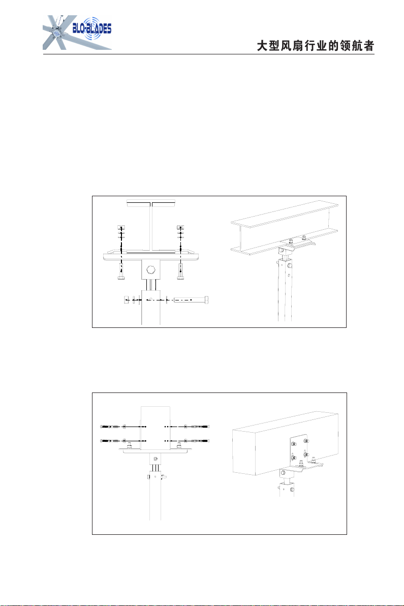
4.1 Equipment and Beam Connection
There are two standard installation methods that the fan is connected to the
(1)Connection with Steel I-beam by adjustable standard clip device, the fan can be easily
clip on any steel I-beam, without the need to change any steel beam (figure 4.1).
(2)Connection with concrete beam, the standard device is fixed by expansion bolts on the
concrete beam, the device can be adjusted according to the width of the beam, meeting
the
demand of concrete beams with different dimensions .
(3)If your facility has another structure please call (833-BLO-Blades) for potential
mounting options.
13

Note:
If
the beam is level,it is sometimes OK to bolt directly to the I-beam e.g.
14
Fig4.1 Installation Method of I-Beam
4.2 Installation of the Universal Joint
The standard mounting hardware that comes with an BloBlade fan has a 300mm
extension or drop, and clamp designed for use on a steel I beam without modification to
the beam (fig.4.2). since beams are often sloped so the roof can shed water, and not all
roofs slope the same, the mount is free- swiveling. This allows the fan to find its own level
position no matter what the slope.
Fig4.2
Univisal Joint

大型风扇行业的领航者
if head room is a problem-as long as there is adequate“breathing room” above the fan.
But, be advised that sometimes a fan would run with almost no sway when hung from our
free swiveling mount, will sway radically when bolted directly to a lightweight beam of
commonly found in steel building. This is because a slight imbalance can, at a certain
rpm, excite the natural frequency of the beam in torsion, thereby amplifying the sway. Also,
without the free swiveling mount, more noise is telegraphed back to the building structure.
4.3
Installation of the drive device
(1)The drive device has been installed into a unit before shipping out, only fix it to the
extension rod by using bolts, as shown in figure 4.3.
(2)Due to the drive device weight, 2-3 people are
needed to install. If there is a scissors lift, you can use the
lift to assist in assembly, the hoisting weight of the lifting
equipment shall not be less than 440lbs, the hoisting
process must be slow, even, and at the same time it needs
someone to hold the drive device, to prevent oscillation.
(3)Do not remove oil plug until fan is properly mounted. If
the oil plug is removed before the fan is mounted, oil in the
gear reducer may spill out.
4.4
Run the conduit and install wiring,
(1)
along the facility structure, along the top of the beam layout, per code.
15
Fig4.3
Installation of the driving unit
(2)Run
the wire conduit layout in as short of a run as possible.
(3)Before wiring, be sure to have the power supply turned off and then wire the motor circuit,
if the factory power supply is 480V, connect the motor according to the Y type
connection wiring,
if the factory power supply is 220 V, the motor according to the
△connection
wiring.
(4)After the motor wire has been connected, then connect the electric wires to the
electric cabinet.
4.5 Installation of the guy wires
Each BloBlade Fan has four circular uniform guy wires, try to ensure that the angle
between each gay wire and the drive device is 45 °, too big or too small will effect the
guy wire. The function of the guy wire is mainly the following:
(1)To reduce the fan shake when running.
(2)The guy wires ensure that the level of the fan, improve the dynamic balance of the fan.
(3)The safety protection devices to prevent falling the fan.
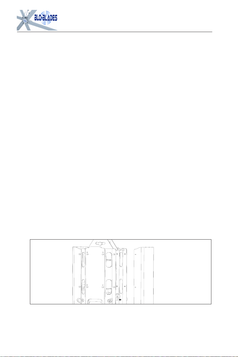
4.6 Installation of the outer shell
From both sides assemble the two outer shells to the drive device, then adjust and align
with screw and fasten, lack of bolts or didn't lock is not allowed, the outer shell less
shaking is also not allowed, as shown in figure 4.4
Fig4.4 Installation of the outer shell
16

大型风扇行业的领航者
4.7 Attach Winglets to Air Foil Blades
Attach the winglets to the airfoil using the Winglet Hardware as shown in figure 4.5. You
will
need to use Philips screwdriver to properly secure the fasteners. Attach winglets
to
all six (6) airfoils before attaching the airfoils to the fan.
4.8
Attach Airfoils to Hub
(1)WARNING:
Disconnect power to the fan before installing the airfoils.
(2)Slide the airfoils onto the tabs of the fan hub. This is usually done after the motor/hub
assembly has been mounted and the guy cables have been installed. The blades
should
slide on easily, if not, a little finesse works better than force. Refer to fig.4.6 to
make sure
you
are installing the blades facing the right way. An airfoil will only attach to the
fan hub in one direction. Do not force an airfoil into place.
(3)The bolt holes on the blade and the bolt holes on the Hub align.
17
图 4.5
Fig4.5

(4) Attach the (6) airfoil retainers using the Airfoil Hardware. Moving clockwise around the
fan
hub, position the airfoil retainers end over end as shown in figure 4.7. Do not tighten
the bolts until all the airfoil retainers have been attached.
First, tighten the bolts along the outside perimeter to 29 ft·lbf (39 N·m) using a
Socket with torque wrench;
Second, tighten the bolts along the inside perimeter to 29 ft·lbf (39 N·m) using a
Socket with torque wrench;
4.9
CAUTION:
Do not bend the blades when installing, adjusting, or cleaning the fan. Do
notinsert foreign objects between rotating fan blades.
Installation of bottom cover with LOGO
Take
the
bottom
cover
close
to
the
blade
wheel,
bolt
holes
alignment,
bolts
tightened, make
sure
no
bolts
are missing or loose, the bottom
cover does not move after
installation, as shown in figure 4.8
Fig4.7Attach (6) safety ring to Airfoil
Fig4.8 Installation of bottom cover with LOGO
4.10
Checking Strength and
Clearance
If there is any doubt in your mind as to the ability of building structure to which you are
mounting to handle the weight of fan a structural engineer should be consulted.
18

大型风扇行业的领航者
Electrical installation
5.1
Control Options
BloBlades series HVLS fans are driven by standard three phase, dual input voltage
(220V/480V) motors. Standard single fan control panels available from BloBlades
include, a variable frequency drive, a control switch , and an enclosure. They are available
for single phase inputs of 220 volts, and for three phase inputs of 480v.
The VFDs in these control panels are preprogrammed for proper normal operation of the
fan. The factory can assist you in configuring them to receive special inputs-i.e. If you
want the fans to be controlled from a remote location, or want them go on and off at certain
19
After making sure safety cables are installed, an easy way to test the mounting's ability t
o
handle the torque is to insert a 3-5' long 2x4 in the motor frame and try to twist it
as
shown in fig.4.10. if the fan is hanging from an extension you will have to use one hand
on the 2x4 and the other on the motor frame so as to create a torque without exerting a
big
side load. The mount should withstand a 110lb force applied 3' from the center of fan.
Lastly, if there is any potential for a clearance problem, before you start the fan for the first
time, rotate it one time by hand to find the position and blade of least clearance. Grasp
the blade and shake it vigorously both up and down and in and out, make sure there is no
chance of it hitting the obstructions, whether it is due to blade deflection or movement of
the
fan as a whole.
4.11Specification parameter table

times, change speed at certain temperatures, interface with a fire sprinkler system, etc.
Instructions for mounting and wiring the control panel are supplied with the control panel.
5.2 Wiring
5.2.1 General considerations
VFDs can induce voltage spikes that can be harmful to motors. They can also create
electrical noise and RF( radio frequency) that can interfere with low voltage control wiring
machines, computers networking lines, radios, etc. there are a variety of filters,
reactors, isolators, etc. that can deal with these type of problems. However most of these
problems can be avoided by observing the following guide lines:
(1)Never allow the conduit to run between the MCP and the fan or to exceed 30 meters on
480V,
or 40 meters on 220V. Excessively long runs between the MCP and the fan can amplify
the voltages spikes created by the VFD.
(2)Never use larger wire than code requires. Excessively large wire can also amplify the
voltages spikes.
(3)Put the wires to each fan in separate grounded metallic conduit. Do not bundle them
together with the power wires going into the control panel, or with wires going to other fans. Use a
section of flex conduit between the building structure and the fan to accommodate
fan movement.
(4)Be sure to pull 4 wires; you need 3 for power, and 1 for ground.
(5)Alternatively, you can use 4 conductor shielded cable. When using shielded cable,
ground one only to avoid ground loops that can negate the ground effect.
(6)
Separate fan wires (cable or conduit) from other wires running parallel (especially
low voltage control wires) by at least 6 inches.
5.2.2 Grounding
Always run a separate ground wire from the fan motor. Do not rely on the motor being
grounded through the fan mount or the conduit. The ground wire from the motor should be
grounded at the same space as the ground from the VFD. That may be the control panel
if it is mounted to a well grounded steel beam or column. If not, the ground wire from the
motor and the VFD can be connected together, along with a wire grounding the control.
20

大型风扇行业的领航者
21
5.2.3
Motor wiring
The wiring diagrams in fig.5.1, fig.5.2, fig.5.3, fig.5.4 are for motors supplied in
German, for Nord rated motors. It is essential that you wire the motor correctly for voltage you
are using. Please verify that the correct VFD has been supplied to match the voltage being
supplied.
A Mistake Here Could Ruin The Motor, The VFD or Both!
As noted previously it is important to run a separate ground wire from the motor. It should
be grounded to the same space as the ground wire from the VFD. If the control panel is
attached to a steel beam or column, then grounding to the control panel is Ok. If the panel
is attached to a non-conductor-i.e. wood or dry-wall, you will have to extend the ground
wires back to the power panel.
The proper direction of rotation is indicated by Fig.5.7, if upon initial start up the fan is
going the wrong way, shut it down . Simply switching any two of three power wires going
to
the fan motor will reverse the direction of rotation. This can be done at the motor, or at
the
control panel.
Fig5.7 the right direction of rotation
This manual suits for next models
3
Table of contents
Popular Fan manuals by other brands

Craftmade
Craftmade Woven WVN52 installation guide

coframo
coframo Ecofan BelAir 806CA-BBX operating instructions

Vortice
Vortice Lineo Series Instruction booklet

Sonnenkonig
Sonnenkonig FLEX FAN instruction manual

Brookstone
Brookstone Bed Fan with Wireless Remote user manual

Hunter
Hunter 42678-01 Owner's guide and installation manual


