Blodgett TBG36-CM Owner's manual

TBG36-CM, TBG36-FM AND TBG36-S
ELECTRIC CONVEYOR GRILL
INSTALLATION -- OPERATION -- MAINTENANCE
BLODGETT OVEN COMPANY
www.blodgettcorp.com
50 Lakeside Avenue, Box 586, Burlington, Vermont 05402 USA Telephone (800) 331-5842, (802) 860-3700 Fax: (802)864-0183
PN G0171 Rev A (7/01)
E2001 --- G.S. Blodgett Corporation

IMPORTANT
FORYOURSAFETY
Do not store or use gasoline or other flammable vapors or
liquids in the vicinity of this or any other appliance.
WARNING: IMPROPER INSTALLATION, ADJUSTMENT,
ALTERATION, SERVICE OR MAINTENANCE CAN CAUSE
PROPERTY DAMAGE, INJURY OR DEATH. READ THE IN-
STALLATION, OPERATING AND MAINTENANCE IN-
STRUCTIONS THOROUGHLY BEFORE INSTALLING OR
SERVICING THIS EQUIPMENT
The information contained in this manual is important for the proper
installation, use, and maintenance of this grill. Adherence to these
procedures and instructions will result in satisfactory cooking re-
sults and long, trouble free service. Please read this manual carefully
and retain it for future reference.
Errors: Descriptive, typographic or pictorial errors are subject to correc-
tion. Specifications are subject to change without notice.

THE REPUTATION YOU CAN COUNT ON
For over a century and a half, The Blodgett Oven Company has been building
ovens and nothing but ovens. We’ve set the industry’s quality standard for all
kinds of ovens for every foodservice operation regardless of size, application
or budget. In fact, no one offers more models, sizes, and oven applications
than Blodgett; gas and electric, full-size, half-size, countertop and deck, con-
vection, Cook’n Hold, Combi-Ovens and the industry’s highest quality Pizza
Oven line. For more information on the full line of Blodgett ovens contact your
Blodgett representative.

Your Service Agency’s Address:
Model:
Serial Number:
Your grill was installed by:
Your grill’s installation was checked by:

Ta b l e o f C o n t e n t s
Introduction
Blodgett Conveyor Grill Description 2.................................
Specifications and Utility Requirements 3.............................
Installation
Delivery and Inspection 4...........................................
Agency Approvals 6................................................
Grill Ventilation, Clearances and Installation Requirements 7.............
Blodgett Conveyor Grill Assembly 8..................................
Upper Grease Wiper Box 8.......................................
Lower Grease Wiper Box 8.......................................
Drain Pan 9....................................................
Optional Outfeed Slide and Receiving pan 9........................
Optional Infeed Slide 9..........................................
Grease Pan and Crumb Tray 10....................................
Operation
Control Panel 11....................................................
Program Mode 12...................................................
Menu Mode 14.....................................................
Menu Development 15...............................................
Grilling Tips 16.....................................................
Maintenance
Cleaning 18........................................................
Cleaning the Grill 18..............................................
Cleaning the Cooking Belts 19.....................................
Troubleshooting 20..................................................

Introduction
2
Blodgett Conveyor Grill Description
TheBlodgettConveyorGrillisamicroprocessor
controlled conveyorized belt cooking grill built by
Blodgett. The Blodgett Conveyor Grill uses two
Te f l on coated woven fiberglass belts each encir-
cling an electrically heated aluminum cooking
platen. Food placed on the lower belt travels over
a preheat zone where the food is slightly thawed
(in the case of frozen food) and then between the
upper and lower platens where it is cooked on
both sides simultaneously. After cooking, the food
slides into a receiving pan. During the cooking
process, wipers remove excess grease from the
belts and collect it in a grease pan or bucket in the
bottom of the unit continuously.
The conveyor cooking technique assures consis-
tent, dependable results. By closely controlling all
the variables --- cooking time, temperature, belt
speed and product contact pressure --- the possi-
bility of improper cooking due to operator error or
inconsistency is greatly minimized. For the most
consistent cooking results use a portion con-
trolled/consistent food product. The microproces-
sor controls six easy to use programmable menu
selections at the push of a button. It is the respon-
sibility of the person(s) operating the unit to peri-
odically check that the food is properly cooked.
TBG36-S
Stack Capacity
Model
TBG36-FM
Floor Model
TBG36-CM
Counter Model
Figure 1

Introduction
3
Specifications and Utility Requirements
DIMENSIONS AND WEIGHT SPECIFICATIONS
TBG36-CM/AA
Counter Model
TBG36-FM/AA
Floor Model
TBG36-S/AA
Stackable Model
Width 35.75” (91 cm) 35.75” (91 cm) 43” (109 cm)
Height 31.5” (80 cm) 49.5” (126 cm) 69” (175 cm)
Depth 33.75” (86 cm)* 33.75” (86 cm)* 33.75” (86 cm)*
Weight
Crated
Uncrated
680 lbs (308 kg)
580 lbs (263 kg)
790 lbs (353 kg)
690 lbs (313 kg)
1545 lbs (701 kg)
1445 lbs (655 kg)
NOTE: * Includes 1.5” ( 3.81 cm) box on rear cover.
TBG36-CM/AA, TBG36-FM/AA and TBG36-S/AA ELECTRICAL SPECIFICATIONS
Hz Volts Phase Amps
60/50 208 3 50
60/50 220 3 47
60/50 240 3 43
60/50 440 3 24
60/50 480 3 22
60/50 380 3 27
60/50 415 3 25
A 3 phase, 50/60 Hz, 3-wire grounded equipment branch circuit, permanently connected in accor-
dance with applicable articles of ANSI/NFPA 70 (NECcode), is required. The stack capacity unit
requires two identical circuits.
Provision is made for 1-1/2” trade size conduit for incoming power. ULListed reducing seals (donut
washers) will be required if a smaller size fitting is used.
Stack capacity (TBG36-S) model requires (2) power feeds, (1) for each cooking section. The stack
capacity design is not currently UL listed in Canada.

Installation
4
Delivery and Inspection
Upon delivery of your Blodgett Conveyor Grill:
Inspect the shipping container for external dam-
age. Any evidence of damage should be noted on
the delivery receipt and the bill of lading, which
must be signed by the driver. Uncrate the Blodgett
Conveyor Grill and check for internal damage.
Inspect the unit immediately upon receipt. Do not
sign off on shipment until the packaging has been
removed and the unit has been inspected for dam-
age. Blodgett cannot assume responsibility for loss
or damage suffered in transit. The carrier assumed
full responsibility for delivery in good order when the
shipment was accepted. We are, however, prepared
to assist you in filing a claim if necessary.
Unpacking the unit:
Open all parts boxes carefully. DO NOT USE A
BLADECUTTERORKNIFE!One of the boxes
contains the woven glass Teflon impregnated
cooking belts which can easily be cut and dam-
aged or destroyed. The warranty will not cover ac-
cidental cutting of belts during unpacking.
Remove all shipping bands and loose packaging
material from the unit. Remove all loose parts from
theupperandlowerplatenassemblies.Donot
discard the shipping crate or materials until instal-
lation is complete and unit is operating.
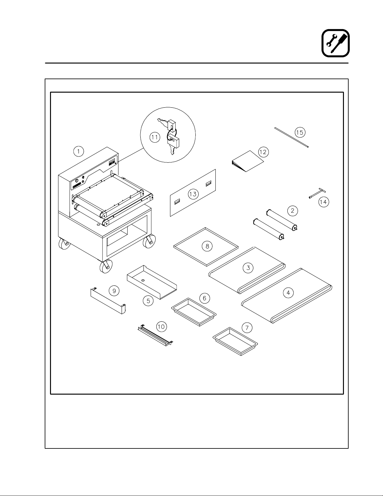
Check that all of the following parts have been re-
ceived. Contact Blodgett immediately if any of the
components are damaged or missing.
ITEM DESCRIPTION QTY.
1Blodgett Conveyor Grill, Model TBG36 (TBG36-FM shown) 1
2Idle Rollers 2
3UpperConveyorBelt 2
4LowerConveyorBelt 2
5Drain Pan 1
6Product Receiving Pan 1
7Grease Pan / Bucket 1
8Crumb Tray 1
9Upper Wiper Box 1
10 Lower Wiper Box 1
11 Controller Programming Keys 2
12 Owner’s Manual 1
13 Door Panel (FM and S models only) 1
14 9/16” Tee Handle Wrench 1
15 1/2” Calibration Rod 1
Items not
h
Wiper Blades 2
shown Bacon Scraper Blade 1

Installation
5
Delivery and Inspection
TBG36-FM floor model shown, TBG36-CM counter model has legs in place of the base with casters,
TBG36-S has two platen sets for cooking on a single base with casters (quantities of all parts are doubled for TBG36-S models)
Figure 2

117F LISTED
COMMERCIAL COOKING APPLIANCE
TBG36-S not currently listed in Canada
Installation
6
Agency Approvals
THE INSTALLATION INSTRUCTIONS CON-
TAINED HEREIN ARE FOR THE USE OF QUALI-
FIED INSTALLATION AND SERVICE PERSONNEL
ONLY. INSTALLATION OR SERVICE BY OTHER
THAN QUALIFIED PERSONNEL MAY RESULT IN
DAMAGE TO THE OVEN AND/OR INJURY TO
THE OPERATOR.
Qualified installation personnel are individuals, a
firm, a corporation, or a company which either in
person or through a representative are engaged
in, and responsible for:
D
the installation of electrical wiring from the elec-
tric meter, main control box or service outlet to
the electric appliance.
Qualified installation personnel must be experi-
enced in such work, familiar with all precautions
required, and have complied with all requirements
of state, national and/or local authorities having ju-
risdiction.
U.S. and Canadian installations
The unit must be wired in compliance with ANSI/
NFPA 70 NEC(the National Electrical Code) and
all local codes and ordinances required where the
Blodgett Conveyor Grill is installed.
General export installations
Installation must conform with Local and National
codes and installation standards. Local installa-
tion codes and/or requirements may vary. If you
have any questions regarding the proper installa-
tion and/or operation of your Blodgett Conveyor
Grill, please contact your local distributor. If you do
not have a local distributor, please call Blodgett
Technical Service at 0011-888-992-6624.

Installation
7
Grill Ventilation, Clearances and Installation Requirements
VENTILATION
While the Blodgett Conveyor Grill requires less
ventilation than a conventional griddle, a power
vented hood of at least 525 CFM capacity is re-
quired for proper performance and safety of one
TBG36.
CLEARANCES
The unit is designed for 0” clearance on the sides
and back, however, it is wise to allow more clear-
ance for ease of operation, cleaning and mainte-
nance.
INSTALLATION REQUIREMENTS
A UNIT INSTALLATION AND CALIBRATION SER-
VICE IS PROVIDED FOR AND IS REQUIRED BE-
FORE USING THE BLODGETT CONVEYOR
GRILL FOR THE FIRST TIME. UNIT INSTALLA-
TION AND CALIBRATION IS TO BE CARRIED
OUT ONLY BY SERVICE AGENTS OR PERSON-
NEL AUTHORIZED BY BLODGETT TECHNICAL
SERVICE TO PERFORM THIS WORK. IF ONE
HAS NOT YET BEEN PERFORMED ON YOUR
UNIT, CONTACT BLODGETT TECHNICAL SUP-
PORT AT 888-992-6624 TO ARRANGE FOR AN
ASAP SERVICE VISIT.
WARNING!!
DO NOT use the unit before this service
has been performed. Use of the unit prior
to this or installation or servicing by other
than Blodgett Technical Service autho-
rized service agencies or personnel may
void warranty coverage.

Installation
8
Blodgett Conveyor Grill Assembly
UPPER GREASE WIPER BOX
1. Before installing the upper grease wiper box,
slidetherubberwiperbladeintoit’sslotinthe
wiper box. Slide the long edge in first. See
Figure 3.
Wiper
Blade
Figure 3
2. Snap the four spring fingers of the upper wiper
box over the screws in the end frame. See
Figure 4. The long fingers go on top.
NOTE: The wiper box opens towards the
back to allow the grease to flow to the
rear of the unit.
Figure 4
LOWER GREASE WIPER BOX
1. Before installing the lower wiper box, insert
the rubber wiper blades into their slots in the
wiper box. See Figure 5.
Figure 5
2. Install the lower wiper box byhanging the slots
in the mounting brackets onto the screw
heads on top of the deck. See Figure 6. The
wiper box rides against the belt by its own
slung weight.
Figure 6

Installation
9
Blodgett Conveyor Grill Assembly
DRAIN PAN
1. Place the drain pan into position at the bottom
left of the unit .
OPTIONAL OUTFEED SLIDE AND RECEIVING
PAN
1. Slide the outfeed slide onto the left hand edge
of the drain pan and push it to the back. Be
sure the slot on the baffle fits tightly onto the
side of the drain pan.
2. Attach the removable shelf to the left side of
thegrillbaseandseatitfirmlyontothebase
rim.
3. Place a product receiving pan up to 4-1/2”
deep on the shelf and under the lower edge of
the slide to collect the finished foods.
Removable
Shelf
Receiving
Pan
Outfeed
Slide
Drain Pan
Figure 7
OPTIONAL INFEED SLIDE
The infeed slide option allows food product to be
loaded on a slide to feed by itself so other work
may be done while cooking.
1. Slip the infeed slide onto the lower platen rails
at the infeed end. Push until it seats fully.
Figure 8

Installation
10
Blodgett Conveyor Grill Assembly
GREASE PAN AND CRUMB TRAY
1. Place the grease pan (grease bucket for floor
models) in its compartment under the front of
the unit, making sure it is located beneath the
downspout tube of the drain trough.
2. Slide the crumb tray under the lower platen on
the right side of the unit.
3. Install the door panel on the front of the lower
compartment (TBG36-FM and TBG36-S only).
Crumb Tray
Grease Pan
Door Panel
Figure 9

Operation
11
Control Panel
THE INFORMATION CONTAINED IN THIS SEC-
TION IS PROVIDED FOR THE USE OF QUALIFIED
OPERATING PERSONNEL. QUALIFIED OPERAT-
ING PERSONNEL ARE THOSE WHO HAVE CARE-
FULLY READ THE INFORMATION CONTAINED IN
THIS MANUAL, ARE FAMILIAR WITH THE FUNC-
TIONS OF THE OVEN AND/OR HAVE HAD PRE-
VIOUS EXPERIENCE WITH THE OPERATION OF
THE EQUIPMENT DESCRIBED. ADHERENCE TO
THE PROCEDURES RECOMMENDED HEREIN
WILL ASSURE THE ACHIEVEMENT OF OPTIMUM
PERFORMANCE AND LONG, TROUBLE-FREE
SERVICE.
Please take the time to read the following operat-
ing instructions. They are the key to the successful
operation of your Blodgett Conveyor Grill.
CONTROL DESCRIPTIONS
NOTE: For TBG36-CM and TBG36-FM, refer to
Figure 10. For TBG36-S, refer to Figure 11.
1. SELECT/DISPLAY --- used to select the dis-
play information.
2. UP and DOWN ARROW --- u s e d i n p r o g r a m -
ming to increase/decrease selection choices.
3. ENTER --- used to enter a menu selection into
the current program.
4. OFF/CANCEL --- cancels the current menu so
another may be entered.
5. KEYSWITCH --- requires a key to change from
MENU mode to PROGRAM mode.
6. CLEAN --- raises the upper platen for thor-
ough cleaning.
7. MENU buttons --- used in the MENU mode to
load programming for products A through F.
Used in PROGRAM mode to select menu des-
ignations and product descriptions.
8. DISPLAY --- displays the menu and program
mode information selected.
9. EMERGENCY LIFT --- immediately raises the
upper platen to the clean position. Push and
turn to reset/release button.
10. LIFT ENABLE --- a safety feature requiring the
operator to hold the button in while moving the
platen to a cooking position after a program-
ming adjustment or menu change.
11. MAIN POWER SWITCH --- An ON-OFF rotary
switch for emergency or convenience use
which controls all electrical power inside the
unit. When power is on, the display lights up.
TBG36-CM and TBG36-FM Control
1 2 3 4
5267
89 10
11
NEED NEW ARTWORK
Figure 10

Operation
12
Program Mode
TBG36-S Control
1
2
3
4
5
2
6
7
8
9
10
11
Figure 11
PROGRAMMING
PROGRAM mode is used to define six cooking
programs A through F. It can only be entered by
use of the keyswitch. To use the PROGRAM mode
follow the steps below:
Select Desired Menu to program:
1. Turn on the unit MAIN POWER SWITCH (11).
2. Turn the KEYSWITCH (5) to the PROGRAM
position. The display reads [PROG?A].
3. Press the letter of the desired MENU KEY (7).
4. Press ENTER (3) to select the desired menu.
NOTE: If the display reads [TBG36?], the
model size has not been selected.
Press ENTER (3) to select the 36”
model size.
Setting the Cooking Temperature
NOTE: The maximum cook temperature is 450
_
F.
The minimum cook temperature is 70
_
F.
1. The display reads [TH=xxx], indicating that the
top heater (TH=) is set for xxx_F. U s e t h e A R -
ROW (2) keys to raise or lower the temperature
setting for the upper platen.
2. Press ENTER (3) to choose that temperature
and enter it into the program.
3. The display now reads [BH=xxx], indicating that
the bottom heater (BH=) is set for xxx_F. U s e
the ARROW (2) keys to raise or lower the tem-
perature setting for the upper platen.
4. Press ENTER (3) to choose that temperature
and enter it into the program.
Setting the Cook Time
NOTE: The maximum cook time is 10:00 minutes.
The minimum cook time is 0:30 seconds.
NOTE: This is the actual cooking time (the time
spent between the upper and lower plat-
ens) not the total time to travel the length
of the lower conveyor belt.
1. The display now reads [T=xx.xx]. This indi-
cates the current cooking time is xx.xx min-
utes/seconds. Use the ARROW (2) keys to en-
ter the desired cooking time.
2. Press ENTER (3) to enter the new cooking
time into the program.

Operation
13
Program Mode
Setting the Platen Height
NOTE: The maximum platen height is 1.900”. The
minimum platen height is 0.100”.
1. The display now reads [H=x.xxx]. This indi-
cates the current distance between platens in
inches and thousandths. Use the ARROW (2)
keys to change this value.
2. Press ENTER (3) to enter the new platen
height into the program.
Setting the Product Description
If you do not want to change the product descrip-
tion:
1. Press SELECT DISPLAY (1) followed by EN-
TER to save the program.
To change the product description:
1. If the display now reads [CHICKEN],thisisthe
product description for the menu you are now
modifying. The text is changed one letter at a
time using the ARROW (2) keys for the letter
that is blinking.
2. Press ENTER (3) to select that character and
move onto the next letter. Move from one char-
acter to the next using the ENTER (3) key until
you reach the end.
3. You will need to blank out any unwanted/extra
letters before saving. The blank space is lo-
cated a few characters after the z.
4. Press SELECT DISPLAY (1) to select and store
the whole word (product description).
Saving the New Menu Programming
1. When your menu programming session is
complete, press ENTER (3) to save the new
program. The display reads [SAVING].
PROGRAMMING TIPS
D
Once a setting has been entered, you cannot go
back to change it during the current program-
ming session. If you make a mistake, finish pro-
gramming any desired variables and save the
program. Go back into the programming mode
for that menu, cycle through the variables with
the ENTER (3) button and correct the desired
entry. Press ENTER (3) to save the program
again.
D
Do not enter a platen height of less than 0.100”
or greater than 1.900”.
D
Do not enter cooking times (belt speeds) of less
than 30 seconds or more than 10 minutes.

Operation
14
Menu Mode
Menu mode allows the user to select one of the six
programmed product settings. To operate the unit
in the MENU mode simply follow the steps below:
Select Desired Menu to Run
1. Turn on the MAIN POWER SWITCH (11).
2. Turn the KEYSWITCH (5) to the MENU position.
3. The display reads [MENU?A].
4. Press the letter of the desired MENU (7) key.
5. Press ENTER (3) to select the desired menu
and press and hold the LIFT ENABLE (10) but-
ton until the display shows a countdown or the
menu description starts to scroll and the belts
begin to turn.
Preheat Standby
1. Once the unit has reached the programmed
height, the display will count down from 15:00
while the unit is preheating to the programmed
temperature.
2. When the platens have reached the pro-
grammed temperature the menu description
starts to scroll and the belts begin to turn.
Cooking Process
1. The unit is now ready to begin cooking and the
product may be placed on the lower belt. Be
sure the product receiving pan, grease pan and
wiper boxes are in place.
2. During the cooking process the display will
show one of the following scrolling lists:
D
Te m p e r a t u r e [ TH/BH]
D
Height
D
Cook Time
D
Product Description
Press SELECT/DISPLAY (1) to toggle through
the list.
WARNING!!
During operation, check the contents of
the grease pan regularly. Do not allow the
pan to become so full that it is awkward to
handle and empty safely.
End Selected Menu
1. Press OFF/CANCEL (4) to exit from the current
menu.
2. The display reads [T=xx:xx] (programmed
cook time). The belts will continue to move un-
til one cook cycle has finished. To exit before
the count down or cycle is complete, press
OFF/CANCEL (4) again.
Emergency Lift
1. Pushing the Emergency Lift (9) button will im-
mediately raise the upper platen deck to the
clean position. To release the Emergency Lift
button, turn it to the right as indicated by the
arrows on the button.
NOTE: If the upper platen moves down, then
right back up when it attempts to posi-
tion in MENU mode, this button is
probably pushed and locked in. This
button must be released before the
platen height can be adjusted.

Operation
15
Menu Development
Blodgett recommends setting the bottom platen
temperature 25_to 50_F lower than the top platen
setting. This results in an even browning top and
bottom. The bottom of the food items have direct
contact with the belt throughout the baking pro-
cess. The top of the food product may not have
continuous contact with the belt.
When creating menu settings, the items tested
should reach an internal temperature 25_Fhigher
than the minimum recommended temperature. This
allows for possible temperature variations under ex-
treme conditions such as colder than normal hold-
ing temperatures, improper product spacing on the
belt or a continuous load production.
It is important to check the internal product tempera-
tures on the front, middle and back rows. These in-
ternal temperatures must be monitored continuous-
ly to ensure that safety guidelines are met.
Use the troubleshooting guide below to adjust your
menu settings if necessary.
PROBLEM SUGGESTED REMEDY
SYMPTOM: Acceptable internal temperature but unacceptable results
S
Overdone tops
S
Underdone tops
S
Overdone bottoms
S
Underdone bottoms
S
Lower the top platen temperature or raise the
platen height.
S
Raise the top platen temperature or lower the
platen height.
S
Lower the bottom platen temperature.
S
Raise the bottom platen temperature.
SYMPTOM Unacceptable internal temperature
S
Internal temperature too low
S
Internal temperature too high
S
Raise the temperature or increase the cook time.
S
Lowerthetemperatureordecreasethecooktime.
SYMPTOM: Uneven browning
S
Need more browning on top of food product
S
Need less browning on top of food product
S
Need a darker bottom
S
Need a lighter bottom
S
Lower the platen height or increase the
temperatureorcooktime.
S
Raise the platen height or decrease the
temperatureorcooktime.
S
Increase the bottom platen temperature.
S
Decrease bottom platen temperature.

Operation
16
Grilling Tips
The following menus have been developed for various products and will serve as a starting point for your
menu development.
Product
Portion To p
Heat
Bottom
Heat Height Time
Qty
row
Qty
hr Comments
MEATS (settings will vary greatly depending on product thickness)
Hamburger,
frozen
10:1
(1.6 oz)
6:1
(2.7 oz)
4:1
(4 oz)
450_F
450_F
450_F
425_F
425_F
425_F
0.35”
0.43”
0.54”
1:35
2:20
3:30
3
3
3
850
500
330
For lighter burgers, lower
temp. and extend time
For lighter burgers, lower
temp. and extend time
52 seconds per ounce
Hamburger,
fresh
4:1
(4 oz)
450_F 425_F 0.48” 1:40 3 700 For lighter burgers, lower
temp. and extend time
Steak, fresh 6oz 450_F 425_F 0.73” 4:00 2 1:30
Pork Rib Cutlets,
boneless,
cooked
6:1
(2.7 oz)
450_F 425_F 0.50” 1:45 3 530
Minute Steak,
frozen
2 450_F 425_F 0.24” 1:00 3 440 Adjust height to obtain
desired browning
Bacon Strips,
fresh
sliced 450_F 425_F 0.15” 0:45 8-10 1840-
2300
Adjust height to obtain
desired browning
Bacon Strips,
frozen
sliced 450_F 425_F 1.15” 0:55 8-10 1500-
1800
Adjust height to obtain
desired browning
POULTRY (settings will vary greatly depending on product thickness)
Chicken Breast,
fresh boneless
5oz 450_F 425_F 0.75” 4:00 3 200 G o l d e n b r o w n ---
48 seconds per oz
Chicken Patties,
cooked,
breaded, frozen
2.5 oz 450_F 425_F 0.70” 5:30 3 210 G o l d e n b r o w n ---
48 seconds per oz
Chicken Fingers,
cooked,
breaded
450_F 425_F 0.58” 3:50 8 810 G o l d e n b r o w n ---
48 seconds per oz
This manual suits for next models
2
Table of contents
Other Blodgett Grill manuals
Popular Grill manuals by other brands

Ninja
Ninja WOODFIRE OG701UK user manual

TM Electron
TM Electron TMPGR010 instruction manual

King Kooker
King Kooker cast cooker With timer Assembly instructions and use and care manual

Char-Broil
Char-Broil Quickset 4638220 Assembly, use and care manual

DKB
DKB HEAT CUBE 45 owner's manual

Neumaerker
Neumaerker E-6P operating manual