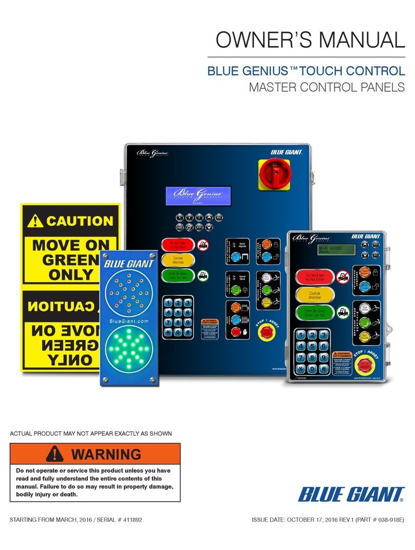
Blue Giant Blue Genius Touch Control User manual

ACTUAL PRODUCT MAY NOT APPEAR EXACTLY AS SHOWN
STARTING FROM NOVEMBER 4, 2021 / SERIAL # 0.0 ISSUE DATE: SEPTEMBER 6, 2022 REV.1.0 (PART # 038-918EI)
BLUE GENIUS™TOUCH CONTROL
MASTER CONTROL PANELS
INSTALLATION MANUAL
WARNING
Do not operate or service this product unless you have
read and fully understand the entire contents of this
manual. Failure to do so may result in bodily injury or
death.


BLUE GENIUS™ TOUCH CONTROL MASTER CONTROL PANELS—INSTALLATION MANUAL
3ISSUE DATE: SEPTEMBER 6, 2022 REV.1.0 (PART # 038-918EI)
Table of Contents
Table of Contents
1.0 INTRODUCTION 5
1.0 INTRODUCTION 5
1.1 WARRANTY INFORMATION 5
1.1 WARRANTY INFORMATION 5
1.2 EXCLUSION OF LIABILITY 5
1.2 EXCLUSION OF LIABILITY 5
1.3 MANUFACTURER’S NOTE 6
1.3 MANUFACTURER’S NOTE 6
1.4 INSTALLER’S GUIDELINES 6
1.4 INSTALLER’S GUIDELINES 6
2.0 SAFETY MESSAGE COLOR IDENTIFICATION 7
2.0 SAFETY MESSAGE COLOR IDENTIFICATION 7
2.1 OPERATIONAL SAFETY WARNINGS 7
2.1 OPERATIONAL SAFETY WARNINGS 7
3.0 LOCKOUT / TAGOUT PROCEDURE AND RULES 9
3.0 LOCKOUT / TAGOUT PROCEDURE AND RULES 9
3.1 ROTARY DISCONNECT: PLATINUM SERIES 9
3.1 ROTARY DISCONNECT: PLATINUM SERIES 9
3.2 ELECTROSTATIC SENSITIVE DEVICE PROTECTION POLICY 10
3.2 ELECTROSTATIC SENSITIVE DEVICE PROTECTION POLICY 10
STAGE 1. COMPONENTS 11
STAGE 1. COMPONENTS 11
1.1 PRE-INSTALLATION VERIFICATIONS 11
1.1 PRE-INSTALLATION VERIFICATIONS 11
1.2 COMPONENTS AS SHIPPED CHECKLIST 13
1.2 COMPONENTS AS SHIPPED CHECKLIST 13
1.3 COMPONENTS AS SHIPPED CHECK LIST: GOLD SERIES III 13
1.3 COMPONENTS AS SHIPPED CHECK LIST: GOLD SERIES III 13
1.4 EQUIPMENT COMPONENT ILLUSTRATIONS: PLATINUM SERIES 14
1.4 EQUIPMENT COMPONENT ILLUSTRATIONS: PLATINUM SERIES 14
1.5 GENERAL DESCRIPTION 15
1.5 GENERAL DESCRIPTION 15
1.6 GENERAL DIMENSIONS: GOLD SERIES III 15
1.6 GENERAL DIMENSIONS: GOLD SERIES III 15
1.7 GENERAL DIMENSIONS: PLATINUM SERIES 16
1.7 GENERAL DIMENSIONS: PLATINUM SERIES 16
1.8 TOOLS FOR INSTALLATION 17
1.8 TOOLS FOR INSTALLATION 17
STAGE 2. LAYOUT OPTIONS 18
STAGE 2. LAYOUT OPTIONS 18
2.1 WALL MOUNT 18
2.1 WALL MOUNT 18
2.2 PEDESTAL MOUNT 19
2.2 PEDESTAL MOUNT 19
STAGE 3. WALL MOUNT 20
STAGE 3. WALL MOUNT 20
3.1 CONTROL PANEL INSTALLATION 20
3.1 CONTROL PANEL INSTALLATION 20
3.2 WALL MOUNT 20
3.2 WALL MOUNT 20
3.3 GOLD CONTROL UNIT 20
3.3 GOLD CONTROL UNIT 20
3.4 PLATINUM CONTROL UNIT 21
3.4 PLATINUM CONTROL UNIT 21
3.5 CONDUIT INSTALLATION 23
3.5 CONDUIT INSTALLATION 23
3.6 CONTROL PANEL CONDUIT 23
3.6 CONTROL PANEL CONDUIT 23
3.7 ELECTRICAL WIRING INSTALLATION 23
3.7 ELECTRICAL WIRING INSTALLATION 23
STAGE 4. PEDESTAL MOUNT 26
STAGE 4. PEDESTAL MOUNT 26
4.1 CONTROL PANEL INSTALLATION 26
4.1 CONTROL PANEL INSTALLATION 26
4.2 PEDESTAL MOUNT CONTROL PANEL 26
4.2 PEDESTAL MOUNT CONTROL PANEL 26
4.3 GOLD CONTROL PANEL 26
4.3 GOLD CONTROL PANEL 26
4.4 PLATINUM CONTROL PANEL 27
4.4 PLATINUM CONTROL PANEL 27
4.5 CONDUIT INSTALLATION 29
4.5 CONDUIT INSTALLATION 29
4.6 CONTROL PANEL CONDUIT 29
4.6 CONTROL PANEL CONDUIT 29
4.7 ELECTRICAL WIRING INSTALLATION 29
4.7 ELECTRICAL WIRING INSTALLATION 29
STAGE 5. VERIFICATIONS 32
STAGE 5. VERIFICATIONS 32
5.1 POST-INSTALLATION INSPECTION CHECKLIST 32
5.1 POST-INSTALLATION INSPECTION CHECKLIST 32
5.2 COMMISSIONING AND START-UP PROCEDURES 32
5.2 COMMISSIONING AND START-UP PROCEDURES 32
5.3 BLUE GENIUS™ LCD MESSAGES 33
5.3 BLUE GENIUS™ LCD MESSAGES 33
5.4 EXTERIOR DRIVER TRAFFIC LIGHT INSTALLATION (OPTION) 34
5.4 EXTERIOR DRIVER TRAFFIC LIGHT INSTALLATION (OPTION) 34

BLUE GENIUS™ TOUCH CONTROL MASTER CONTROL PANELS—INSTALLATION MANUAL
4 ISSUE DATE: SEPTEMBER 6, 2022 REV.1.0 (PART # 038-918EI)
5.5 EXTERIOR DRIVER WARNING SIGN INSTALLATION (OPTION) 35
5.5 EXTERIOR DRIVER WARNING SIGN INSTALLATION (OPTION) 35
5.6 DOCK PERIPHERALS 36
5.6 DOCK PERIPHERALS 36
STAGE 6. 38
STAGE 6. 38
6.1 WIRING DIAGRAMS: GOLD SERIES III AND PLATINUM SERIES 38
6.1 WIRING DIAGRAMS: GOLD SERIES III AND PLATINUM SERIES 38
6.2 230V SINGLE PHASE: GOLD SERIES III (TL85 REMOTE & FH COMBO) 39
6.2 230V SINGLE PHASE: GOLD SERIES III (TL85 REMOTE & FH COMBO) 39
6.3 230 - 575V THREE PHASE: PLATINUM SERIES* (SVR303 & VL COMBO) 40
6.3 230 - 575V THREE PHASE: PLATINUM SERIES* (SVR303 & VL COMBO) 40
6.4 230 - 575V THREE PHASE: PLATINUM SERIES (SVR303 & VL COMBO) 42
6.4 230 - 575V THREE PHASE: PLATINUM SERIES (SVR303 & VL COMBO) 42

1.0
1.0
INTRODUCTION
INTRODUCTION
The following is a quick reference to important procedures that must be followed while using the Control Panel. It is not intended to cover, or
suggest that it does cover, all procedures necessary to ensure safe operation. All operators should be aware of and abide by all workplace
safety regulations applicable to the operation of the Control Panel . These laws and regulations include but are not limited to:
• The Occupational Safety and Health Act
• Canada Occupational Health and Safety Regulations
• Occupational Safety and Health Acts for Individual States (USA), Provinces, or Territories.
For additional information on these regulations as well as industry standards that may apply to this product, please contact:
American National Standards Institute (ANSI)
1430 Broadway
New York, NY 10018
Telephone: 212.642.4900
www.ansi.org
Loading Dock Equipment Manufacturers
A Product Section of Material Handling Industry of America
A Division of Material Handling Industry
8720 Red Oak Blvd, Suite 201
Charlotte, NC, 28217-3992
Telephone: (704) 676-1190
www.mhi.org/lodem
1.1
1.1
WARRANTY INFORMATION
WARRANTY INFORMATION
Thank you for purchasing Blue Giant products. We appreciate your business, and are confident that our product will serve you for many
years to come. In the event that you experience a problem with our product, our Customer Support Team is here to support the
Blue Giant Product(s) that you have purchased.
To validate warranty on recently purchased equipment, please complete and submit your information with our on-line
Warranty Registration at www.BlueGiant.com.
For more information about Blue Giant Warranty Support, please contact your Blue Giant Dealer. You may also visit www.BlueGiant.com or
phone 1.905.457.3900.
NOTE: All products must be registered to qualify for warranty.
DEALER INFORMATION
Name:
Contact:
Telephone:
1.2
1.2
EXCLUSION OF LIABILITY
EXCLUSION OF LIABILITY
The manufacturer assumes no liability for damage or injury to persons or property which occur as a result of defects or faults in or incorrect
use of the Control Panel. The manufacturer assumes no liability for lost profits, operating downtimes, or similar indirect losses incurred by
the purchaser. Injury to third parties, irrespective of its nature, is not subject to compensation.
BLUE GENIUS™ TOUCH CONTROL MASTER CONTROL PANELS—INSTALLATION MANUAL
5ISSUE DATE: SEPTEMBER 6, 2022 REV.1.0 (PART # 038-918EI)

The manufacturer reserves the right to make changes at any time to the modules, components, and accessories, concurrent with its
continuing product improvements and development program. Specifications, operating instructions, and illustrations included in this
manual are subject to change without notice. Please contact manufacturer for the latest information.
1.3
1.3
MANUFACTURER’S NOTE
MANUFACTURER’S NOTE
The Control Panel has been carefully inspected and tested at the manufacturer’s plant prior to shipment, but MUST be checked upon
receipt for transport damage. Any observed transport damage is to be listed on the signed copy of the freight document.
There are many configurations or custom designs whose specifications may not be fully reflected in this manual. Contact your Blue Giant
Dealer to obtain the General Arrangement drawing for application specific designs.
Notify the freight forwarder, Blue Giant, and the dealer of any damage WITHIN 24 HOURS.
1.4
1.4
INSTALLER’S GUIDELINES
INSTALLER’S GUIDELINES
Please read all instructions carefully before installing this Blue Giant dock product. It is the installer’s responsibility to comply with the
following:
• The installation of Blue Giant dock products should comply with all applicable local or national building codes and regulations,
including any that may supersede this manual.
• Site surveys and other applicable install-related documentation must be properly and accurately completed prior to installation.
Failure to comply with this requirement may result in an improper install and possible voiding of the warranty.
Only Blue Giant-supplied or approved parts must be used. Any unauthorized parts substitution may void the warranty. Always lock out and
tag out any power source before performing any electrical work, in accordance with OSHA regulations and approved electrical codes. The
installer is responsible for reading, understanding, and complying with all personal protective equipment (PPE) policies in effect.
BLUE GENIUS™ TOUCH CONTROL MASTER CONTROL PANELS—INSTALLATION MANUAL
6 ISSUE DATE: SEPTEMBER 6, 2022 REV.1.0 (PART # 038-918EI)

2.0
2.0
SAFETY MESSAGE COLOR IDENTIFICATION
SAFETY MESSAGE COLOR IDENTIFICATION
This manual includes color-coded safety messages that clarify instructions and specify areas where potential hazard exists. To reduce
the possibility of equipment damage and serious injury or death, please follow the instructions and understand the warnings contained
in the messages. If warning decals become damaged or missing, replace them immediately. Avoid accidents by recognizing dangerous
procedures or situations before they occur.
DANGER
Serious injury or death will likely occur if the instructions are not followed.
WARNING
Serious injury or death may occur if the instructions are not followed.
CAUTION
Instructions marked caution concern safe operating procedure. Failure to comply may result in personal injury.
NOTICE
Procedures marked notice must be followed in order to reduce damage to machinery.
2.1
2.1
OPERATIONAL SAFETY WARNINGS
OPERATIONAL SAFETY WARNINGS
These are safety warnings that may be part of a procedure or hardware warning decal.
DANGER
• BEFORE BEGINNING ANY SERVICE PROCEDURES:
– Disconnect the power and follow all lockout / tagout procedures, as per OSHA requirements. Refer to wiring diagrams.
• Installation must be performed only by trained and authorized personnel.
• Prior to installation, place adequate barriers to prevent vehicle traffic from entering the work area.
• During installation, anchors must be properly torqued to achieve the necessary anchoring strength. DO NOT USE IMPACT
DRIVERS.
• Any electrical work must be performed by qualified personnel only.
• Do not remove the wheel chocks until loading / unloading is finished and the truck is cleared for departure and the lights have
changed to RED inside and GREEN outside.
WARNING
• Do not ground welding equipment to any electrical components.
• Do not allow the drill to go too deeply into the control box, as damage may occur to the control systems.
• Never use air to blow debris from the control box. Use a vacuum to perform any necessary cleaning.
• Do not connect green ground lead into control box or junction box until all welding has been completed.
• Improper adjustments may cause operational problems with equipment.
CAUTION
• Only trained personnel should operate or service this equipment.
• Do not operate the Control Panel until the transport vehicle is parked against the dock bumpers.
• Always park the Control Panel after use.
• Conduct routine inspections and maintenance. Failure to do so could cause equipment damage and or personal injury.
• Always call your authorized service representative or manufacturer immediately if a malfunction occurs.
BLUE GENIUS™ TOUCH CONTROL MASTER CONTROL PANELS—INSTALLATION MANUAL
7ISSUE DATE: SEPTEMBER 6, 2022 REV.1.0 (PART # 038-918EI)

NOTICE
• Do not ground welding equipment to any electrical components.
• Do not allow the drill to go too deeply when drilling holes in the control panel. Damage to the control systems may occur.
• Never use air to blow debris from control box. Use a vacuum to remove debris from control box.
• Do not connect green ground lead into control box until all welding has been completed.
• Always keep the work area clean and free of litter.
• Always clean all side openings of dirt and debris.
• Always clean up dry and liquid spills immediately after they occur.
• Always maintain proper lighting in the work area.
• If a procedure is not clearly defined in this manual, contact your Blue Giant Dealer.
BLUE GENIUS™ TOUCH CONTROL MASTER CONTROL PANELS—INSTALLATION MANUAL
8 ISSUE DATE: SEPTEMBER 6, 2022 REV.1.0 (PART # 038-918EI)

3.0
3.0
LOCKOUT / TAGOUT PROCEDURE AND RULES
LOCKOUT / TAGOUT PROCEDURE AND RULES
In accordance with the rules and regulations of the Occupational Safety and Health Administration (OSHA) and/or local jurisdiction, all
affected employees must be notified that the machine or equipment will be shut down and locked out to perform repair or maintenance
work.
The work area must be checked to verify that all personnel have been removed or safely repositioned.
The machine or equipment power supply shall be locked in the OFF position or disconnected from the energy source.
Blue Giant strongly recommends that only OSHA-approved and/or local jurisdiction lockout devices and procedures be utilized.
The energy isolating device must bear a prominent warning tag indicating that work is being done on the equipment and the name of the
authorized employee responsible for the lockout.
It is mandatory that tagout notices shall NOT be susceptible to deterioration or illegibility due to weather conditions, exposure to chemicals
and/or moisture.
WARNING
Always lockout and tagout any power source before performing any work on any electrical devices or electrical controls according to
OSHA regulations and approved local electrical codes. Refer to wiring diagrams.
An example of lockout / tagout. Verify and comply with local codes/regulatory requirements.
3.1
3.1
ROTARY DISCONNECT: PLATINUM SERIES
ROTARY DISCONNECT: PLATINUM SERIES
The Platinum Series has a built-in rotary disconnect. The disconnect has two switch positions: ON and OFF, and can be locked in either
position.
XXXXXXXXXXXX
XXXXXXXXXXX
OPERATE
DO NOT
This Lock/Tag may
only be removed by:
OPERATE
DO NOT
BLUE GENIUS™ TOUCH CONTROL MASTER CONTROL PANELS—INSTALLATION MANUAL
9ISSUE DATE: SEPTEMBER 6, 2022 REV.1.0 (PART # 038-918EI)

3.2
3.2
ELECTROSTATIC SENSITIVE DEVICE PROTECTION POLICY
ELECTROSTATIC SENSITIVE DEVICE PROTECTION POLICY
This policy applies to static sensitive electronic products primarily printed circuit boards (PCBs) and sensors. Switches, relay, lamps, and
wire are not sensitive and do not apply.
If welding near ESD components, correctly protect and ground all necessary equipment.
1. Prior to handling PCBs, wear a static grounding wrist strap and clip it to an electrical ground. The metal plate on the inside of the
wristband must be in contact with the wearers skin.
2. PCBs should never be handed to other personnel or set down anywhere.
3. Place PCBs in black ESD shielding bags for return or storage. Only one PCB or sensor should be placed in a static bag. Attach
paperwork and other items to the outside with adhesive pouches or elastic bands.
4. The control boxes protect the PCBs inside from static, and should not be used to store manuals or other accessories.
ATTENTION
DO NOT DISCARD. Any components shipped
back to Blue Giant must be in their original
packaging (along with completed RGA form
taped to the OUTSIDE of the static bag) or
warranty may be voided.
OBSERVE PRECAUTIONS
FOR HANDLING
ELECTROSTATIC
SENSITIVE DEVICES
038-850E
BLUE GENIUS™ TOUCH CONTROL MASTER CONTROL PANELS—INSTALLATION MANUAL
10 ISSUE DATE: SEPTEMBER 6, 2022 REV.1.0 (PART # 038-918EI)

STAGE 1. COMPONENTS
1.1 PRE-INSTALLATION VERIFICATIONS
Use this chart to prepare the site for installation.
NOTE: If any of the these questions are answered by NO then consult submittal drawings and arrange the correction BEFORE
resuming the installation.
CAUTION
• Use caution when lifting or moving the Blue Genius Control Panel, the cables, and the mounting equipment.
Yes No Comments
1 Review site conditions. Have you completed and reviewed
site survey report? FF
2 Is there enough room to mount the control panel? FF
3
Do the environmental conditions match the specifications on
the site assessment/drawings? FF
4
Is the facility ready to have the control panel equipment
installed? FF
5
Is the electrical power present for hook up?
i.e. on inside wall near control install location FF
6
Are the proper fused voltage and amperage supplied?
Check the Blue Giant Website for amperages based on
equipment. See 038-899E. FF
7 If required, was the conduit(s) installed and properly
positioned? (embeded conduit or surface mounted conduit) FF
8
When unpacking, were all the parts included?
See “1.2 COMPONENTS AS SHIPPED CHECKLIST” on
page 13. FF
9
Are the products and equipment in good condition and
ready for use? FF
10
Do you have all the tools needed to complete the job? This
includes ladder(s), safety equipment and personal safety
devices. See “6.0 TOOLS REQUIRED FOR INSTALLATION”
on page 13.
FF
11
Do you have the anchors for the (optional) exterior driver
traffic light, warning sign and control box? Supplied by:
You, contractor, or installer FF
BLUE GENIUS™ TOUCH CONTROL MASTER CONTROL PANELS—INSTALLATION MANUAL
11ISSUE DATE: SEPTEMBER 6, 2022 REV.1.0 (PART # 038-918EI)

Yes No Comments
12 Are the walls, stanchion, or pedestals ready for anchoring? FF
13 Have you read this installation manual and fully understood
it? FF
14
Do you have the Blue Giant technical support number?
1.800.872.2583. Before calling, make sure to have the serial
# of the equipment.
FF
15
Do you know what an ESD "Electrostatic Sensitive
Device" is and how to handle? See “4.1 ELECTROSTATIC
SENSITIVE DEVICE PROTECTION POLICY” on page 11. FF
16 Are all conditions met, as listed in the submittal documents
and this table? FF
GENERIC OVERVIEW
This illustration shows the Isometric view of a possible wall installation.
20"
(508 mm)
14"
(356 mm)
COMMUNICATION CABLES
CONTROL CABLES, LOW VOLTAGE
POWER/MOTOR WIRING, HIGH VOLTAGE
HYDRAULIC HOSE LINES
84" typ.
(2134 mm)
66" typ.
(1676 mm)
ISO View
BLUE GENIUS™ TOUCH CONTROL MASTER CONTROL PANELS—INSTALLATION MANUAL
12 ISSUE DATE: SEPTEMBER 6, 2022 REV.1.0 (PART # 038-918EI)

1.2 COMPONENTS AS SHIPPED CHECKLIST
This section displays the shipped hardware components.
1.3 COMPONENTS AS SHIPPED CHECK LIST: GOLD SERIES III
√ITEM QTY PART NO. DESCRIPTION APPROX. WEIGHT
11
Dependent on voltage
See Section 7.2 Blue Genius™ Gold Series III Control Panel 10 lb 4.5 kg
2 1 025-G010-1 Mounting Tabs with hardware (1 pkg. of 4) — —
3 1 038-225
E
Exterior Driver Warning Sign 0.7 lb 0.32 kg
F
S
P
4 1 032-806 Exterior Driver Traffic Light 1.3 lb 0.6 kg
5 1 038-918
E
Owner's Manual — —
F
S
6 1 038-918
EI
Installation Manual — —
FI
7 1 038-918
EPL
Parts List — —
FPL
8 1 Dependent on model #
E
Operation Placard(s) — —F
S
OWNER’S MANUAL
BLUE GENIUS™TOUCH CONTROL
MASTER CONTROL PANELS
ISSUE DATE:JULY 15, 2020 REV.1.1 (PART# 038-918E)STARTINGFROM MARCH, 2016 / SERIAL # 411892
WARNING
ACTUAL PRODUCT MAYNOT APPEAR EXACTLY AS SHOWN
Do not operate or service this product unless you have
read and fully understand the entire contents of this
manual. Failure to do so may result in property damage,
bodily injury or death.
CONTROL AND
COMPONENTS
1
2
5
3
467
8
BLUE GENIUS™ TOUCH CONTROL MASTER CONTROL PANELS—INSTALLATION MANUAL
13ISSUE DATE: SEPTEMBER 6, 2022 REV.1.0 (PART # 038-918EI)

1.4 EQUIPMENT COMPONENT ILLUSTRATIONS: PLATINUM SERIES
OWNER’S MANUAL
BLUE GENIUS™TOUCH CONTROL
MASTER CONTROL PANELS
ISSUE DATE:JULY 15, 2020 REV.1.1 (PART# 038-918E)STARTINGFROM MARCH, 2016 / SERIAL # 411892
WARNING
ACTUAL PRODUCT MAYNOT APPEAR EXACTLY AS SHOWN
Do not operate or service this product unless you have
read and fully understand the entire contents of this
manual. Failure to do so may result in property damage,
bodily injury or death.
123
4
5
6
CONTROL AND
COMPONENTS
7
8
√ITEM QTY PART NO. DESCRIPTION APPROX. WEIGHT
11
BGP-4-XXXXX-X
Dependent on voltage
See Section 10.2
Blue Genius™ Platinum Series Control Panel 25 - 35 lb 11 - 16 kg
2 1 025-G012-1 Mounting Tabs with Hardware (1 pkg. of 4) — —
3 1 038-225
E
Exterior Driver Warning Sign 0.7 lb 0.32 kg
F
S
P
4 1 032-806 Exterior Driver Traffic Light 1.3 lb 0.6 kg
5 1 038-918
E
Owner's Manual — —
F
S
6 1 038-918
EI
Installation Manual — —
FI
7 1 038-918
EPL
Parts List — —
FPL
8 1 Dependent on model #
E
Operation Placard(s) — —
F
S
BLUE GENIUS™ TOUCH CONTROL MASTER CONTROL PANELS—INSTALLATION MANUAL
14 ISSUE DATE: SEPTEMBER 6, 2022 REV.1.0 (PART # 038-918EI)

1.5 GENERAL DESCRIPTION
See below for names of components. These names will be used throughout the manual.
WARNING
• Do not install, operate, or service this product unless you have read and followed the safety practices, warnings, and installation
instructions contained in this manual and owner’s manual. Failure to do so could result in death or serious injury.
• Place barricades around the pit on the dock floor and driveway while installing, maintaining, or repairing dock equipment.
• Improper installation of anchoring devices or installation into aged or unsound concrete could result in death or serious injury.
1.6 GENERAL DIMENSIONS: GOLD SERIES III
8 1/32"
(204mm)
11 29/32"
(302mm)
12 17/32"
(318mm)
Ø 1/4"
Slot typ.
6 5/32"
(156mm)
Ø 3/16"
typ.
7 15/32"
(190mm)
5 13/32"
(137mm)
11 9/32"
(287mm)
10 19/32"
(269mm)
13"
(330mm)
5 27/32"
(148mm)
R= 7 15/32"
(190mm)
BLUE GENIUS™ TOUCH CONTROL MASTER CONTROL PANELS—INSTALLATION MANUAL
15ISSUE DATE: SEPTEMBER 6, 2022 REV.1.0 (PART # 038-918EI)

1.7 GENERAL DIMENSIONS: PLATINUM SERIES
STOP
ARRÊT
123
456
789
0#
*
ESC
SELA B C
R
e
Touc h Control
23 1/2"
(594mm)
9 7/16"
(239mm)
21 1/16"
(535mm)
7 13/16"
(199mm)
8 15/16"
(227mm)
4 5/8"
(117mm)
15 11/16"
(398mm)
19 5/8"
(498mm)
24 1/16"
(611mm)
R = 15 11/16"
(398mm)
3 3/4"
(96mm) 2"
(52mm)
23 1/2"
(594mm)
9 7/16"
(239mm)
21 1/16"
(535mm)
7 13/16"
(199mm)
8 15/16"
(227mm)
4 5/8"
(117mm)
15 11/16"
(398mm)
19 5/8"
(498mm)
24 1/16"
(611mm)
R = 15 11/16"
(398mm)
3 3/4"
(96mm) 2"
(52mm)
BLUE GENIUS™ TOUCH CONTROL MASTER CONTROL PANELS—INSTALLATION MANUAL
16 ISSUE DATE: SEPTEMBER 6, 2022 REV.1.0 (PART # 038-918EI)

1.8 TOOLS FOR INSTALLATION
These tools are required for the complete and safe installation of the Interlock Chock. Not all are applicable for every installation.
Multi-Purpose Hammer Drill Tape Measure Combination Wrench Set 3/8” to 1”
5/16” and ¼” Concrete Bit Carbide 2’ Level Socket Set 3/8” to 1”
Electrician’s Tools
Large 1/8” x 3/8” Screwdriver
(flat tip)
Small Flat Screwdriver
(flat tip to be suitable for .150” hole) Step Drill Bit
BLUE GENIUS™ TOUCH CONTROL MASTER CONTROL PANELS—INSTALLATION MANUAL
17ISSUE DATE: SEPTEMBER 6, 2022 REV.1.0 (PART # 038-918EI)

STAGE 2. LAYOUT OPTIONS
The facility environment will dictate the type of wall or pedestal layout. These illustrations are generic in layout. Refer to drawings for site
specific requirements. Each mounting option has separate sections for Control Panel and conduits. Refer to mounting methods in the
Stage 2.1 and 2.2.
NOTE: Blue Genius Control Panel installation may vary.
2.1 WALL MOUNT
NOTE: Illustration given as an example only.
Proceed to”STAGE 3. WALL MOUNT” on page 20
20"
(508 mm)
14"
(356 mm)
COMMUNICATION CABLES
CONTROL CABLES, LOW VOLTAGE
POWER/MOTOR WIRING, HIGH VOLTAGE
HYDRAULIC HOSE LINES
84" typ.
(2134 mm)
66" typ.
(1676 mm)
ISO View
84" (2134 mm) Light TYP.
105" (2667 mm) Sign TYP.
Front Elevation View
* Drawings not to scale
PlatinumSeries www.BlueGiant.com#038-400EF
COUPERLECOURANT
AVANTD'OUVRIR.
LIREETBIENCOMPRENDRELE
GUIDED'UTILISATIONAVANT
D'UTILISERCEPRODUIT.
READANDFULLY
UNDERSTANDTHEOWNER’S
MANUALBEFOREOPERATING
THISPRODUCT.
DISCONNECTPOWER
BEFOREOPENING.
WARNING
AVERTISSEMENT
STOP
ARRÊT
Open
Ouvrir
Close
Fermer
STOP
ARRÊT
Down
Descendre
Lèvre
Lip
Deck
Rampe
Allumée
Éteinte
Light
Lampe
On
Off
Engage
Engager
Release
Dégager
On
Off
Gonfler
Dégonfler
Seal
Sac
*
*
EnterOn Green
EntrerSur Vert
Caution
Attention
DoNot Enter
NePas Entrer
ESC
SELA BC
R
e
Touch Control
66" typ.
(1676 mm)
MAIN POWER
(from fused
disconnect)
MOTOR
INPUTS
OUTPUTS
TRAFFIC
LIGHTS
Refer to Isometric View
Front Elevation View
Mount 66" (1676 mm)
from floor to top of
control box
NOTE:
All conduit entry into control panel
from bottom. Arrange wiring to avoid
high and low voltage crossing over
inside control panel.
DO NOT: Drill holes in top
of control panel box.
Inside Building View
MAIN
POWER
(from fused
disconnect
by others)
BLUE GENIUS™ TOUCH CONTROL MASTER CONTROL PANELS—INSTALLATION MANUAL
18 ISSUE DATE: SEPTEMBER 6, 2022 REV.1.0 (PART # 038-918EI)

2.2 PEDESTAL MOUNT
NOTE: Illustration given as an example only.
Proceed to “STAGE 4. PEDESTAL MOUNT” on page 26.
COMMUNICATION CABLES
CONTROL CABLES, LOW VOLTAGE
POWER/MOTOR WIRING, HIGH VOLTAGE
HYDRAULIC HOSE LINES
84" typ.
(2134 mm)
66" typ.
(1676 mm)
ISO View
84" (2134 mm) Light TYP.
105" (2667 mm) Sign TYP.
Front Elevation View
66"
(1676 mm)
MOTOR WIRING
(to powerpack)
Refer to Isometric View
Fused
Disconnect
(fused and
sourced by others)
TRAFFIC LIGHT CABLE
(to outside wall)
BLUE GENIUS™
CONTROL PANEL
(mounted on
driver side)
Mount 66" (1676 mm)
from floor to top of
control box
NOTE:
All conduit entry into control
panel from bottom. Arrange
wiring to avoid high and low
voltage crossing over inside
control panel.
DO NOT: Drill holes in top
of control panel box.
Inside Building View
BLUE GENIUS™ TOUCH CONTROL MASTER CONTROL PANELS—INSTALLATION MANUAL
19ISSUE DATE: SEPTEMBER 6, 2022 REV.1.0 (PART # 038-918EI)

STAGE 3. WALL MOUNT
3.1 CONTROL PANEL INSTALLATION
This section describes the Control Panel wall mounting. Refer to either “3.3 GOLD CONTROL UNIT” on page 20 or “3.4 PLATINUM
CONTROL UNIT” on page 21.
NOTICE
The use of ESD protocol is now needed when handling any controls mentioned hereafter.
3.2 WALL MOUNT
A wall mount is the more common type for the Blue Genius Control Panel.
1. Mount the Control Panel on a flat surface. If the wall is uneven, shim to suit.
NOTE: Mounting on right hand side is acceptable. However, these instructions are for left hand side only.
3.3 GOLD CONTROL UNIT
1. Remove the Control Panel from the shipping box.
2. Install the wall-mounting tabs on the back of the control panel.
The mounting brackets must be installed to suit site / wall conditions.
66"
(1676 mm)
Mount the Control Panel
at 66" (1676 mm).
Wall-Mount
BLUE GENIUS™ TOUCH CONTROL MASTER CONTROL PANELS—INSTALLATION MANUAL
20 ISSUE DATE: SEPTEMBER 6, 2022 REV.1.0 (PART # 038-918EI)
Other manuals for Blue Genius Touch Control
1
Table of contents
Other Blue Giant Control Panel manuals
Popular Control Panel manuals by other brands

weintek
weintek cMT3108XH Series Installation instruction
Johnson Controls
Johnson Controls IFC-200 Installation procedures
ENDA
ENDA EOP4-104 Series installation instructions
DMP Electronics
DMP Electronics XR150FC Series installation guide

Notifier
Notifier AFP-3030 installation manual
Cofem
Cofem CLVR08Z manual
