Blue Giant M User manual

Issue Date: 10/01/01, Rev. 0 (Part #038-550E)
SERVICE MANUAL
Mechanical Dock Leveler
Mechanical Dock Leveler – M and FMC Group 01, Section 01, Page 1
Issue Date: 10/01/01, Rev. 0 (Part #038-550E)
MECHANICAL DOCK LEVELER
Models M and FMC
Serial Number 9840001 and Up
IMPORTANT
Read and understand Pages 1 through 4 at the beginning of this
binder before proceeding with any repair or maintenance work.
The technician is cautioned and expected to take time to completely
read and understand the first four pages of this binder, including any
special instructions contained in this Mechanical Dock Leveler
portion, to be better prepared to safely perform the necessary work
before beginning any work.
Do not work under or around the Dock Leveler without first placing
adequate barriers to positively prevent vehicle traffic from entering
the work area.
INDEX
Subject Group Section Page
Master Index 01 01 1
Introduction & Component I.D. 02 01 1 - 4
Theory of Operation – Index 03 01 1
Troubleshooting 04 01 1 - 2
Service Adjustments – Index 06 01 1
Service and Repairs – Index 08 01 1
Replacement Parts - Index 12 01 1
Installation Instructions - Index 14 01 2
Maintenance Lubrication 16 01 1 - 3
Mechanical Dock Leveler – M and FMC Group 02, Section 01, Page 1
Issue Date: 10/01/01, Rev. 0 (Part #038-550E)
INTRODUCTION
Mechanical Dock Leveler
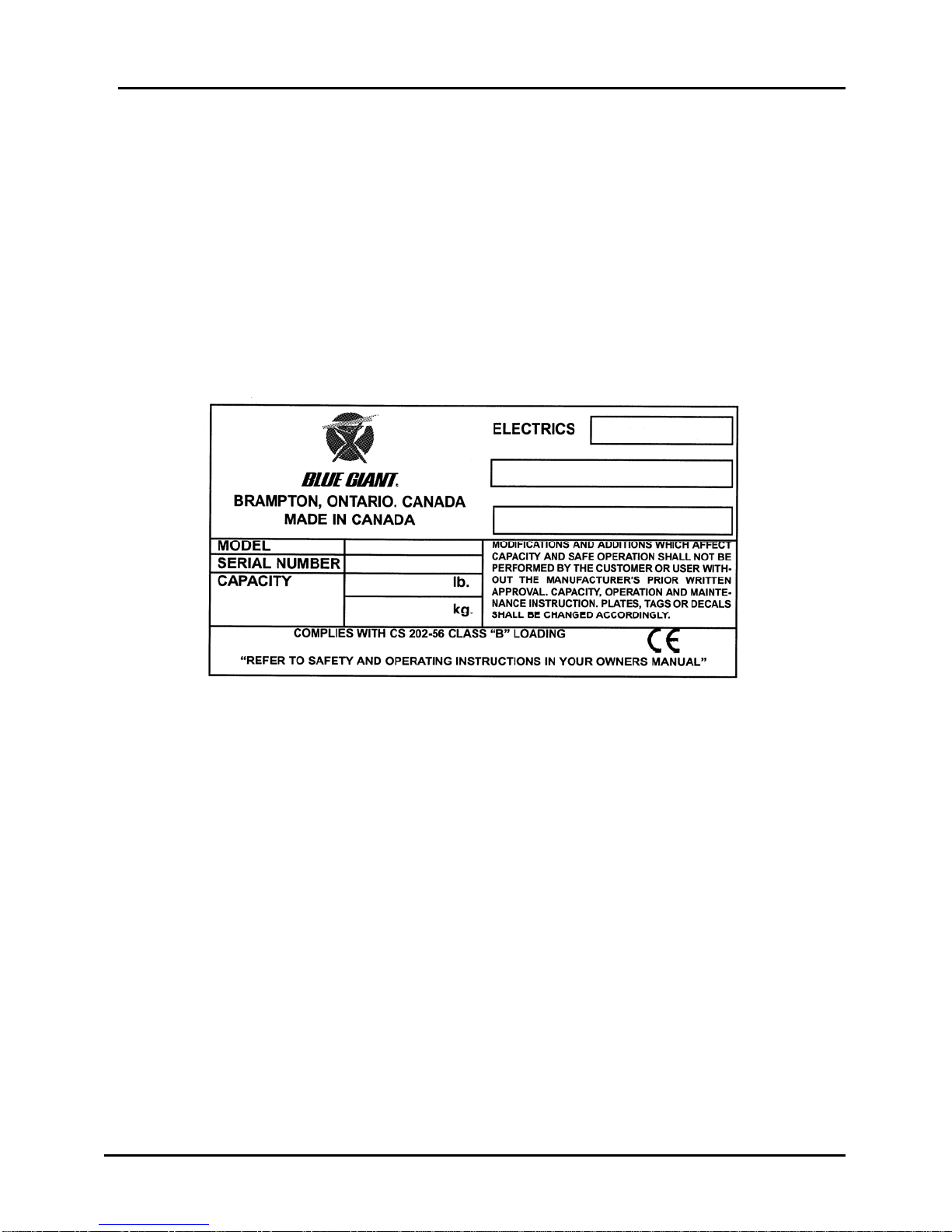
Blue Giant dock levelers are identified by information located on
an I.D. plate mounted on the upper, front, right hand side of the
unit.
Model number, Serial number and Capacity information is
included for use when requesting information or ordering service
parts.
The capacity listed must not be exceeded and includes total
weight of fork truck plus total weight of load being transported.
Group 02, Section 01, Page 2 Mechanical Dock Leveler – M and FMC
Issue Date: 10/01/01, Rev, 0 (Part #038-550E)
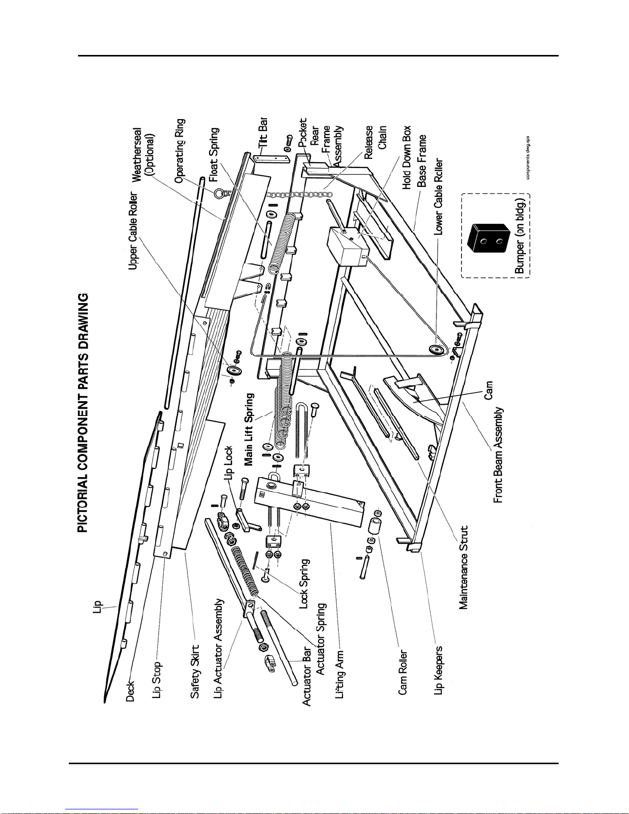
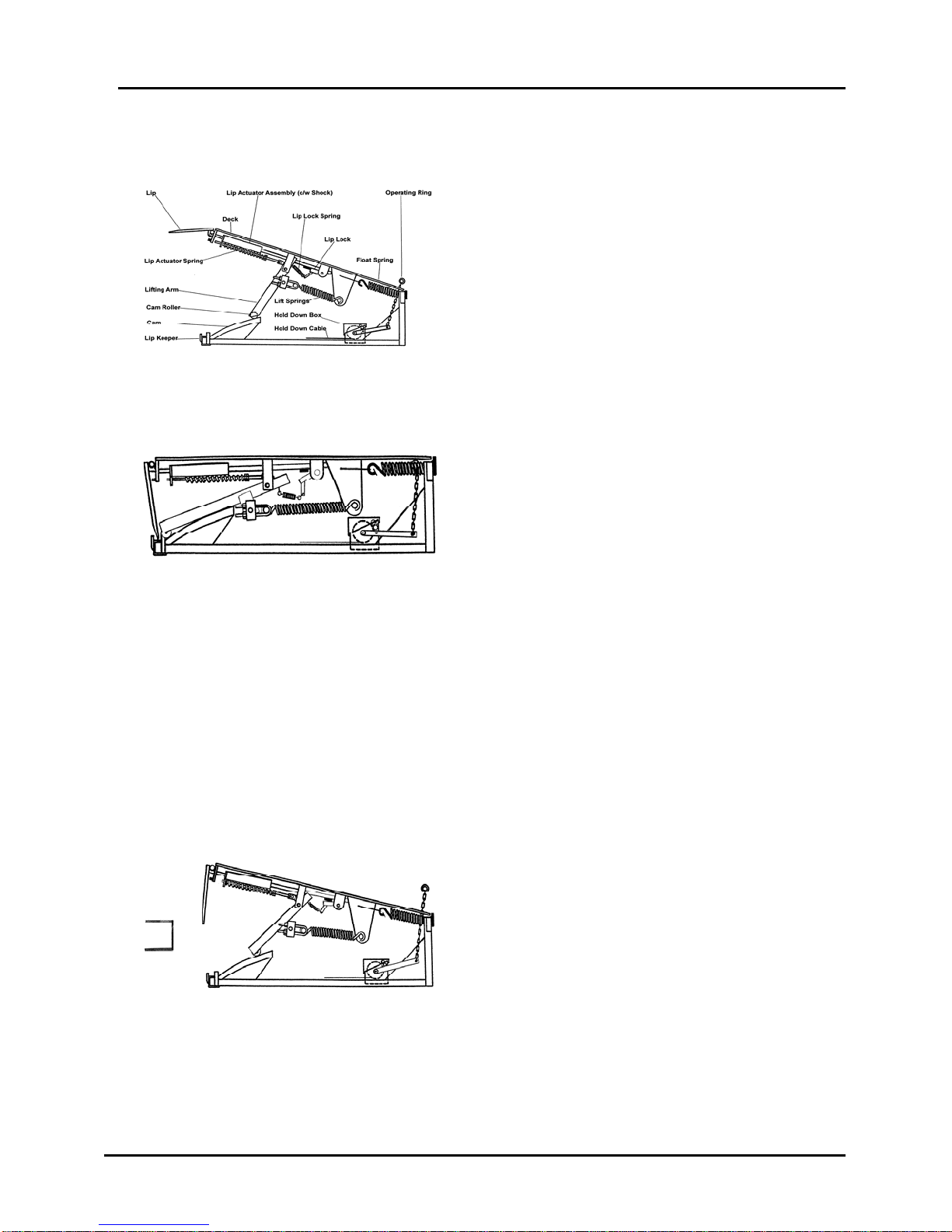
COMPONENT IDENTIFICATION

Mechanical Dock Leveler – M and FMC Group 02, Section 01, Page 3
Issue Date: 10/01/01, Rev. 0 (Part #038-550E)
INTRODUCTION and COMPONENT IDENTIFICATION
Right & Left Side The right side is identified by standing on the dock leveler
while facing the dock door and lip.
Base Frame
The angle iron mounting frame that is the base platform
for the entire dock leveler. It sits firmly on the bottom of
the dock pit and is the base that supports for the entire
leveler
Rear Frame Assembly
The rear portion of the Base Frame that contain the tilt
bar pockets.
Front Beam Assembly Front of Base Frame that contains the Lip Keepers and
provides mounting points for other components.
Cam The curved track that provides a ramp action. This ramp
action works in conjunction with the lifting arm, roller and
Main Lift Springs to elevate the deck.
Lifting Arm Roller
Attached to the lower end of the Lifting Arm, the Cam
Roller travels the contour of the Cam and allows smooth
low resistance movement while raising or lowering the
dock leveler deck.
Lifting Arm When pulled rearward by the Main Lifting Springs this
arm rotates around it's pivot point and by so doing,
transfers motion to the appropriate components of the
deck leveler.
Main Lift Springs Create the potential energy necessary to raise and
suspend the entire weight of the deck and lip.
Deck & Lip
The plates that become the bridge from the dock to the
truck floor
Tilt Bars & Pockets Floating hinge points located at the rear of the deck that
allow the deck to float diagonally and compensate for
irregularities in lateral truck positioning.
Lip This is the hinged plate on the outside edge of the deck.
It rests on the truck floor when the deck is in working
position.

Group 02, Section 01, Page 4 Mechanical Dock Leveler – M and FMC
Issue Date: 10/01/01, Rev, 0 (Part #038-550E)
INTRODUCTION and COMPONENT IDENTIFICATION
Lip Keepers These are the retainers for the Lip when it is in the park
position.
Lip Stops Prevent the Lip from traveling too far when parking the
dock leveler.
Lip Actuator Assembly
(Shock Assembly)
Works in conjunction with the forward motion of Lifting
Arm to extend and position the lip.
Actuator Spring
Provides cushioned thrust action when extending the Lip.
Actuator Bar
As part of the Lip Actuator Assembly it provides for
positively extending the lip.
Lip Lock Engages the Actuator Bar and locks it in the extended
position.
Lip Lock Spring
Transfers motion from the Lifting Arm to engage the Lip
Lock, with the Actuator Bar Lock Block.
Release Chain
Releases the Braking action of the Hold Down Box and
it's components.
Hold Down Box
(Load Roller & Wear Strip)
Provides a braking action through a cable to maintain
deck positioning by opposing the upward action of the
Main Lift Spring.
Float Spring
Located on the upper end of the Hold Down Cable it
allows for over-ride of brake action as the cargo or load is
removed from a truck.
Safety Skirt
The plates located on the sides of the deck commonly
referred to as "Toe Guards".
Maintenance Strut
As a maintenance device the adjustable strut is stowed in
the frame and is used to lock the dock leveler deck in the
up position while personnel are performing maintenance
or repairs on the underside of the dock leveler.
Building Bumpers
Molded rubber blocks mounted outside of the building
protruding from the outer sides of the dock leveler. They
protect the dock and leveler from shock from reversing
trucks (laminated type also available).

BLUE GIANT SERVICE MANUAL
Issue Date: 10/01/01, Rev. 0 Page 1
FORWARD
Each product section is identified by
description and Model Identification
and includes a pictorial listing of
components. A contents index is
placed at the beginning of each
section.
Procedures have been made easier
to use by providing specific steps only
when necessary and general
instructions required to explain the
activity, components, assembly, or
process being worked on. The
technician is expected to include
obvious additional steps of standard
procedures for removal, disassembly,
cleaning, inspection, reassembly,
installation, etc., as needed.
The technician is cautioned and
expected to take time to completely
read and understand the entire
procedure, including any special
instructions, to be better prepared to
do the necessary work before
beginning any work.
This Service Publication provides
information covering normal service,
maintenance and repair of Blue Giant
loading dock equipment listed on
Page 5. It has been specifically
prepared to help owners and service
personnel maintain this equipment in
safe and efficient operating condition.
This manual is intended for use by
persons who are trained and
authorized to perform loading dock
equipment maintenance. It is
designed to provide essential
information about the correct and
safe service, maintenance and repair
of the equipment by trained service
technicians.
General and detailed service and
repair procedures are outlined (as
required) for each product. Some
procedures include explanations that
are common to several components
or sub-systems.
NOTICE
The description and specifications included in this manual were in
effect at the time of printing. Blue Giant reserves the right to
discontinue models at any time, or make improvements and
changes in specifications or design without notice and without
incurring obligation. Specifications, pressures, measurements,
adjustments, illustrations, and other items may change at any time.
Contact your Blue Giant distributor for information on possible
updates or revisions.

SERVICE MANUAL BLUE GIANT
Page 2 Issue Date: 10/01/01, Rev, 0
SAFE MAINTENANCE PRACTICES
The following instructions have been
prepared from current industry and
government safety standards
applicable to dock equipment
operation and maintenance. These
recommended procedures specify
conditions, methods, and accepted
practices that aid in the safe
maintenance of dock equipment.
They are listed here for the reference
and safely of all workers during
maintenance and repair operations.
Carefully read and understand these
instructions and the specific
maintenance procedure before
attempting to do any repair work.
When in doubt of any procedure,
contact your Blue Giant distributor
for assistance.
•Dock equipment can become
hazardous if maintenance is
neglected. Therefore, trained
personnel and procedures must
be provided.
•Maintenance and inspection of all
dock equipment shall be done in
conformance with the
manufacturers recommendations.
•A scheduled planned
maintenance, lubrication and
inspection program shall be
followed.
•Avoid fire hazards and have fire
protection equipment present in
the work area.
•Only trained and authorized
personnel shall be permitted to
maintain, repair, adjust and
inspect dock equipment. Work
should be performed in
accordance with the
manufacturers specifications.
•Do not use open pans of fuel or
flammable cleaning fluids for
cleaning parts.
•Before starting work, wear eye
protection and remove all jewelry.
•Always engage maintenance strut
and place traffic barriers before
entering pit area.
•There are numerous variations in
procedures, techniques, tools and
parts for servicing dock
equipment, as well as in the skill
of the individual doing the work.
This manual can not possibly
anticipate all such variations and
provide advice or precautions as
to each. Accordingly, anyone
departing from the instructions
provided in this manual through
procedures used or choice of
tools, materials and parts, may
jeopardize his or her personal
safety and / or the safety of the
equipment operator.
•Improper or careless techniques
cause accidents. Read and
understand the procedures for
safe maintenance outlined in this
manual.
•Work safely and follow the safety
signs and their messages
displayed in the work area and in
this manual.
BLUE GIANT SERVICE MANUAL
Issue Date: 10/01/01, Rev. 0 Page 3
SAFETY SIGNS and SAFETY MESSAGES
Improper operation can cause accidents. Don’t take chances with incorrect or damaged
equipment. Read and understand the procedures for safe operation and maintenance
outlined in this manual. Don’t hesitate to ask for help.
Stay alert! Follow safety rules, regulations, and procedures. Avoid accidents by
recognizing dangerous procedures or situations before they occur.
Safety signs and messages are placed in this manual to provide instructions and
identify specific areas where potential hazards exist and special precautions should be
taken. Know and understand the meaning of these instructions, signs, and messages.
Damage to the dock equipment, death, or serious injury to you or other persons may
result if these messages are not followed. If warning decals are damaged, they must be
replaced. Contact your Blue Giant Distributor for replacements.
NOTICE
This message is used when special information, instructions or
identification are required relating to procedures, equipment, tools,
capacities and other special data.
IMPORTANT
This message is used when special precautions should be taken to
ensure a correct action or to avoid damage to or malfunction of the
dock equipment or a component.
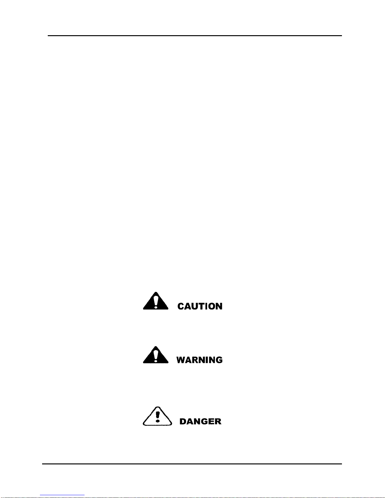
This message indicates a potentially hazardous situation which,
if not avoided, may result in minor or moderate injury
This message indicates a potentially hazardous situation which, if
not avoided, could result in death or serious injury.
This message indicates an imminently hazardous situation which,
if not avoided, will result in death or serious injury.

SERVICE MANUAL BLUE GIANT
Page 4 Issue Date: 10/01/01, Rev, 0
PLANNED MAINTENANCE
The importance of proper
maintenance through planned
service, inspection, and qualified
repairs can not be emphasized too
strongly. Planned maintenance
instructions are provided for
reference in setting up and
conducting a recommended periodic
Planned Maintenance (PM) program.
Planned maintenance is a program in
which inspections, cleaning, minor
adjustments, are performed on a
scheduled and systematic basis. A
solid PM program should incorporate
a method of record keeping which
enables you to better determine PM
schedules and enables you to track
the maintenance costs.
An effective PM program should
incorporate two basic phases:
•An inspection performed by
operator or maintenance man at
the beginning of each shift. This
is a quick visual check for obvious
damage.
•A planned maintenance routine
performed every three months
based on a single shift operation
or monthly for multi-shift
operations.
Minimum work to be performed at
each planned maintenance interval:
•Cleaning, including surrounding
area.
•Visual inspection of all
components.
•Test operate all functions.
•Lubricate as required.
•Adjustment and retest if required.
•Check for damaged dock
bumpers.
•Record inspection details and
findings for owners files.
If the PM is routinely followed, need
for repair, major adjustment, and
component replacement will be
discovered automatically and such
work can be scheduled, eliminating
unnecessary down-time and cost.
The objectives of PM are:
•To reduce costly unscheduled
down-time.
•Reduce maintenance costs.
•Increase loading dock
productivity.
•Increase personal safety of
operators and other personnel.
Refer to the Operators Manual,
located with the dock equipment, for
additional information on care and
maintenance of your equipment.
NOTICE
Contact your Blue Giant Distributor for more information on
Maintenance and Re
p
air of
y
our Dock E
q
ui
p
ment.

BLUE GIANT SERVICE MANUAL
Issue Date: 10/01/01, Rev. 0 Page 5
PRODUCTS COVERED BY THIS MANUAL
PRODUCT MODEL CODE
M 721
Dock Leveler – Mechanical – Pit Mounted FMC 722
FH 731
Dock Leveler – Hydraulic – Pit Mounted FHE 732
FHC 733
Dock Leveler – Hydraulic – Vertical Storing VS 751
E.O.D. Dock Leveler – Mechanical – Edge of Dock MD-M 704
E.O.D. Dock Leveler – Hydraulic – Edge of Dock MD-H 704
Truck Restraint – Mechanical ML-10 730
Truck Restraint – Hydraulic – Self-Contained Power Pack TL-85 735
Truck Restraint – Hydraulic – Remote Power Pack TL-85A 735
Truck Restraint and Dock Leveler - Combination TL-85A 740
ED 815
Elevating Dock – Hydraulic – Pit / Surface Mounted Lomaster 812
Elevating Dock – Hydraulic – Semi-Portable 4S/ 5S x 6S 810
Lift Table – Hydraulic – Pit / Surface Mounted FS 830
Lift Table – Hydraulic – Double Scissor DS 840
HOW TO USE THIS MANUAL
Separated and Identified by ‘Tab Pages’.
Products:
Each product is divided into ‘Groups’ of common information.
Group:
Each group is separated into main component ‘Sections’.
Section:
Each section page is numbered individually.
Page:

Mechanical Dock Leveler – M and FMC Group 03, Section 01, Page 1
Issue Date: 10/01/01, Rev. 0 (Part #038-550E)
Theory of Operation
Mechanical Dock Leveler
Index
SUBJECT GROUP SECTION PAGE
Description of Operation 03 01 2
Walking the Dock into Working Position 03 01 2 –3
Return to Stored Position 03 01 3
Diagonal Float Ability 03 01 3
Fall Safe Feature 03 01 4
Detail of Component Functions 03 01 5 - 7
Hold Down in Locked Position 03 01 8
Hold Down in Unlocked Position 03 01 8
Below Level Feature 03 01 9
Maintenance Strut 03 01 10

Group 03, Section 01, Page 2 Mechanical Dock Leveler – M and FMC
Issue Date: 10/01/01, Rev, 0 (Part #038-550E)
DESCRIPTION OF OPERATION
Before moving the dock leveler from
the stored position, it is most important
to chock the vehicle wheels or
otherwise secure the vehicle to prevent
its movement away from the dock,
before operating the Dock Leveler.
In stored position the lift springs are
stretched and the lifting arm is at the
base of the cam. The loaded springs
are fully tensioned in this position and
are always trying to pull the Lifting Arm
to the rear. The dock leveler can not
move upward however since it is held
in position at floor level by a “hold
down" mechanism. As you can see
above the "Lip" is folded down and is
being retained by the "Lip Keepers".
To raise the Dock Leveler deck, one must firmly pull up the release ring in the left-rear
corner of the deck and hold it up until the deck lift springs fully raise the deck. The lip will
automatically extend and will lock as the deck reaches its fully raised height.
WALKING THE DOCK INTO
POSITION
The deck is lowered by the operators
weight as he walks up it’s slope. The
extended lip makes firm contact with
the truck bed. At this point the bridge
is formed and the entire weight of the
outer end of the dock deck is supported
by the lip resting on the truck bed
Note: It is important to note that even though the lift springs are always trying to lift
the dock deck, their upward force is being opposed by the action of the “Hold Down
Mechanism". The unit is now considered to be ready for lift truck traffic.

Mechanical Dock Leveler – M and FMC Group 03, Section 01, Page 3
Issue Date: 10/01/01, Rev. 0 (Part #038-550E)
RETURN TO STORED POSITION
To return the deck to stored position after
the vehicle is Loaded or Unloaded and is
still at the dock, pull up and hold the
release chain "only long enough" for the
lip to clear the truck bed and fold in fully.
WALK THE DECK DOWN
Walk the deck down to the stored
position, ensuring that the lip is located
inside the lip keepers.
Note: Releasing the operating ring at any time will stop the upward travel of the deck.
Note: Should the truck depart before the dock leveler is returned to stored position, the
lip will automatically swing down to a hanging position. If the truck being serviced was
lower than the dock and the lip is not located inside the keepers, raise the deck
approximately 12” above dock height and then walk it down to stored position.
DIAGONAL FLOAT ABILITY
Irregularities in left to right corner height of the truck floor are sometimes caused by
uneven paving or lop sided loads. The design of the Blue Giant Dock Leveler
incorporates the use of "Tilt Bars and Pockets". These are floating hinge and mount
points located at the rear of the deck that allow the deck to float diagonally and
compensate for irregularities in left to right corner height of the truck floor. This
extends deck life by preventing deck twisting and also prevents lift truck tire damage
by allowing full width lip contact.
Note: In use, the Dock Leveler deck adjusts itself to tilted load beds and raises and
lowers automatically with movements of the load bed. (It is normal for a rear corner
to raise above floor level during use to compensate for a tilted truck bed).

Group 03, Section 01, Page 4 Mechanical Dock Leveler – M and FMC
Issue Date: 10/01/01, Rev, 0 (Part #038-550E)
FALL SAFE FEATURES
A fall safe device is included on all U.S. dock levelers and is available
as an option in all other countries.
Its purpose is to limit the free fall of the deck to 1-1/2” below dock
height if a trailer pulls away when a fork truck is on the dock leveler.
Two solid steel support legs are maintained in position between the
underside of the deck and the pit floor to limit the downward travel of
the deck.
The support legs are welded to a common shaft and maintained in
working position by a spring.
Pulling a control ring and chain at the front left corner will retract the
support legs to allow below level operation. Deck must be raised
approximately 4” to retract legs.
Mechanical Dock Leveler – M and FMC Group 03, Section 01, Page 5
Issue Date: 10/01/01, Rev. 0 (Part #038-550E)
DETAIL OF COMPONENT FUNCTIONS
In the previous descriptions outlined in
this section we explained the general
operation of the Mechanical Dock
Leveler. In this part of the operation
section we will explain the detail of the
various key components such as the
Lifting Arm, Lip Actuator Assembly,
Hold Down box and Cable, etc.
Notice that as the arm travels rearward on
the cam, two motions occur. The cam
roller and arm move rearward. The upper
part of the arm moves forward above the
pivot point. Because the roller is moving
rearward – it is traveling up the cam –
raising the deck. Because the top of the
Lift Arm is moving forward – its motion is
transferred through the Lip Actuator Spring
to extend the lip. This “point of contact”
(spring to lip) is what decides at what
“deck raising point” the lip is extended and
also modulates or cushions the action
extending the lip. This is a critical
adjustment that rarely changes and is
made at the factory.
Did you notice that in the previous statement we were careful to say that the Lift Springs
were “being allowed” to pull the Lift Arm rearward. When the Operating Ring and chain
are in their normal position, the hold down box and cable are always creating a
resistance or braking action that does not “allow” the weight of the deck to be lifted by
the biased Lift spring, Lift Arm and Cam action. When there is no weight on the deck, it
is always capable of being lifted by the springs.
All functions work in combination with,
and as a result of the lifting arm motion
as it is rotated around its axis by the
Lift Springs. As you can see here, the
cam and by the action of the Lift
Springs “being allowed” to pull the Lift
Arm rearward, the deck is raised. It is
important to observe the rotation action
of the arm around it’s pivot point.
Group 03, Section 01, Page 6 Mechanical Dock Leveler – M and FMC
Issue Date: 10/01/01, Rev, 0 (Part #038-550E)
DETAIL OF COMPONENT FUNCTIONS – cont’d
In this view the deck has been allowed to
raise to the point where the actuator
extended the lip. Notice that as the
actuator assembly moved forward – the lip
lock was pulled into its locking position.
The spring will maintain tension on the lip
lock while the deck is in the raised
position. When the deck is walked down
by the weight of the operator – the weight
of the lip will be supported by the lip lock.
After the loading / unloading process is complete – the operator pulls the release
chain to release the hold down device. The operator can now allow the dock deck to
raise high enough to allow the lip (now unlocked) to drop into its hanging position.
The lip is now ready and in position to enter the lip keepers when the operator walks
it down.
The lip and the lip keepers will now support the outer weight of the deck assembly in
the stored position. We have previously referred to the
opposing force or braking action of the
hold down box and cable, on the biased lift
springs. In this picture we can follow the
cable routing. The cable is attached
through a float spring to the rear solid
portion of the dock leveler deck. It is
routed forward to a pulley that is mounted
at the front of the deck. It then proceeds
downward through another pulley that is
mounted on the lower front beam of the
stationary frame. The cable then extends
rearward where it enters the hold down
box where tension is applied by a rewind
spring.
This view shows the deck lowered and the
weight of the deck now being supported by
the truck floor.
At this time the actuator and the lip lock
have done their job. Because the weight of
the lip has been taken by the truck floor –
the weight of the lip is no longer exerting
force on the lip lock. The fact that the Lift
Arm is now in a lower position – the spring
is relaxed – gravity takes over and allows
the lip lock to drop out of locked position.
Mechanical Dock Leveler – M and FMC Group 03, Section 01, Page 7
Issue Date: 10/01/01, Rev. 0 (Part #038-550E)
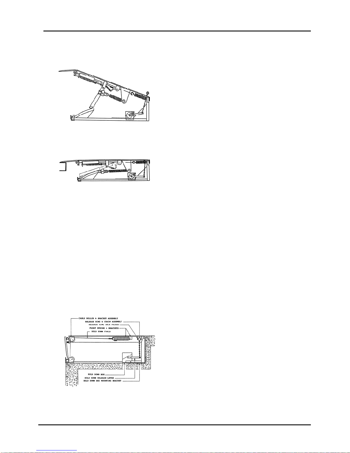
DETAIL OF COMPONENT FUNCTIONS – cont’d
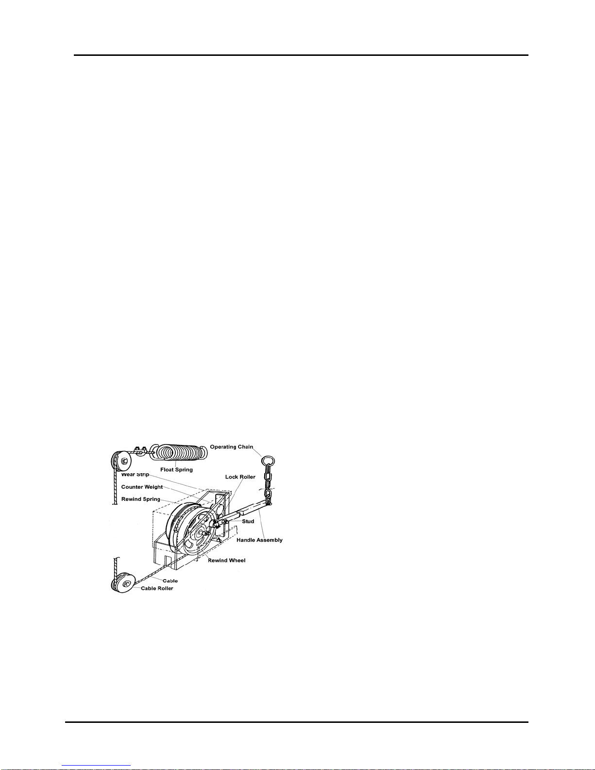
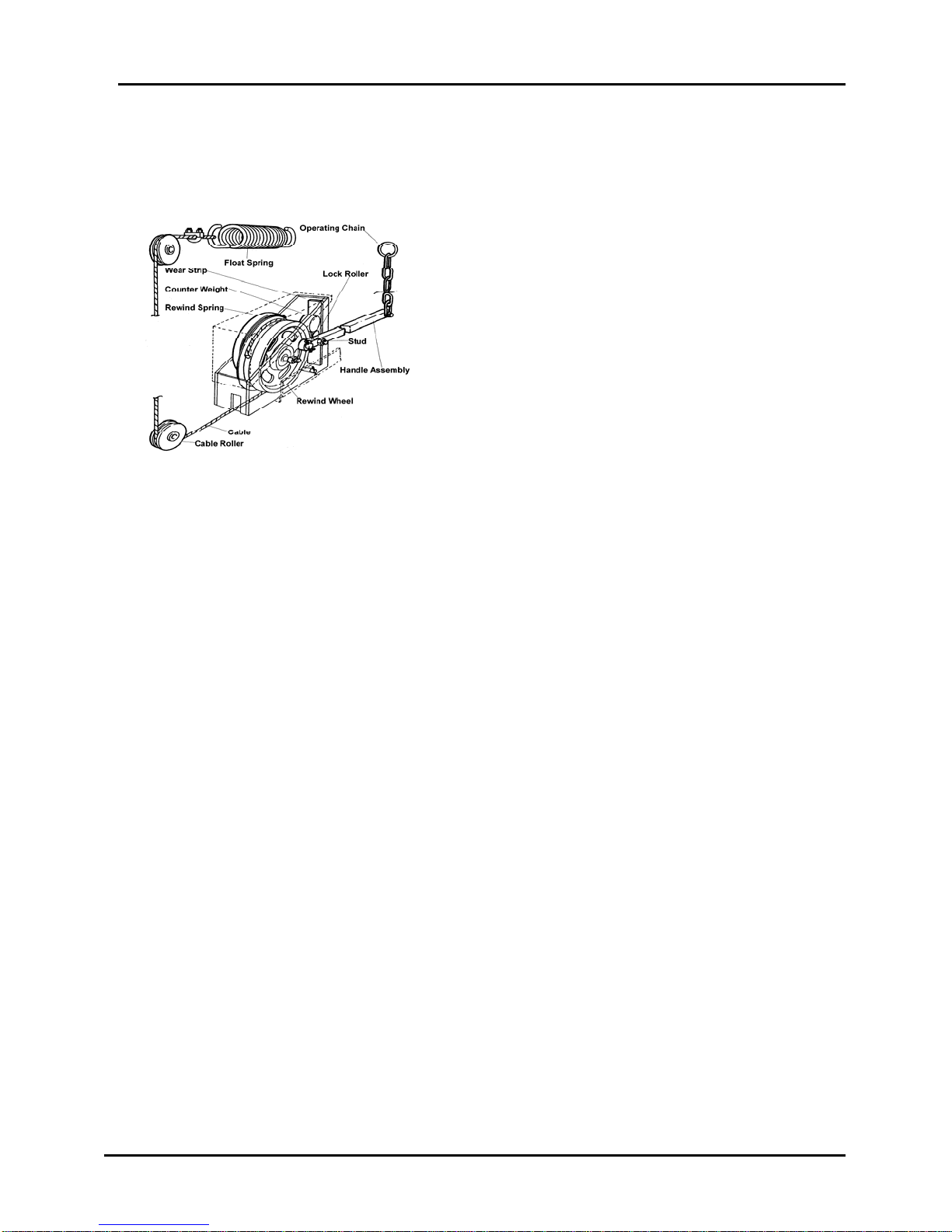
In this picture you can see the
working components of the hold
down system.
They are:
–Handle Assembly
– Rewind Wheel
– Coil Spring
– Wear Strip
– Counter Weight
– Knurled Lock Roller
– Cable, etc.
The hold down mechanism is
designed to work as a one-way
direction check for the cable.
As you can see here, the rewind spring is always trying to pull the cable
towards the hold down box. The rewind spring only has enough power
to rewind the cable as the deck moves downward.
The cable can always move toward the box when the deck is moving
downward however, because of the braking action applied to the cable
by the hold down box, the cable can not move outward until the brake is
released by pulling the operating chain.
This devices makes sure that the dock leveler always maintains a
positive downward force – through the lip when it is engaged with the
truck floor.
Since the brake creates a positive downward action to keep the lip
engaged with the truck floor, it is necessary to provide for and allow
movement of the deck and lip in an upward direction. This would occur
as a truck is being unloaded. As the load on the truck lightens, the
suspension tends to raise the truck bed.
As you can see here – this non-positive cushioned action is provided
through the cable by the float spring.
Group 03, Section 01, Page 8 Mechanical Dock Leveler – M and FMC
Issue Date: 10/01/01, Rev, 0 (Part #038-550E)
HOLD DOWN IN LOCKED POSITION:
The “one-way direction check” is created by
the action of the lower “Lock Roller” which is
held downward by the upper “Counter
Weight” roller.
In this position the “Lock Roller” is wedged
between the “Wear Strip” and the flat
surface of the “Rewind Wheel”. This
wedging action is sufficient to prevent the
“Rewind Wheel” from turning clockwise.
This prevents the cable from pulling outward
due to opposing lift spring force (which is
always present) attempting to lift the deck.
External force trying to lift the dock leveler
deck as explained earlier, (truck-load
lightening and forcing the lip and deck
upward) will not pull the cable through the
brake. Instead the “Float Spring” allows for
this necessary flexibility while maintaining a
positive contact from lip to truck.
HOLD DOWN IN UNLOCKED POSITON:
The “Handle Assembly” shown here pivots around the shaft on which it is mounted.
A short distance from this shaft is a horizontal “Stud” that is positioned underneath the
“Lock Roller”.
When the operator wishes to raise the deck he / she must pull up on the “Handle
Assembly” by pulling the “Operating Chain” upward. The horizontal “Stud” then lifts the
“Lock Roller” from its wedged position between the flat surface of the “Rewind Wheel”
and the “Wear Strip”.
This releases the cable and allows the deck to move upward as required. After the
deck reaches the desired level and the “Lip” is extended – the operator releases the
“Operating Chain” – walks up the raised deck and with his / her own weight forces the
deck and extended lip down to contact the truck floor.
During the “walk down” process the “Rewind Spring” is pulling and winding the
slackening cable back on the wheel until deck travel stops. The only way the deck can
move upward now is by overcoming the tension of the “Float Spring”.
The “Float Spring” allows the deck to raise with the truck bed. If there was no “Float
Spring” the cable or some other component would break.

Mechanical Dock Leveler – M and FMC Group 03, Section 01, Page 9
Issue Date: 10/01/01, Rev. 0 (Part #038-550E)
BELOW LEVEL FEATURE
Fall Safe support legs prevent
service of below dock height truck
bed and / or end load.
Raise dock leveler approximately
4”. Pull and hold control ring and
chain.
Pull and hold control ring and chain
located in front left corner of deck.
Legs retract and lip moves out
beyond lip keepers.
Hold tension on control chain and
walk the deck down. Support legs
will retract further, as required.
Deck will lower to below level stops
(not shown for clarity of other
components). End or below level
loads may be serviced.
A vehicle loadbed that is lower than dock height may be serviced by using
the below level feature.
This manual suits for next models
1
Table of contents
Other Blue Giant Tools manuals


