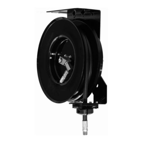
Balcrank Signature Series Instruction Manual

®
Models: 2120-XXX
See page 3 for Hose Reel Model
Numbers and Technical Data
SIGNATURE™REELS
Multi-Purpose Transfer
OPERATION, INSTALLATION,
MAINTENANCE AND REPAIR GUIDE
Thoroughly read and understand this manual before
installing, operating or servicing this equipment.
SERVICE BULLETIN SB2002
REV. R 01/14

Read these safety warnings
and instructions in this manual
completely, before installation and start-up of the
reel. It is the responsibility of the purchaser to retain
this manual for reference. Failure to comply with
the recommendations stated in this manual will
damage the reel and void factory warranty.
IMPORTANT
!
General Safety
Thoroughly read and understand this manual
before installing, operating or servicing this
equipment.
Because this Hose Reel can be
incorporated into a pressurized
systems, the following safety precautions should be
observed.
Check equipment regularly and repair or replace
worn and damaged parts.
Never alter or modify any parts of this hose reel,
doing so may cause damage to hose reel and/or
personal injury.
Under no circumstances should the dispensing
valve be aimed at any person at any time. Personal
injury may result.
Release pressures built up in the system before any
service or repair is begun. See the pressure relief
procedure below.
Do not operate bare air/water or lube reels above
3000 psi (206.9 bar). Do not operate bare grease
reel above 5000 psi (620.6 bar).
NOTE: If reel is equipped with hose, reel maximum
pressure will be determined by the lowest working
pressure rating of the hose, bare reel, or dispense
valve.
Always read and follow the uid manufacturer’s
recommendations regarding the use of protective
eyewear, clothing and respirators.
IMPORTANT
!
Pressure Relief Procedure:
Follow this procedure before maintaining and/
or repairing your Premium Hose Reel and/or
any part of system.
1) Disconnect the air to the pump.
2) Point dispensing valve away from
yourself and others.
3) Open dispensing valve until
pressure is relieved.
WARNING
!
The spring is ALWAYS under great tension and
could be propelled from the case with enough
force to cause serious bodily injury.
CAUTION
USE EXTREME CARE WHEN
HANDLING THE POWER SPRING!
!
Be sure the mounting
surface is strong enough to
support the reels, the
weight of the uids and the
stress caused by hard pulls on the service
hoses. See page 3 for dry weights of the hose
reel assemblies.
WARNING
!
WARNING
!
The MAXIMUM WORKING
PRESSURE of a hose reel is determined by the
lowest rated component in the assembly. The
hose reel Technical Data chart on page 3 give
the maximum working pressure of bare reels
and reels assembled at the factory with hose.
The maximum working pressure of a hose reel
is indicated on the hose reel identication plate
located near the base of the reel.
If adding a service hose and dispensing valve to
a bare reel, BE SURE you know the maximum
working pressure of ALL components!
WARNING
!
DANGER: Not for use with uids that
have a ash point below100°F (38°C).
Examples: gasoline, alcohol. Sparking
could result in an explosion which could
result in death.
CAUTION
!
Fully extend hose before pressurizing or damage
may occur to side panels
CAUTION
!
Be aware of possible uid thermal expansion! A
pressure relief valve should be properly installed in
any system where this product is used. Should this
product fail as a result of thermal expansion and
no pressure relief valve was installed, the product
warranty will be voided.
2

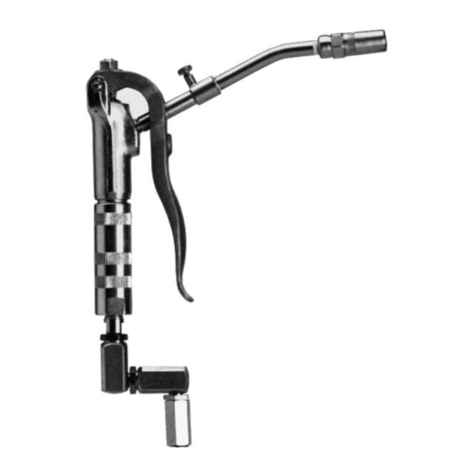
TABLE OF CONTENTS
Cover...................................................................... 1
General Safety Information..................................... 2
Technical Data........................................................ 3
Model Numbers ...................................................... 3
Mounting Dimensional Data ................................... 4
TECHNICAL DATA
Maximum Fluid Working Pressure:
Low Pressure Reels (bare)........................ 3000 psi
Medium Pressure Reels (bare).................. 3000 psi
High Pressure Reels (bare)....................... 5000 psi
Wetted Parts:
Low & Med. Pressure .......... Steel (plated), Buna-N
Bronze, Brass
High Pressure...................... Steel (plated), Buna-N
........................................................Hardened Steel
Installation ........................................................4 & 5
Maintenance........................................................ 6-9
Parts Listing...........................................................11
Warranty ............................................................... 12
Hose Working Pressure Ratings:
Air/Water Hose .................................. 3/8” – 300 psi
1/2” – 300 psi
Nitrogen Hose.................................... 3/8” – 300 psi
Med. Pressure ................................. 1/2” – 3000 psi
High Pressure.................................. 1/4” – 5000 psi
3/8” – 4000 psi
Shipping Weight Bare Reels:
Std. Frame (35 ft hose or less)..................... 45 lbs.
Lrg. Frame (40 ft & above) ........................... 49 lbs.
*Reference installation instructions on page 4 item #7, fully extend hose before pressurizing.
3
MODEL NUMBERS
Type of
Service Model No. Hose Size Max Working
Pressure Outlet Hose Inlet Hose Bare Reel
Low Pressure Air,
Water
Inlet
1/2” NPT(M)
Outlet
3/8” Hose - 1/4” NPT(M)
1/2” Hose - 1/2” NPT(M)
2120-014 30’ x 3/8” 300 psi 8136-030 8142-002X 2120-016
2120-005 40’ x 3/8” 300 psi 8136-040 8142-002X 2120-017
2120-015 50’ x 3/8” 300 psi 8136-050 8142-002X 2120-017
2120-020 50’ x 1/2” 300 psi 8141-050 8142-002X 2120-017
Med. Pressure
Oil, ATF, Antifreeze
Inlet - 1/2” NPT(M)
Outlet - 1/2” NPT(M)
2120-011 30’ x 1/2” 3000 psi 8241-030 8249-002X 2120-016
2120-012 40’ x 1/2” 3000 psi 8241-040 8249-002X 2120-017
2120-013 50’ x 1/2” 3000 psi 8241-050 8249-002X 2120-017
High Pressure
Grease
Inlet - 3/8” NPT(M)
Outlet - 1/4” NPT(M)
2120-001* 30’ x 1/4” 5000 psi 8321-030 8334-002X 2120-018
2120-002* 40’ x 1/4” 5000 psi 8321-040 8334-002X 2120-019
2120-006* 50’ x 1/4” 5000 psi 8321-050 8334-002X 2120-019
2120-003* 30’ x 3/8” 4000 psi 8331-030 8334-002X 2120-018
2120-004* 40’ x 3/8” 4000 psi 8331-040 8334-002X 2120-019
2120-007* 50’ x 3/8” 4000 psi 8331-050 8334-002X 2120-019
Nitrogen
Inlet - 1/2” NPT(M)
Outlet - 1/4” NPT(M)
2120-025 30’ x 3/8” 300 psi 8135-030 8142-002X 2120-016
2120-026 50’ x 3/8” 300 psi 8135-050 8142-002X 2120-017
Bare Reels
Bare Reel
Model
Max. Hose
Capacity
Bare Reel
Max W.P. (psi)
Thread Size
Inlet Outlet
NPT(F) NPT(F)
Reel Dimensions
L. W. H.
2120-016 40’ x 1/2” 3000 psi 1/2” 1/2” 16” 6” 17.5”
2120-017 50’ x 1/2” 3000 psi 1/2” 1/2” 16” 8” 17.5”
2120-018 40’ x 3/8” 5000 psi 3/8” 1/4” 16” 6” 17.5”
2120-019 50’ x 3/8” 5000 psi 3/8” 1/4” 16” 8” 17.5”

PRODUCT DESCRIPTION
The Signature™Series hose reel is designed to
provide efcient delivery of air, water, oil, or grease
through various hose lengths, at an economical
price. The inlet (shaft) and outlet (swivel) are
threaded. The roller outlet arm can be adjusted to
any one of ve positions, which allows oor, table,
wall or ceiling mounting (when mounting directly to
I-beam, clamping kit no. 2230-017 is available for
ease of assembly.)
NOTE: Model 2120-015 with 50ft. air/water hose is
shown. 30 ft. reels are 6” wide, all others are 8” wide.
Additional bolt holes are provided in the base to t
the 3” x 4” bolting pattern used on previous versions
a Signature™Series hose reels.
DIMENSIONS &
MOUNTING DIAGRAM
(Mounting Footprint located on page 10)
Do not hard pipe inlet/swivel to any existing
structure/system. Flexible connection hose must
be used to maintain swivel performance.
!
NOTE
Be sure the mounting surface
is strong enough to support the reels, the
weight of the uids and the stress caused by
hard pulls on the service hoses. See page 3
for dry weights of the hose reel assemblies.
WARNING
!
6” or 8”
1-5/8”
3/8” npt
High Pressure
1/2” npt
Low/Med
Pressure
Inlet
16” Rim dia
Figure 1
11”
Holes for (4)
3/8” bolts
17-1/2”
9-3/4”
16”
Figure 2
4
INSTALLATION
Tank/Wall Mounting:
The hose reel is shipped ready to use; the power
spring tension has been adjusted for table/wall
mounting unless ordered without hose. If a bare reel
has been ordered see installation of hose instructions
and power spring adjustment on following steps.
1. Select the mounting location. Be sure the
mounting structure is secure and will not tip
when reel is in operation. Tables should be
bolted to oor and wall should be part of building
structure.
2. Locate the mounting holes for drilling, using
measurements on previous page.
3. Adjust the outlet arm position as required by
loosening and removing the four 10-32 locknuts
(43). Once arm is positioned correctly retighten
to 80 to 90 inch pounds.
4. Fasten the base using bolts of a sufficient
strength to prevent the reel from “shearing bolts”
during operation when hose is pulled.
5. Connect supply line to the inlet of hose reel.
6. If you are installing a hose onto a Bare Reel,
connect the service hose to the swivel union (2).
Then wrap the hose loosely around the spool.
Extend the hose fully and engage the stop pawl.
Wrap one to two loops around the spool, then
retract the hose again.
NOTE: Check the power spring tension; the
hose must pull out fully and retract fully. Wrap
ONE more loop onto spool, extend the hose, and
latch it. Do this as many times as necessary until
the power spring has the desired tension.
7. Install the hose stop and dispensing valve.
Position the hose stop so the hose extends far
enough for all operators to reach it. CAUTION:
Always Fully Extend hose before pressurizing or
damage may occur to side panels.

Ceiling Mounting:
The power spring tension will need to be adjusted
for the ceiling height of the building. If a bare
reel has been ordered see installation of hose
instructions and power spring adjustment on the
following steps.
1. Select the mounting location. If the ceiling is
very high, suspend a suitable support structure
for the reels, so the hoses will be long enough
to reach service area.
2. Locate the mounting holes for drilling, using
measurements on previous page. If mounting
directly to H-Beam use mounting kit 2230-017
(no drilling required).
3. Adjust the outlet arm position as required by
loosening and removing the four 10-32 locknuts
(43). Once arm is positioned correctly retighten
to 80 to 90 inch pounds.
4. Fasten the base using bolts of a sufficient
strength to prevent the reel from “shearing bolts”
during operation when hose is pulled.
5. Connect supply line to the inlet of hose reel.
6. Hose reels shipped with hoses come from the
factory with the tension preset for a typical
table/wall installation. For a ceiling installation
you will need to adjust for more or less tension,
by removing or adding one to two wraps of
hose from spool.
7. If your are installing a hose onto a Bare Reel,
connect the service hose to the swivel union
(2). Then wrap the hose loosely around the
spool. Extend the hose fully and engage the
stop pawl.
8. Wrap one to two loops around the spool, then
retract the hose again.
NOTE: Check the power spring tension; the hose
must pull out fully and retract fully. Wrap ONE more
loop onto spool, extend the hose, and latch it Do this
as many times as necessary until the power spring
has the desired tension.
9. Install the hose stop and dispensing valve.
Position the hose stop so the hose extends far
enough for all operators to reach it.
CAUTION: Always Fully Extend hose before
pressurizing or damage may occur to side
panels.
TYPICAL INSTALLATIONS
2230-017
MOUNTING
BRACKET KIT
(FOR I-BEAM MOUNTING)
Ceiling Mounting
Typical Inlet Line
Conguration
ELBOW DROP
TO REEL
SUPPLY
LINE
SHUTOFF
VALVE
2 ft. CONNECTING HOSE
TO REEL INLET
Model 2230-014
Hose Reel Mounting Plate
1. Bolt the hose reel mounting plate onto the
mounting channel.
2. Install rear bolts loosely on the mounting plate.
3. Slide the slotted side of the hose reel base
into position and hold with the integrated swing
clamp which is part of the adapter plate.
4. This leaves both hands free to install and tighten
the nuts and bolts which secure the hose reel in
nal installed position.
Figure 3
Figure 4
Figure 5
CAUTION: Do Not put so many loops onto
the reel that the power spring winds tightly before the
hose is fully extended. A power spring that has been
wound too tight stops rotating before the hose is fully
extended. This condition will wear the hose and power
spring prematurely. To decrease tension, remove one
to two loops of hose from the reel.
!
5

MAINTENANCE
Replacing Service Hose:
1. Be sure the pressure supply has been
relieved. Follow the pressure relieve
procedures below.
2. Pull hose on reel down just enough to allow
stop pawl to engage ratchet. This will lock
reel into position.
3. Remove the dispensing valve and hose
stop.
Swivel Seal Assembly
Backups
(2 EA.) Backups
(2 EA.)
O-RINGS
Replacing Seals in Swivel:
1. Be sure the system pressure has been
relieved. Follow the pressure relieve
procedures below.
2. Disconnect inlet hose. Remove the reel to
work bench and clamp reel base securely.
3. Extend the hose fully and latch the reel.
Unscrew service hose from swivel union
(2). Remove the retaining ring (6) and swivel
elbow (2).
4. Remove the worn o-rings (4) and backups
(3). Clean the swivel shaft and inspect for
wear or damage. Grease the new o-rings
and swivel shaft. Install the new o-rings
and backups, refer to gure 6 below for
pictorial illustration for assembling o-rings
and backups.
Figure 6
4. Wearing Heavy Leather Gloves, firmly
grab the outside edge of the spool with both
hands. Let the spool rotate slowly through
your hands until the spool stops. When
the spool stops the spring tension will be
released. The hose can now be unwrapped
and removed from the reel.
5 From open side of reel begin to wrap new
hose around spool in a clockwise direction.
6. Pull hose out through roller outlet and
reassemble hose bumper stop and
dispensing Control Handle.
7. Position the bumper stop so that the hose
will extend enough so that all operators
can reach it.
WARNING: Wear Heavy Leather
Gloves when replacing service hose and/or
replacing power spring to protect your hands
from injury.
!
Pressure Relief Procedure:
Follow this procedure before maintaining and/
or repairing your Premium Hose Reel and/or
any part of system.
1) Disconnect the air to the pump.
2) Point dispensing valve away from
yourself and others.
3) Open dispensing valve until
pressure is relieved.
WARNING
!
Installing the Derail Bracket
The derail bracket is included with all Signature
Series hose reels except open 30 ft. models.
1. Loosen the two mounting screws,indicated
in the diagram, to allow Derail Bracket
to be inserted under the Mounting Base
(#824455).
2. Adjust Derail Bracket to allow sufcient
clearance for the Hose Reel to spin freely.
Maximum clearance should be no more
than 1/4”.
3. Retighten mounting screws.
Derail
Bracket
Mounting Screws
Hose
Reel
Mounting Base
6

Wrapping Hose
ROLLER OUTLET
DELIVERY
HOSE
HOSE
LOOP
BUMPER STOP
SIDE PANEL
HOSE LOOP
Hose Clamps
Keeper
(Safety Ring)
Power Spring
MAINTENANCE
Replacing Power Spring:
1. Be sure the system pressure has been relieved.
Follow the pressure relieve procedures.
2. Disconnect inlet hose. Remove the reel to work
bench and clamp reel base securely.
3. Retract the hose and remove necessary
wraps until all power spring tension has been
removed.
4. Remove lock nut (44) from shaft (5).
5. Pull out side panels and shaft assembly from
base collar (27).
6. Remove reel from clap and lay it on a at work
surface so the base plate (25) of the reel is
on the bottom.
7. Remove nuts (13) and then remove spring case
assembly (20 & 23) with both screws (35 & 36)
and spacers (45 & 46) still attached.
8. Be sure case is laying at on the work surface.
Then using extreme caution, remove both safety
cotter pins from sides of case and lift up on
the spring case cover (20) to expose the power
spring.
9. Carefully Inspect the Power Spring; If either
end of the power spring is worn or damaged
and will not engage the ratchet properly replace
the power spring.
If the power spring has become uncoiled inside
the spring case, the “keeper” has failed. It is
strongly advised that you replace the complete
spring case assembly. The “keeper” is a metal
band that is placed around the power spring to
keep it from uncoiling when removed from the
Figure 7
Figure 8
Keeper & Safety Clamps
Pressure Relief Procedure:
Follow this procedure before maintaining and/
or repairing your Premium Hose Reel and/or
any part of system.
1) Disconnect the air to the pump.
2) Point dispensing valve away from
yourself and others.
3) Open dispensing valve until
pressure is relieved.
WARNING
!
!
WARNING: USE EXTREME
CAUTION WHEN HANDLING THE POWER
SPRING! The spring is ALWAYS under great
tension and could be propelled from the case
with enough force to cause SERIOUS bodily
injury. To reduce the risk of serious bodily
injury, use extreme caution when removing
the top cover (20). Be sure the spring case is
lying at, and then carefully lift up the cover
to expose the power spring.
7

Spring Case
Power Spring
Vise Grip
Pliers
case. If you attempt to remove the power spring
when this condition has occurred the spring will
uncoil quickly and can cause serious bodily
injury.
10. Removing the power spring; use locking type
pliers to compress and hold several rows of the
power spring together, then lift out the power
spring slowly and place two hose clamp style
clamps around the power spring and keeper
before disposing of power spring.
11. Apply a light coat of grease inside the spring
case and cover. Install new power spring.
12. Install the new power spring, making sure that it
is laid into the spring case Clockwise and that
the outside end loop is around spring case bolt
(35) and spacer (46).
13. Replace spring case cover (20) and insert cotter
pins through sides of spring case (23) and
cover. Tighten case and cover to reel base (25)
and insert side panel and shaft assembly into
base collar (27).
14. Tighten 1-1/8” 18 nut (44) onto shaft, inspect
complete reel for proper function and adjust
power spring as needed by adding one to two
loops of hose at a time to increase power spring
tension
Figure 10
Figure 9
Power Spring Removal
Using Locking Pliers
8
13
Figure 10
45
46

MAINTENANCE
Stop Pawl Replacement:
1. Be sure the system pressure has been relieved.
Follow the pressure relieve procedures on this
page.
2. Disconnect inlet hose. Remove the reel to work
bench and clamp reel base securely.
3. Retract the hose and remove necessary
wraps until all power spring tension has been
removed.
4. Remove lock nut (44) from shaft (5).
5. Pull out side panels and shaft assembly from
base collar (27).
6. Stop pawl assembly item’s 12, 14, 15, 17, 20,
21 and 32 is now exposed for inspection and
replacement of parts as needed.
Figure 11
7. Once repaired, replace side panels and shaft
assembly into base collar (27).
8. Tighten lock nut (44) onto shaft, inspect complete
reel for proper function and adjust power spring
as needed by adding one to two loops of hose at
a time to increase power spring tension.
Trouble Probable Cause Remedy
No spring tension Power spring broken (item 22) Replace power spring (see page 7)
Low or high tension Lost wraps or too many wraps of
on hose hose on reel
Hose will not retract Stop pawl lock-up CAUTION: Following the directions on
page 6 paragraph 4, release the tension
on the stop pawl by hand for one or two
revolutions
Stop pawl will not engage Spring broken or unhooked Replace or repair (item 14)
Swivel leaking Worn o-rings or block Replace o-rings (item 4 & 3) and block
(item 1)
Add or take off wraps of hose
by pulling hose on reel down
just enough to allow stop pawl to
engage ratchet. Now wraps can be
added or taken off as illustrated on
page 6 gure 7
TROUBLESHOOTING GUIDE
CAUTION: Never alter or modify any
parts of this reel. Doing so may cause damage to
reel and/or personal injury. Always use genuine
Balcrank replacement parts.
!
Pressure Relief Procedure:
Follow this procedure before maintaining and/
or repairing your Premium Hose Reel and/or
any part of system.
1) Disconnect the air to the pump.
2) Point dispensing valve away from
yourself and others.
3) Open dispensing valve until
pressure is relieved.
WARNING
!
9

PARTS DIAGRAM
SIGNATURE™REELS
NOTE: High Pressure Swivel parts
can be purchased separately,
but it is recommended that the
complete swivel be replaced if/or
when swivel fails.
Figure 12
45
46
.44
x6 places
4.94
11.00
R
.22
3.55
7.55
10.30
.88
2.50
4.00
.80
Signature Reel
Mounting Foot Print
SIGNATURE™REELS
MOUNTING FOOTPRINT
31
10

PARTS LISTING
SIGNATURE™REELS
Repair Kits
Description Part # Items
Kit, Swivel Low/Med Pressure 833314 1, 3, 4, 6
Kit, Stop Pawl 833312 12, 14, 15, 16, 21, 32
Kit, Roller Outlet (small arm) 831315 28, 29, 30, 31, 43
Kit, Roller Outlet (large arm) 833313 28, 29, 30, 31, 43
Parts Listing for Signature Classic
(BARE) Reels
2120-016
2120-017
2120-018
2120-019
Item Part# Description Qty
1824451 Swivel (Low & Med. Pressure) 1 x x
1809396 Swivel (High Pressure) 1 *x *x
2 3270-051 Elbow 1 x x
3824470 Back-Up Ring 4 x x
4807339 O-Ring 2 x x
5824450 Shaft (Brass) 1 x x
5826397 Shaft (Steel) 1 x x
6824473 Retaining Ring 1 x x x x
7824474 Retaining Ring 1 x x x x
NOT IN USE
9824480 1/4” - 20 Screw 4 x x x x
10 824961 Side Panel - Deep 1 x x
11 824462 Side Panel - Shallow 1 x x x x
Side Panel - Shallow 1 x x
12 824472 Retaining Ring 1 x x x x
13 813561 1/4” - 20 Nylok Nut 6 x x x x
14 824483 Spring “Stop Pawl Assy.” 1 x x x x
15 824453 Pawl 1 x x x x
16 824477 10-32 Flanged Nut 5 x x x x
17 824454 Pawl Arbor 1 x x x x
18 824460 Ratchet 1 x x x x
19 Chart A Hose Clip 1 x x x x
20 Chart B Spring Cover 1 x x x x
21 824476 10-32 Stud 1 x x x x
22 826728 Power Spring 1 x
22 808966 Power Spring 1 x x x
Parts Listing for Signature Classic
(BARE) Reels
2120-016
2120-017
2120-018
2120-019
Item Part# Description Qty
23 824459 Spring Case 1 x x x x
NOT IN USE
25 824455 Mounting Base 1 x x x x
26 Chart C Outlet Arm 1 x x x x
27 828199 1-1/8” Washer 1 x x x x
28 824972 Roller Pin - Short 2 x x x x
29 824973 Roller Pin - Long (3.465”) 2 x x
29 826191 Roller Pin - Long (4.980”) 2 x x
30 824956 Roller / Nylon X 6 868
31 831252 Roller Support 4 x x x x
32 824478 10-32 Nylok Nut 2 x x x x
33 824479 Set Screw 1 x x x x
34 820793 10-32 Screw 1 x x x x
35 805989 1/4” - 20 x 1-1/2” Bolt 1 x x x x
36 808300 1/4” - 20 x 1-3/4” Bolt 1 x x x x
NOT IN USE
38 833067 Decal (Balcrank) 1 x x x x
NOT IN USE
40 817342 Hose Guard 1 x x x x
NOT IN USE
NOT IN USE
43 813561 1/4” - 20 Nut 4 x x x x
44 828198 1-1/8 - 18 Nut 1 x x x x
45 831730 Spacer, Spring Case 1 x x x x
46 831729 Spacer With Shoulder 1 x x x x
Chart “A”
Hose Clip # Applicable Hose
828150 9/16” O.D.
828151 11/16” O.D.
828152 3/4” O.D.
Chart “B”
Cover # Serial #
824952 1007523 & Below
827536 1007524 & Above
Chart “C”
Bare Reel Outlet Arm# Serial#
2120-016 / 2120-018 824408 1007323 & Below
2120-016 / 2120-018 827297 1007324 & Above
2120-017 / 2120-019 824409 1007323 & Below
2120-017 / 2120-019 827298 1007324 & Above
11

Revision Log:
Rev. I - added troubleshooting table.
Rev. J - added item 45 & 46.
Rev. K - added model 2120-020 &
removed models 2120-008, -009, & -010
Rev. L - Added mounting footprint to page 10
Rev. M - Added caution about thermal
expansion to page 2
Rev. N - Added instructions for installing derail
bracket, changed qty. of item 13 to
six and removed item 24 (NOT IN USE)
Rev. O - Added note about inlet connection on
page 4
Rev. P - Changed model number for hoses on
air/water reels
Rev. Q - Added repair kits table on page 11
Rev. R - Added nitrogen reel model numbers
Balcrank™Corporation
Weaverville, NC 28787
800-747-5300
800-763-0840 Fax
www.balcrank.com
SERVICE BULLETIN SB2002
Revision R 01/14
For Warranty Information Visit:
www.balcrank.com
This manual suits for next models
19
Table of contents
Other Balcrank Tools manuals

Balcrank
Balcrank Premium EV Series Instruction Manual

Balcrank
Balcrank 2510-010 Instruction Manual

Balcrank
Balcrank Signature DEF Series Instruction Manual

Balcrank
Balcrank Premium Series Reference manual

Balcrank
Balcrank PREMIUM 2110 Series Instruction Manual

Balcrank
Balcrank Premium Series Instruction Manual

Balcrank
Balcrank 3310-030 Instruction Manual

Balcrank
Balcrank Premium EV Series Instruction Manual