BLUE JAY OPT-R Series User manual

User Manual
Tel: +0086-023-67628702 Email:tech@cqbluejay.com
www.cqbluejay.com
Add: Block 3A-13-25, No.153 Jingyu Avenue, Jiangbei Qu, Chongqing City 401147
OPT-R
0.5KVA-10KVAPure Sine Wave Inverter
User Manual
19’’ Rack mount

User Manual
Tel: +0086-023-67628702 Email:tech@cqbluejay.com
www.cqbluejay.com
Add: Block 3A-13-25, No.153 Jingyu Avenue, Jiangbei Qu, Chongqing City 401147
PART 1. Introduction
The pure sine wave inverter is specially designed for electricity and communication systems. It is a conversion device that
converts electricity from the mains city ac voltage or batteries dc voltage to an continuous and purified AC power apply for
computers and other electrical equipment. To prepare for the instability of the city electricity and power cuts. It also prevents
various distortions of utility power, such as power supply voltage drop, surge voltage, spike voltage, and broadcast frequency
interference.
PART 2. Customized Range
Input & Output voltage Capacity
19Inch 1U/2U/4U Rack Mount
With LCD+LED Display + With RS232 Communication port
Power Factor 0.8
With LCD+LED Display
220vac output design
24vdc-220vac 1-5KVA
48vdc -220vac 1-6KVA & 8KVA&10KVA
110vdc -220vac 1-6KVA & 8KVA&10KVA
220vdc-220vac 1-6KVA & 8KVA&10KVA
120vac output design
24vdc-220vac 1-5KVA
48vdc -220vac 1-6KVA
110vdc -220vac 1-6KVA
User Manual
Tel: +0086-023-67628702 Email:tech@cqbluejay.com
www.cqbluejay.com
Add: Block 3A-13-25, No.153 Jingyu Avenue, Jiangbei Qu, Chongqing City 401147
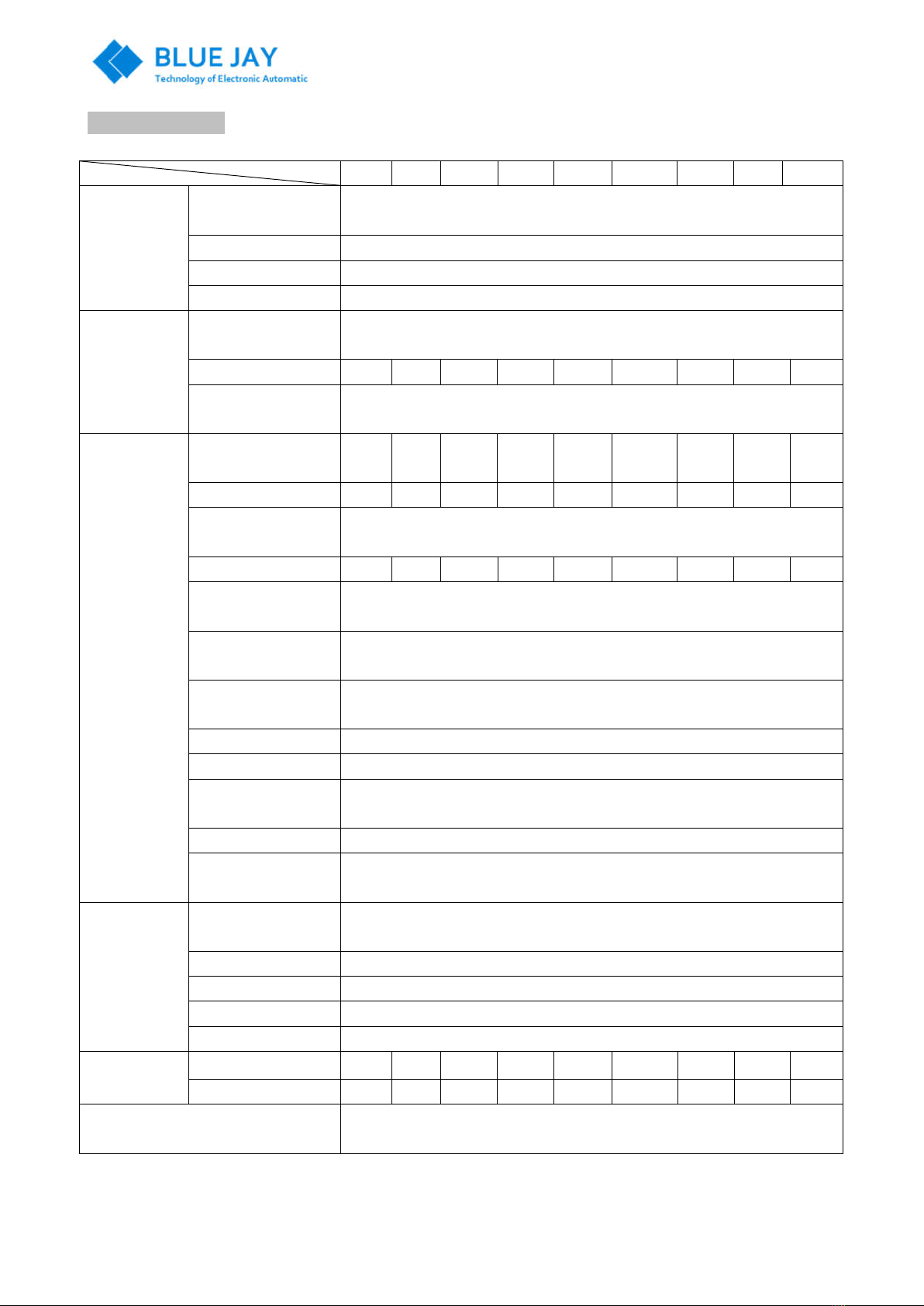
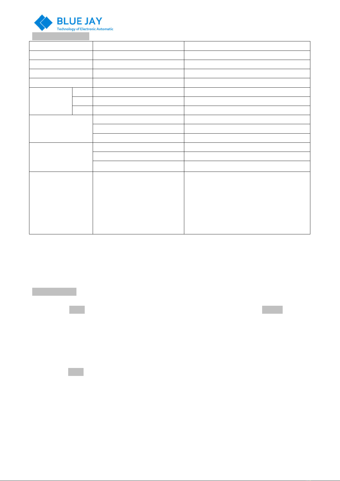
PART 3. Specification
Table 1
0.5K
1K 2K 3K 4K 5K 6K 8K 10K
DC Input
Rate input
Voltage/Vdc Table 2
Rate input Current/A Table 2
Input dc range Voltage
Table 2
Reverse noise Current
≤10%
AC Bypass
input
Allow bypass voltage
(Vac) 220Vac±20%
Rate input current/A 1.8A
3.6A
7.2A 10.8A
14.5A
18.2A 21.8A
29A 36A
Bypass conversion
time/ms ≤5ms
AC Output
Rated output
Capacity/KVA 0.5K
1K 2K 3K 4K 5K 6K 8K 10K
Rated output power/W
400 800
1600
2400
3200
4000 4800
6400
8000
Rated output voltage
and frequency 220Vac,50Hz
Rate output current/A
1.8 3.6 7.2 10.8 14.5 18.2 21.8 29 36.3
Output voltage
accuracy/V 220±3%
Output frequency
accuracy/Hz 50±0.1%
Waveform distortion
rate (THD) ≤3%(Linear load)
Dynamic Response 5%(Load 25%←→100%)
Power Factor/PF 0.8
Over load ability ≥100%~125%,10mins; 125%~150%,15seconds; 150%, shut down
Immediately
Efficiency ≥85%(80% Resistive load)
Bypass conversion
time/ms ≤5ms
Operating
Environment
Insulation strength
(input and output) 1500Vac,1min
Noise/1m ≤40dB
Operating temperature
-25℃~+50℃
Humidity 0~90%,no cooling
Altitude /m ≤1000
Dimension Rack Mount AB AB AB C C C C D D
Weight/Kg 4.8/6
5/6 6/7 12 13 14 15 20 22
Protect function Input lower voltage, input overvoltage protection; output overload protection,
output short circuit protection
Note: The rated output power with error 500VA ± 50W; 1-10KVA is ± 100W
User Manual
Tel: +0086-023-67628702 Email:tech@cqbluejay.com
www.cqbluejay.com
Add: Block 3A-13-25, No.153 Jingyu Avenue, Jiangbei Qu, Chongqing City 401147
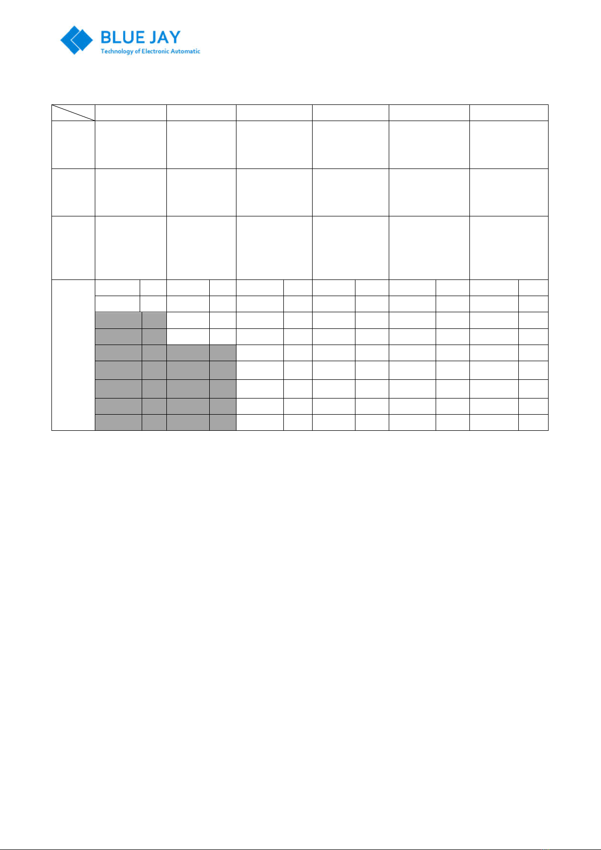
Table 2
Inverter input DC voltage (Vdc) (Error: +/-0.5~1V)
12V Series 24V Series 48V Series 110V Series 220V Series 240V Series
Rate
input
voltage
12Vdc 24Vdc 48Vdc 110Vdc 220Vdc 240Vdc
working
voltage
range
9.8V—14.5V 20V—30.5V 40V—58.8V 90V—145V 180V—270V 200V—300V
Start up
/Boot
voltage
range
10.2V--14.2V 21.5V—29.5V
42V--57V 94V--142V 190V--265V 210V--295V
Rate
input
current
500VA 40A
500VA
20A
500VA 9.8A
500VA
4.3A
500VA 2.2A
500VA 1.9A
1KVA 76A
1KVA 38A
1KVA 19A
1KVA 8.3A
1KVA 4.2A
1KVA 3.9A
2 KVA 76
2 KVA 38 2 KVA 16.6
2 KVA 8.3 2 KVA 7.8
3 KVA 117
3 KVA 57 3 KVA 24.9
3 KVA 12.4
3 KVA 11.7
4 KVA 77 4 KVA 33.4
4 KVA 16.7
4 KVA 15.6
5 KVA 98 5 KVA 36.6
5 KVA 18.3
5 KVA 19.6
6 KVA 117
6 KVA 51.3
6 KVA 22 6 KVA 23.5
8 KVA 156
8 KVA 68 8 KVA 34.2
8 KVA 34.2
10 KVA
196
10 KVA
85 10 KVA
42.7
10 KVA 39
Remarks:
1. Due to the difference in the instrument used during the test, the range points may be slightly deviated.
2. The input current size determines the input switch size configuration
Explanation:
1. In order to protect the battery, the inverter can start normally only when the battery voltage is within the START UP/Boot
voltage range.
2. After the inverter switched on and inverter can work normally within the working voltage range work under the battery or
DC power supply mode. When the battery or DC voltage drops to the lower working voltage limit, the inverter will be
power off.
User Manual
Tel: +0086-023-67628702 Email:tech@cqbluejay.com
www.cqbluejay.com
Add: Block 3A-13-25, No.153 Jingyu Avenue, Jiangbei Qu, Chongqing City 401147
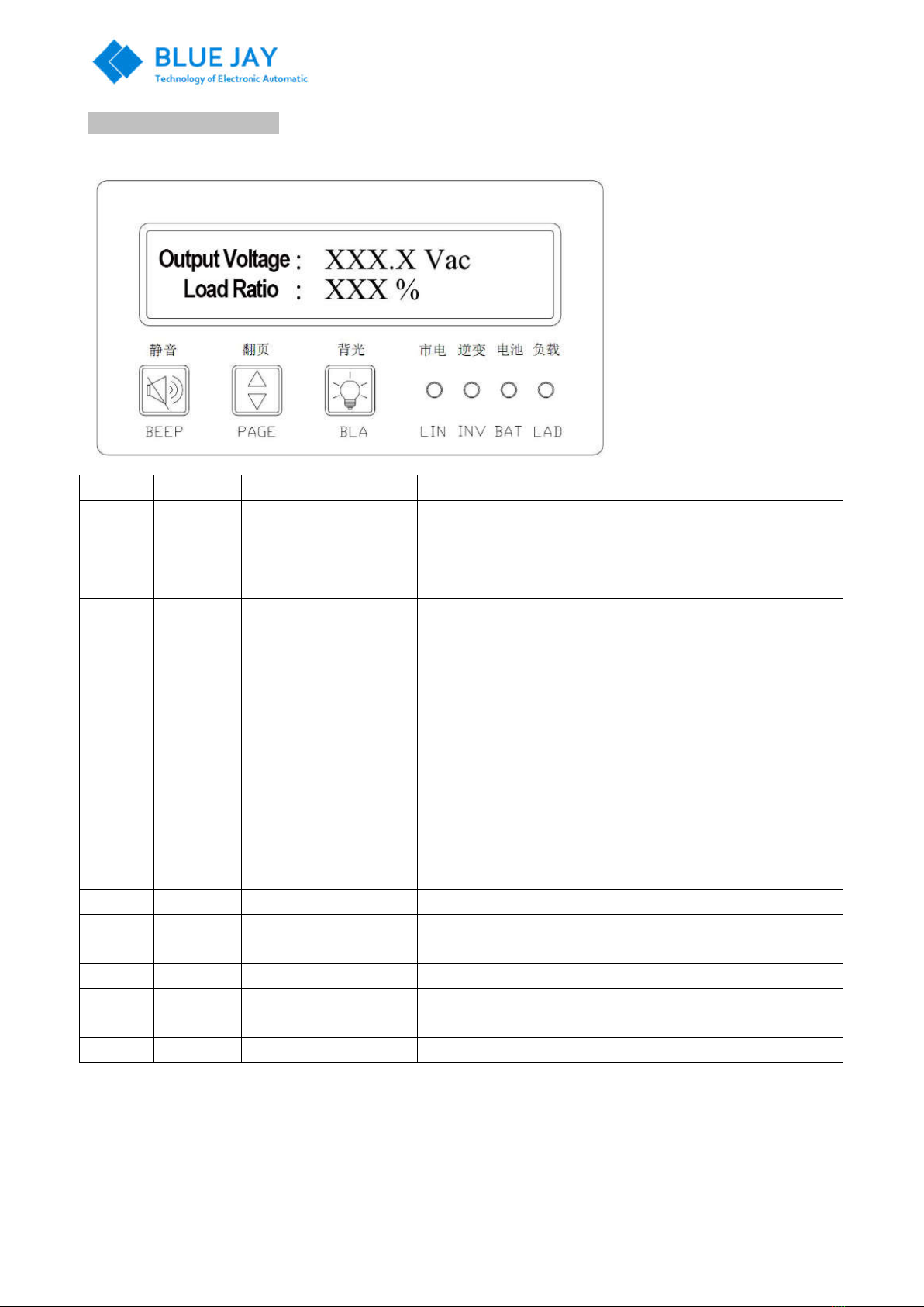
PART 4. Front panel introduce
LED indicator
Item Panel Full name Definition
1 BEEP BEEP button
1. When the buzzer sounds, press and hold for 1~2 seconds to
turn off the buzzer
2. When the alarm is on and the buzzer is off, press BEEP Button
for 1-2 seconds to turn on the buzzer
2 PAGE Page button
1. For LCD screen up and down
2. There are three pages on the LCD screen and each page
shows two lines of content
First page:
Output voltage: XXX.X Vac
Load ratio: XXX %
Second page:
DC input: XXX.X Vdc
AC input: XXX.X Vac
Third page:
Load power: XX.XX kW
Output frequency: XX.X Hz
3 BLA Backlight button Press the backlight key(BLA), the backlight is on
4 LIN AC City Power indicator The LIN Indicator ON Mean the inverter work in AC input and ac
output in bypass mode
5 INV Invert indicator The INV Indicator ON Means the inverter work in DC input
6 BAT Battery indicator The BAT Indicator ON When the battery or DC input voltage is out
the working range of the inverter
7 LAD Load indicator The LAD Indicator ON when the inverter fail to work

User Manual
Tel: +0086-023-67628702 Email:tech@cqbluejay.com
www.cqbluejay.com
Add: Block 3A-13-25, No.153 Jingyu Avenue, Jiangbei Qu, Chongqing City 401147
PART 5. Diagram of inverter
PART 6. Working Principle of Inverter
AC Mains bypass mode
In the AC mains bypass mode, the mains power is switched to the output via a relay, and the mains bypass directly
supplies power. When the main fails, it automatically switches to the inverter and is powered by the battery or DC to
ensure uninterrupted power supply to the equipment.
inverter mode
In the inverter mode, after the DC boost inverter is reversed, it is switched to the output via a relay and directly powered
by the battery or DC. When the inverter fails, it automatically switches to the bypass and is powered by the mains to
ensure the uninterrupted power supply of the equipment.
PART 7. Installation and operation
Check if the package is damaged
Due to possible damage to the machine during transportation, please check the packing of the goods when receiving the
goods that the goods company is carrying. In case of any damage, please indicate on the receipt.
Storage
Keep it in a cool, dry, ventilated place away from highly corrosive, dusty, hot, and humid environments. If you do not use
the inverter for a long period of time, you should be able to use it every 6months
Check the machine nameplate:
Check if the specification, type, output capacity, input AC voltage, input DC voltage, output AC voltage, etc., meet the
contents specified at the time of ordering. Check the machine for damage during transportation.
Confirming Installation Conditions
1. No dust, choose a ventilated, clean installation environment;
2. The proper ambient temperature
3. Relative humidity meets requirements
4. No corrosive gas such as steam
5. No flammable and explosive products nearby
6. There is a power supply that complies with safety regulations
Connection leads
1. Make sure all switches are off.
2. Connect the host's DC input cable correctly. Note the positive and negative polarity.
3. Connect the host AC input cable correctly.
4. Connect the host AC output cable correctly.
5. Connect the host to a good ground wire.

User Manual
Tel: +0086-023-67628702 Email:tech@cqbluejay.com
www.cqbluejay.com
Add: Block 3A-13-25, No.153 Jingyu Avenue, Jiangbei Qu, Chongqing City 401147
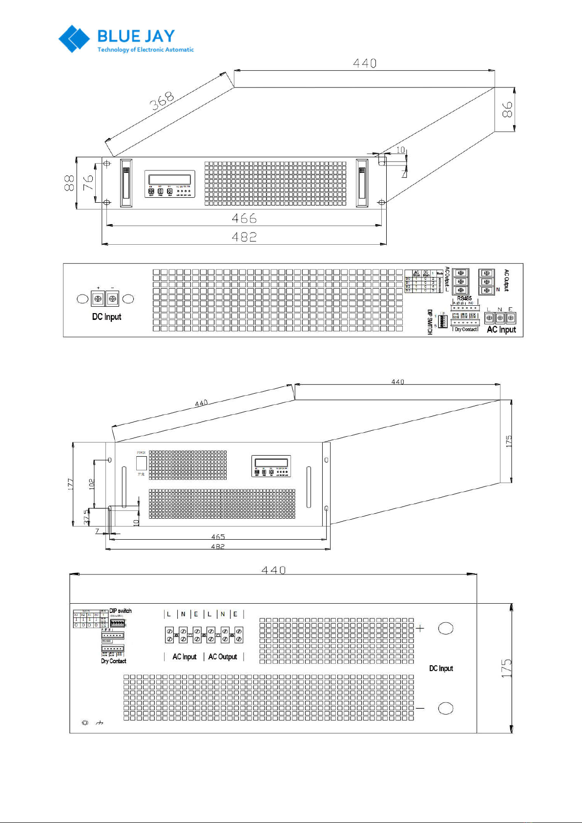
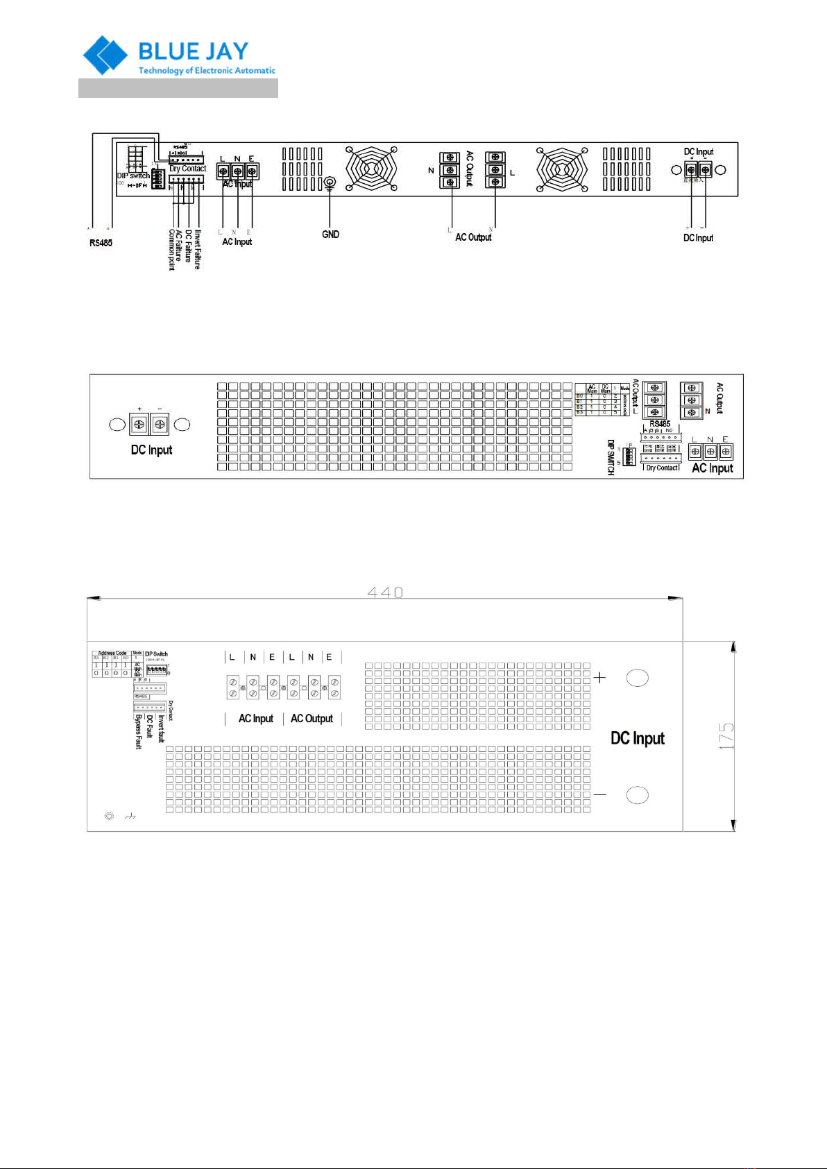
PART 8.Appearance & Dimension
19inch 1U Rack Mount Front & Rear View
500VA -2000VA Front & Rear View
User Manual
Tel: +0086-023-67628702 Email:tech@cqbluejay.com
www.cqbluejay.com
Add: Block 3A-13-25, No.153 Jingyu Avenue, Jiangbei Qu, Chongqing City 401147
3KVA-6KVA Front & Rear View
8KVA-10KVA Front & Rear View
User Manual
Tel: +0086-023-67628702 Email:tech@cqbluejay.com
www.cqbluejay.com
Add: Block 3A-13-25, No.153 Jingyu Avenue, Jiangbei Qu, Chongqing City 401147
PART 9.Wiring diagram description
1U Rack Mount type
2U Rack Mount type
4U Rack Mount type
User Manual
Tel: +0086-023-67628702 Email:tech@cqbluejay.com
www.cqbluejay.com
Add: Block 3A-13-25, No.153 Jingyu Avenue, Jiangbei Qu, Chongqing City 401147
PART 10.Wiring diagram
Port name Functional description Remark
DC Input + Battery Input + DC Module Input “+” Terminal
DC Input - Battery Input - DC Module Input “-” Terminal
AC Output L AC Output L Output Line Wire
AC Output N AC Output N Output Neutral Wire
AC Input
L AC Input L Input Line Wire
N AC Input N Input Neutral Wire
E Earth Earth Wire
Dry contact
City electricity fault Two points are connected when it is failure
DC Fault Two points are connected when it is failure
Invert Fault Two points are connected when it is failure
Communication port
A RS485A
B RS485B
G GND
DIP Switch
Mode selection
“1” mean AC for main input
“0” mean DC for main input
BO-B3(2-5)address code range from
00~15,The lowest address code is 0
and highest address code is 15
It can set 15pcs address code
After the operation of the dialing switch
It should be reboot the inverter after switch “DIP
switch” , if not , it did not work
Switch the DIP switch to the digital side is 1
Switch the DIP switch to the NO side is 0
(0000-1111)
Noted
Connect the inverter with the Earth is necessary to make sure it can safety and normal operation of the inverter and
reduce electromagnetic interference.
The grounding wire must be grounded (GND) and the earth grounding terminal should be as close to the instrument as
possible.
PART 11.Operating
1. Switch on of the inverter (Recommend turn on the inverter switch first then switch the load )
2. Press the "switch" button, the inverter will have 1-5seconds of "BEEP" mean the inverter under Self Test and it has
been started-up.
3. All Inverter start up with Self Test function , as before the inverter with stabilized output, it should be check whether the
external environment and the inverter are normal. If the inverter and all status parameters of the utility power are normal,
the inverter power supply will work stably in the utility power or inverter state. This process needs approximately 10
seconds
4. Switch off (Recommend turn on the Load switch first then switch the Inverter)
5. Press the "switch" button and turn off the inverter.
User Manual
Tel: +0086-023-67628702 Email:tech@cqbluejay.com
www.cqbluejay.com
Add: Block 3A-13-25, No.153 Jingyu Avenue, Jiangbei Qu, Chongqing City 401147
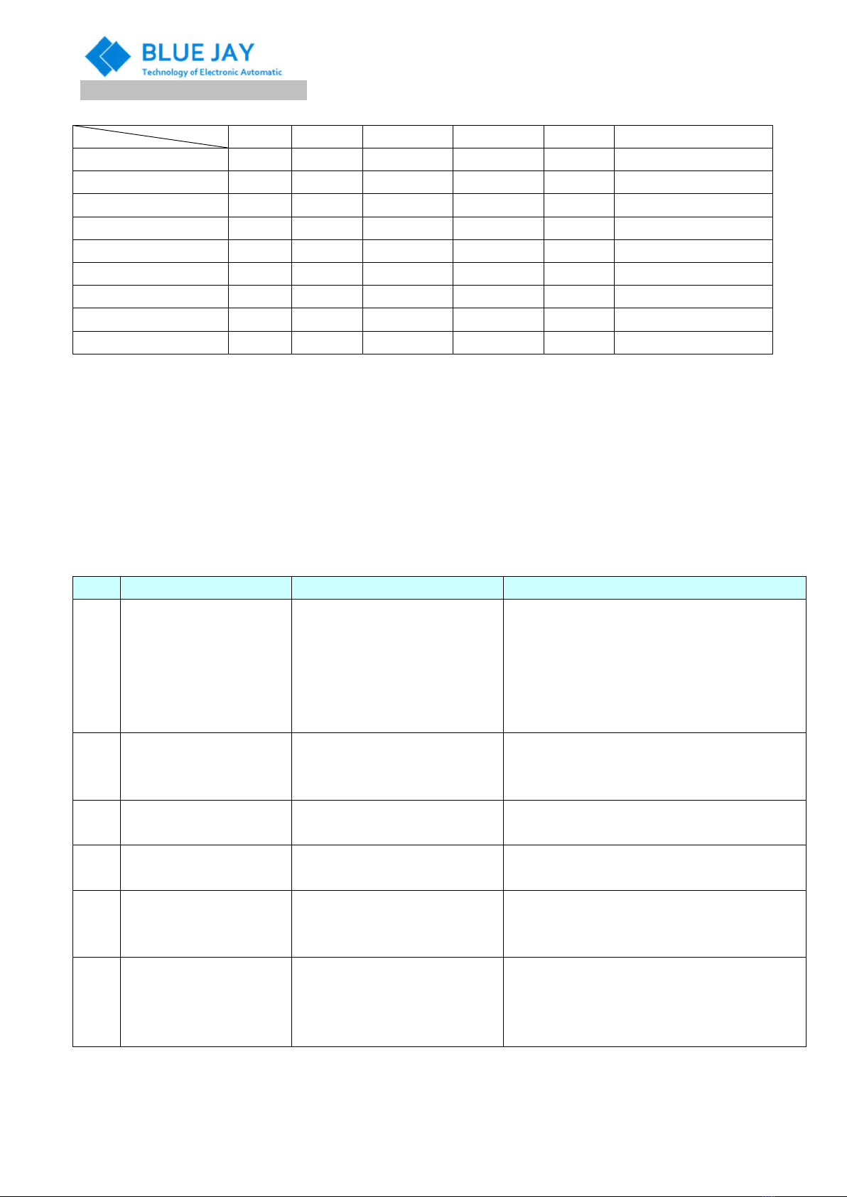
PART 12.Common Fault Analysis Table
LED and buzzer combination status table
LIN INV BAT Load TEMP Beep
AC Mains output ON OFF
Inverter output OFF ON
DC overvoltage 1s 1flash 1s 1 buzzer
DC lower voltage 3s 1flash 3s 1 buzzer
Overload 150% ON Without stopping buzzer
Overload 125~150% 1s 1flash 1s 1 buzzer
Overload 100~125% 3s 1flash 3s 1 buzzer
Over temperature 1s 1flash 1s 1flash 1s 1flash
1s 1 buzzer
Inverter failure ON ON ON Without stopping buzzer
Remark
1. Blank form indicates mean that it should be refer to related items
2. For example: "LINE" is ON, "INV" is OFF, "BAT" flashes for 1 second, "Load" goes off, and buzzer sounds for 1 second. IT
means In the ac output state, DC input over voltage, normal load, no over temperature
Fault Analysis Table
1. When the inverter fails, the red signal indicator on the front panel will be “ON”
2. According to different fault conditions appear as long and alarm or flashing.
3. You can determine the cause of the fault by looking at the indicators on the front panel and refer to the following
figure for proper handling.
Item
Fault Possible Reason Solutions
1 Battery, load, over
temperature LED, 1s 1 flash
Turn off the output due to internal
overheating
1. Check the fan is running or not
2. Check the air vents are blocked or not
3. The environment temperature is too high or not
4. Reduce the load
5. Wait 10 minutes for inverter cooling and drop of
the temperature then restart
2 The load LED Indicator ON
and the buzzer sounds
1. Overload more than 150%
2. Internal failure to shut down
the inverter
1. Check whether running in overload
2. If yes, Reduce the load and restart
3 Battery LED Indicator ON.
3s1 flash, buzzer 3s 1 sound
Input DC voltage is too lower Check the DC input voltage is too lower and out of
the range for the inverter requirements
4 Battery LED Indicator ON.
1s1 flash, buzzer 1s 1 sound
Input DC voltage is too higher Check the DC input voltage is too higher and out of
the range for the inverter requirements
5
Load LED Indicator, 3
seconds 1 flash, buzzer 3
seconds 1 sound
Overload 100~125% 1. Check whether running in overload
2. If yes, Reduce the load and restart
6
The LINE Indicator OFF
after connect with AC City
main Power
AC Mains voltage and frequency
exceed the input limited range
1. Check if the AC mains voltage and frequency
exceed the inverter input range.
2. Check whether the power switch on the panel is
switch on or not .

User Manual
Tel: +0086-023-67628702 Email:tech@cqbluejay.com
www.cqbluejay.com
Add: Block 3A-13-25, No.153 Jingyu Avenue, Jiangbei Qu, Chongqing City 401147
7
Connect DC Power source
for input, turn on the power
switch and the machine
does not respond
1. The input DC voltage does not
meet the requirements or is
too lower
2. The input polarity is reversed.
1. Check if the DC input voltage is too lower can
not meets the requirements
2. Check if input polarity is reversed.
8
Customer's DC input circuit
breaker can not be switch
and close
1. Select the bigger capacity
circuit breaker
2. Inverter internal circuit failure
causes the machine to short
circuit
1. Select the bigger capacity circuit breaker
2. Switch on the DC circuit breaker then Switch
on the AC circuit breaker
3. If it still did not work mean the inverter internal
circuit are broken or short circuit
9 Can not switch the dc and
bypass in automatic
1. AC Mains voltage and
frequency exceed the Inverter
input limited range:
2. The dial switch (DIP Switch)on
the rear panel is set to the
wrong position.
1. Check whether the ac mains voltage and
frequency exceed the input range of the
inverter
2. Check whether the dial switch (DIP Switch) in
the corresponding position or not
10 For other fault be happen , please contact with factory after sale service support team.
PART 13.Maintenance
1. In order to ensure continuous normal operation of the inverter, regular maintenance and maintenance are required.
2. The installation and storage of inverter should avoid high corrosive, high dust, high temperature and high humidity
environments as much as possible.
3. Avoid metal material falling into the box.
4. Periodically check whether the connection line is aging and the cable connection point is tight and safe or not .
5. Clean the cooling fan regularly and check if the fan is normal.
This manual suits for next models
6
Popular Inverter manuals by other brands


Delta
Delta M70A-260 Installation and operation manual

CanadianSolar
CanadianSolar CSI-20KTL-GI-FL Installation and operation

Data Video
Data Video TC-200 quick start guide

Delta
Delta H5A 222 Series Quick installation guide

Alfain
Alfain PEGAS 160 T PULSE HF Service manual

Alfain
Alfain PEGAS 200 T PULSE HF operating manual

Delta
Delta M42U Operation and installation manual

Tripp Lite
Tripp Lite PowerVerter PVINT375 Specification sheet

Tripp Lite
Tripp Lite PowerVerter 200510095 owner's manual

Delta
Delta H8E Operation and installation manual

CanadianSolar
CanadianSolar CSI-3K-S22002-E user manual

FRONIUS
FRONIUS AquiSuite install guide